EP0441818B1 - A modular unit for releasable connection to the structure of a motor vehicle - Google Patents
A modular unit for releasable connection to the structure of a motor vehicle Download PDFInfo
- Publication number
- EP0441818B1 EP0441818B1 EP89911991A EP89911991A EP0441818B1 EP 0441818 B1 EP0441818 B1 EP 0441818B1 EP 89911991 A EP89911991 A EP 89911991A EP 89911991 A EP89911991 A EP 89911991A EP 0441818 B1 EP0441818 B1 EP 0441818B1
- Authority
- EP
- European Patent Office
- Prior art keywords
- rack
- bracket
- type
- subframe
- component
- Prior art date
- Legal status (The legal status is an assumption and is not a legal conclusion. Google has not performed a legal analysis and makes no representation as to the accuracy of the status listed.)
- Expired - Lifetime
Links
Images
Classifications
-
- B—PERFORMING OPERATIONS; TRANSPORTING
- B60—VEHICLES IN GENERAL
- B60G—VEHICLE SUSPENSION ARRANGEMENTS
- B60G21/00—Interconnection systems for two or more resiliently-suspended wheels, e.g. for stabilising a vehicle body with respect to acceleration, deceleration or centrifugal forces
- B60G21/02—Interconnection systems for two or more resiliently-suspended wheels, e.g. for stabilising a vehicle body with respect to acceleration, deceleration or centrifugal forces permanently interconnected
- B60G21/04—Interconnection systems for two or more resiliently-suspended wheels, e.g. for stabilising a vehicle body with respect to acceleration, deceleration or centrifugal forces permanently interconnected mechanically
- B60G21/05—Interconnection systems for two or more resiliently-suspended wheels, e.g. for stabilising a vehicle body with respect to acceleration, deceleration or centrifugal forces permanently interconnected mechanically between wheels on the same axle but on different sides of the vehicle, i.e. the left and right wheel suspensions being interconnected
- B60G21/055—Stabiliser bars
- B60G21/0551—Mounting means therefor
-
- B—PERFORMING OPERATIONS; TRANSPORTING
- B60—VEHICLES IN GENERAL
- B60G—VEHICLE SUSPENSION ARRANGEMENTS
- B60G7/00—Pivoted suspension arms; Accessories thereof
- B60G7/02—Attaching arms to sprung part of vehicle
-
- B—PERFORMING OPERATIONS; TRANSPORTING
- B60—VEHICLES IN GENERAL
- B60G—VEHICLE SUSPENSION ARRANGEMENTS
- B60G99/00—Subject matter not provided for in other groups of this subclass
-
- B—PERFORMING OPERATIONS; TRANSPORTING
- B62—LAND VEHICLES FOR TRAVELLING OTHERWISE THAN ON RAILS
- B62D—MOTOR VEHICLES; TRAILERS
- B62D21/00—Understructures, i.e. chassis frame on which a vehicle body may be mounted
- B62D21/11—Understructures, i.e. chassis frame on which a vehicle body may be mounted with resilient means for suspension, e.g. of wheels or engine; sub-frames for mounting engine or suspensions
-
- B—PERFORMING OPERATIONS; TRANSPORTING
- B62—LAND VEHICLES FOR TRAVELLING OTHERWISE THAN ON RAILS
- B62D—MOTOR VEHICLES; TRAILERS
- B62D3/00—Steering gears
- B62D3/02—Steering gears mechanical
- B62D3/12—Steering gears mechanical of rack-and-pinion type
-
- B—PERFORMING OPERATIONS; TRANSPORTING
- B60—VEHICLES IN GENERAL
- B60G—VEHICLE SUSPENSION ARRANGEMENTS
- B60G2200/00—Indexing codes relating to suspension types
- B60G2200/10—Independent suspensions
-
- B—PERFORMING OPERATIONS; TRANSPORTING
- B60—VEHICLES IN GENERAL
- B60G—VEHICLE SUSPENSION ARRANGEMENTS
- B60G2200/00—Indexing codes relating to suspension types
- B60G2200/10—Independent suspensions
- B60G2200/14—Independent suspensions with lateral arms
- B60G2200/154—Independent suspensions with lateral arms the lateral arm having an L-shape
-
- B—PERFORMING OPERATIONS; TRANSPORTING
- B60—VEHICLES IN GENERAL
- B60G—VEHICLE SUSPENSION ARRANGEMENTS
- B60G2204/00—Indexing codes related to suspensions per se or to auxiliary parts
- B60G2204/10—Mounting of suspension elements
- B60G2204/12—Mounting of springs or dampers
- B60G2204/122—Mounting of torsion springs
- B60G2204/1222—Middle mounts of stabiliser on vehicle body or chassis
-
- B—PERFORMING OPERATIONS; TRANSPORTING
- B60—VEHICLES IN GENERAL
- B60G—VEHICLE SUSPENSION ARRANGEMENTS
- B60G2204/00—Indexing codes related to suspensions per se or to auxiliary parts
- B60G2204/10—Mounting of suspension elements
- B60G2204/14—Mounting of suspension arms
- B60G2204/143—Mounting of suspension arms on the vehicle body or chassis
- B60G2204/1431—Mounting of suspension arms on the vehicle body or chassis of an L-shaped arm
-
- B—PERFORMING OPERATIONS; TRANSPORTING
- B60—VEHICLES IN GENERAL
- B60G—VEHICLE SUSPENSION ARRANGEMENTS
- B60G2204/00—Indexing codes related to suspensions per se or to auxiliary parts
- B60G2204/10—Mounting of suspension elements
- B60G2204/15—Mounting of subframes
-
- B—PERFORMING OPERATIONS; TRANSPORTING
- B60—VEHICLES IN GENERAL
- B60G—VEHICLE SUSPENSION ARRANGEMENTS
- B60G2206/00—Indexing codes related to the manufacturing of suspensions: constructional features, the materials used, procedures or tools
- B60G2206/01—Constructional features of suspension elements, e.g. arms, dampers, springs
- B60G2206/012—Hollow or tubular elements
-
- B—PERFORMING OPERATIONS; TRANSPORTING
- B60—VEHICLES IN GENERAL
- B60G—VEHICLE SUSPENSION ARRANGEMENTS
- B60G2206/00—Indexing codes related to the manufacturing of suspensions: constructional features, the materials used, procedures or tools
- B60G2206/01—Constructional features of suspension elements, e.g. arms, dampers, springs
- B60G2206/60—Subframe construction
Definitions
- the invention relates to a detachably attachable to the vehicle body of a motor vehicle, which in itself has the functions of a u. a. the pivotable articulation of - preferably triangular - wheel guide arms serving subframes (subframe) and a housing of a rack and pinion steering with upper and / or lower belt-shaped stiffeners extending along the housing, as is known for example from FR-A-2 295 850.
- subframes and subframes are increasingly being used because, among other things, they allow greater structural freedom with regard to the articulation of the wheel-guiding wheel control handlebars, open up possibilities for noise insulation in the passenger compartment and also offer possibilities for increasing the degree of automation in the final assembly of the vehicle.
- Such subframes require a high degree of lateral stiffness with regard to the support of the driving forces introduced by the vehicle wheels, a deliberately soft connection to the longitudinal members of the vehicle chassis with regard to a possible head-on collision and, in addition, the greatest possible bending stiffness, especially if the Subframe is also used for support or for partial support of units (engine, transmission, differential).
- subframes or subframes are manufactured as single or double-sheet metal frames from deep-drawn sheets.
- multi-part bearing brackets are screwed to the two ends of the box-shaped steering housing equipped with belt-shaped stiffeners, each of which on the one hand forms a bearing block for pivotable articulation of the wheel control arm and on the other hand each has an upper plate-shaped bracket area for screwing onto the vehicle body.
- the object of the invention is to create a subframe construction or structural unit of the type mentioned in the preamble of patent claim 1 which is improved in comparison to the prior art and which saves space and weight and is nevertheless sufficiently rigid.
- the light metal cast housing of a motor vehicle rack and pinion steering is used as the basis for the subframe by providing the actual rack and pinion cast housing with suitable rib, web and / or belt-like longitudinal and transverse stiffeners and with console-like side sprues, some of which are equipped serve to fasten the resulting one-piece rack-and-pinion subframe assembly made of light metal casting on the vehicle body and otherwise serve for pivotable articulation of preferably triangular transverse or diagonal links on this assembly.
- the subframe / rack casting housing assembly according to the invention is characterized by rigidity, comparatively low weight and comparatively small space requirement and has the essential advantage that it can be adapted to the given, sometimes very complicated space conditions comparatively easily.
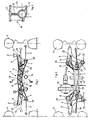
- the wheels 4 of the vehicle which can be steered via tie rods 16 of a rack and pinion steering system, are each pivotably articulated via a lower triangular wishbone 3 to an auxiliary frame, which in turn is detachably screwed to the vehicle body 2, which is only indicated.
- Other necessary wheel guide members be it an upper wishbone or a wheel-guiding suspension strut, and the wheel carrier (steering knuckle) itself are not shown because of the better overview.
- the auxiliary frame and the rack-and-pinion steering or the housing 5 of the rack-and-pinion steering are formed into an integrated, one-piece structural unit 1 made of light metal casting, preferably made of die-cast aluminum or magnesium.
- the light metal cast housing is provided with rib-like, web-like and / or belt-like stiffeners 10 - 13 cast on along its circumference and its length, and with lateral console-like sprues 7 to 9 provided, in the lateral console-like sprues on the one hand bearings 22 for releasably attaching this unit to the vehicle body 2 and on the other hand bearings 20, 21 are provided for pivotably articulating the control arm 3 on the unit;
- the one bearing 20 is designed in a known manner so that it serves both for fastening the assembly to the vehicle body 2 and for the articulation of the control arm 3.
- the housing part 5 which receives the rack 23 and is oriented transversely to the longitudinal direction of the vehicle and which represents the actual rack-and-pinion steering housing and in the usual way has an essentially circular cross-section
- two in plan view approximately Y-shaped obliquely outwards Diverging console-like sprues 7, 8 are formed with bearings 20, 21 arranged at their ends, which primarily serve to pivot the control arm 3 and, in the exemplary embodiment, lie approximately in the same horizontal plane, but this depends in individual cases on the desired kinematics of the wheel guide.
- one of the two bearings, namely bearing 20, also serves at the same time for fastening the cast assembly to the vehicle body 2.
- a further lateral bracket-like sprue 9 is provided above the level that is fictitiously defined by the first two bracket-like sprues 7, 8. At its end, this carries a bearing 22, which is used for releasably fastening the structural unit to the vehicle body 2.
- a T-beam-shaped stiffening 10 extending longitudinally above the housing part 5 receiving the rack 23 is approximately horizontal top flange 11 and approximately vertical Web 12 (Fig. 3) is provided, which opens into the laterally spread console-like sprues 7, 8 and whose vertical web 12 runs approximately symmetrically into the circular cross-section of the housing part 5, at least in the central region.
- On both sides of the stiffening 10 there are alternately oppositely inclined transverse ribs 13 which each extend from the upper chord 11 to the lower region of the housing part 5, in the exemplary embodiment shown up to a corresponding lower chord 17.
- stiffeners e.g. B. U-shaped stiffeners or the like can be used analogously.
- the stiffening 10 - seen in the longitudinal direction of the vehicle - is arched like a bridge, d. H. so that it runs from a central arch apex to the laterally spread console-like sprues 7, 8 sloping downwards and ends there in the console-like sprues 7, 8.
- This bridge-like curvature is advantageous if on the assembly 1 also aggregate parts, for. B. a differential 18 must be supported, and it also facilitates, for. B. to pass the pipe 14 of an exhaust system or the shift linkage 15 of a change gear under the unit 1.
Abstract
Description
Die Erfindung betrifft eine am Fahrzeugaufbau eines Kraftfahrzeugs lösbar befestigbare Baueinheit, die in sich die Funktionen eines u. a. der schwenkbaren Anlenkung von - vorzugsweise dreieckförmigen - Radführungslenkern dienenden Hilfsrahmens (Fahrschemels) sowie eines Gehäuses einer Zahnstangenlenkung mit sich längs des Gehäuses erstreckenden oberere und/oder unteren gurtförmigen Versteifungen vereinigt, wie sie beispielsweise aus der FR-A-2 295 850 bekannt ist.The invention relates to a detachably attachable to the vehicle body of a motor vehicle, which in itself has the functions of a u. a. the pivotable articulation of - preferably triangular - wheel guide arms serving subframes (subframe) and a housing of a rack and pinion steering with upper and / or lower belt-shaped stiffeners extending along the housing, as is known for example from FR-A-2 295 850.
Im modernen Personenkraftwagenbau werden Hilfsrahmen bzw. Fahrschemel zunehmend eingesetzt, weil sie u. a. größere konstruktive Freizügigkeit bezüglich der aufbauseitigen Anlenkung der radführenden Radführungslenker ermöglichen, verbesserte Möglichkeiten zur Geräuschisolierung des Fahrgast-Innenraums eröffnen und darüber hinaus Möglichkeiten zur Vergrößerung des Automatisierungsgrades bei der Endmontage des Fahrzeuges bieten.In modern passenger car construction, subframes and subframes are increasingly being used because, among other things, they allow greater structural freedom with regard to the articulation of the wheel-guiding wheel control handlebars, open up possibilities for noise insulation in the passenger compartment and also offer possibilities for increasing the degree of automation in the final assembly of the vehicle.
Von solchen Hilfsrahmen wird im Hinblick auf die Abstützung der von den Fahrzeugrädern eingeleiteten Fahrkräfte eine hohe Quersteifigkeit, im Hinblick auf einen eventuellen Frontalzusammenstoß eine gezielt weiche Anbindung an den Längsträgern des Fahrzeug-Chassis und darüber hinaus eine möglichst hohe Biegesteifigkeit verlangt, insbesondere dann, wenn der Hilfsrahmen zusätzlich auch zur Abstützung oder aber zur Teilabstützung von Aggregaten (Motor; Getriebe, Differential) herangezogen wird.Such subframes require a high degree of lateral stiffness with regard to the support of the driving forces introduced by the vehicle wheels, a deliberately soft connection to the longitudinal members of the vehicle chassis with regard to a possible head-on collision and, in addition, the greatest possible bending stiffness, especially if the Subframe is also used for support or for partial support of units (engine, transmission, differential).
Im modernen Personenkraftwagenbau wird unter äußerster Nutzung des vorhandenen Bauraums eine möglichst kompakte Bauweise angestrebt, was häufig zu vergleichsweise komplizierten Bauformen u. a. auch des Hilfsrahmens führt, weil auf benachbarte andere Bauteile Rücksicht genommen werden muß. Verstärkt treten solche Probleme bei Fahrzeugen der Unterklasse und der unteren Mittelklasse auf.In modern passenger car construction, the most compact possible construction is aimed at using the available space, which often leads to comparatively complicated designs and. a. also leads to the subframe, because neighboring other components must be taken into account. Such problems occur increasingly in vehicles of the lower and lower middle class.
Üblicherweise werden die Hilfsrahmen bzw. Fahrschemel als ein- oder zweischalige Blechrahmen aus Tiefziehblechen hergestellt. Bei komplizierter gestalteten Hilfsrahmen ergeben sich somit häufig Fertigungsschwierigkeiten aufgrund großer Ziehtiefen o. ä. sowie Steifigkeits- und Gewichtsprobleme.Usually, the subframes or subframes are manufactured as single or double-sheet metal frames from deep-drawn sheets. In the case of more complicated subframes, there are often manufacturing difficulties due to large drawing depths or the like, as well as rigidity and weight problems.
Aus der FR-A-2 295 850 ist nun bereits eine vergleichsweise kompakte Hilfsrahmenkonstruktion bekannt, in welcher die Funktionen des Gehäuses einer- Zahnstangenlenkung sowie die eines Fahrschemels, an dem ein dreieckförmiger Radführungslenker mit einem seiner beiden Lenkerlager angelenkt ist, vereinigt sind.From FR-A-2 295 850 a comparatively compact subframe construction is already known, in which the functions of the housing of a rack and pinion steering and that of a subframe, to which a triangular wheel control arm is articulated with one of its two link bearings, are combined.
Bei dieser bekannten Baueinheit sind an den beiden Enden des mit gurtförmigen Versteifungen ausgestatteten kastenförmigen Lenkungsgehäuses mehrteilige Lagerkonsolen angeschraubt, die jeweils einerseits einen Lagerbock zur schwenkbaren Anlenkung der Radführungslenker bilden und andererseits jeweils einen oberen plattenförmigen Konsolenbereich zum Anschrauben am Fahrzeugaufbau aufweisen.In this known assembly, multi-part bearing brackets are screwed to the two ends of the box-shaped steering housing equipped with belt-shaped stiffeners, each of which on the one hand forms a bearing block for pivotable articulation of the wheel control arm and on the other hand each has an upper plate-shaped bracket area for screwing onto the vehicle body.
Vor diesem Hintergrund liegt der Erfindung die Aufgabe zugrunde, eine im Vergleich zum Stand der Technik verbesserte raum- und gewichtssparende und trotzdem ausreichend steife Hilfsrahmenkonstruktion bzw. Baueinheit der im Oberbegriff des Patentanspruchs 1 genannten Art zu schaffen.Against this background, the object of the invention is to create a subframe construction or structural unit of the type mentioned in the preamble of
Diese Aufgabe wird erfindungsgemäß durch die Merkmale des Patentanspruchs 1 gelöst.This object is achieved by the features of
Erfindungsgemäß wird also das Leichtmetall-Gußgehäuse einer Kfz-Zahnstangenlenkung als Grundlage für den Hilfsrahmen ausgenutzt, indem das eigentliche Zahnstangen-Gußgehäuse mit geeigneten rippen-, steg- und/oder gurtartigen Längs- und Querversteifungen versehen und mit konsolenartigen seitlichen Angüssen ausgestattet wird, die einenteils zur Befestigung der so entstandenen einstückigen Zahnstangenlenkungs-Hilfsrahmen-Baueinheit aus Leichtmetallguß am Fahrzeugaufbau und anderenteils zur schwenkbaren Anlenkung von vorzugsweise dreieckförmigen Quer- oder Schräglenkern an dieser Baueinheit dienen.According to the invention, the light metal cast housing of a motor vehicle rack and pinion steering is used as the basis for the subframe by providing the actual rack and pinion cast housing with suitable rib, web and / or belt-like longitudinal and transverse stiffeners and with console-like side sprues, some of which are equipped serve to fasten the resulting one-piece rack-and-pinion subframe assembly made of light metal casting on the vehicle body and otherwise serve for pivotable articulation of preferably triangular transverse or diagonal links on this assembly.
Vorteilhafte Ausgestaltungen und Weiterbildungen der Erfindung sind in den Unteransprüchen angegeben.Advantageous refinements and developments of the invention are specified in the subclaims.
Die erfindungsgemäße Hilfsrahmen/Zahnstangengußgehäuse-Baueinheit zeichnet sich durch Steifigkeit, vergleichsweise geringes Gewicht und vergleichsweise geringen Raumbedarf aus und besitzt den wesentlichen Vorteil, daß sie den gegebenen, mitunter sehr komplizierten Raumverhältnissen vergleichsweise einfach angepaßt werden kann.The subframe / rack casting housing assembly according to the invention is characterized by rigidity, comparatively low weight and comparatively small space requirement and has the essential advantage that it can be adapted to the given, sometimes very complicated space conditions comparatively easily.
Für Großserienfahrzeuge wird man anstreben, diese Guß-Baueinheit als Aluminium- oder Magnesium-Druckguß (bzw. Legierungen daraus) auszuführen. Es ist natürlich auch möglich, sie als Kokillenguß auszubilden oder im Wachsausschmelzverfahren herzustellenFor large-series vehicles, one will strive to use this cast unit as an aluminum or magnesium die-cast (or alloys thereof) to execute. It is of course also possible to design them as permanent mold casting or to use the lost wax process
Anhand eines in der Zeichnung dargestellten Ausführungsbeispieles wird die Erfindung nachstehend näher erläutert.Based on an embodiment shown in the drawing, the invention is explained in more detail below.
In der Zeichnung zeigen in prinzipienhafter Darstellung
- Fig. 1
- eine in Fahrzeuglängsrichtung gesehene Hilfsrahmen/Zahnstangenlenkungs-Baueinheit aus Leichtmetallguß,
- Fig. 2
- die entsprechende Baueinheit in einer Draufsicht und
- Fig. 3
- einen Querschnitt der Baueinheit entlang der Schnittführung III.
- Fig. 1
- a subframe / rack and pinion steering assembly made of light metal casting, seen in the longitudinal direction of the vehicle,
- Fig. 2
- the corresponding unit in a plan view and
- Fig. 3
- a cross section of the unit along the section III.
Die Zeichnung zeigt die Aufhängung lenkbarer Räder eines Kraftfahrzeuges, wobei nur die für das Verständnis der Erfindung notwendigen Einzelheiten der Radaufhängung dargestellt sind.The drawing shows the suspension of steerable wheels of a motor vehicle, only the details of the wheel suspension necessary for understanding the invention being shown.
Die über Spurstangen 16 einer Zahnstangenlenkung lenkbaren Räder 4 des Fahrzeuges sind jeweils über einen unteren dreieckförmigen Querlenker 3 schwenkbar an einem Hilfsrahmen angelenkt, der seinerseits lösbar am nur angedeuteten Fahrzeugaufbau 2 angeschraubt ist. Weitere notwendige Radführungsglieder, sei es ein oberer Querlenker oder ein radführendes Federbein, sowie der Radträger (Achsschenkel) selbst sind wegen der besseren Übersicht nicht weiter dargestellt.The
Der Hilfsrahmen und die Zahnstangenlenkung bzw. das Gehäuse 5 der Zahnstangenlenkung sind zu einer integrierten einstückigen Baueinheit 1 aus Leichtmetallguß ausgebildet, vorzugsweise aus Aluminium- oder Magnesium-Druckguß. Das Leichtmetall-Gußgehäuse ist zu diesem Zweck mit entlang seinem Umfang und seiner Länge angegossenen rippen-, steg- und/oder gurtartigen Versteifungen 10 - 13 sowie mit seitlichen konsolenartigen Angüssen 7 bis 9 versehen, wobei in den seitlichen konsolenartigen Angüssen einerseits Lager 22 zur lösbaren Befestigung dieser Baueinheit am Fahrzeugaufbau 2 und andererseits Lager 20, 21 zur verschwenkbaren Anlenkung des Querlenkers 3 an der Baueinheit vorgesehen sind; dabei ist das eine Lager 20 in bekannter Weise so ausgebildet, daß es gleichzeitig sowohl zur Befestigung der Baueinheit am Fahrzeugaufbau 2 als auch zur Anlenkung des Querlenkers 3 dient.The auxiliary frame and the rack-and-pinion steering or the
Im Ausführungsbeispiel sind an den beiden Enden des die Zahnstange 23 aufnehmenden, quer zur Fahrzeuglängsrichtung ausgerichteten Gehäuseteils 5, welches das eigentliche Zahnstangenlenkungs-Gehäuse darstellt und in üblicher Weise einen im wesentlichen kreisringförmigen Querschnitt besitzt, je zwei in der Draufsicht etwa Y-förmig schräg nach außen auseinanderlaufende konsolenartige Angüsse 7, 8 mit an ihren Enden angeordneten Lagern 20, 21 angeformt, welche primär der schwenkbaren Anlenkung des Querlenkers 3 dienen und im Ausführungsbeispiel etwa in der gleichen Horizontalebene liegen, was im Einzelfall jedoch von der angestrebten Kinematik der Radführung abhängt. Wie bereits zuvor erwähnt dient eins der beiden Lager, nämlich Lager 20 gleichzeitig auch zur Befestigung der Guß-Baueinheit am Fahrzeugaufbau 2. Je ein weiterer seitlicher konsolenartiger Anguß 9 ist oberhalb der fiktiv durch die beiden ersten konsolenartigen Angüsse 7, 8 gelegten Ebene vorgesehen. Dieser trägt endseitig ein Lager 22, welches zur lösbaren Befestigung der Baueinheit am Fahrzeugaufbau 2 dient.In the exemplary embodiment, at the two ends of the
In den Fällen, in denen in weit verbreiteter Weise nur eine der beiden Lagerstellen des dreieckförmigen Quer- bzw. Schräglenkers am Hilfsrahmen bzw. an der Baueinheit 1 angelenkt wird, die andere Lagerstelle des Radführungslenkers dagegen unmittelbar am Fahrzeugaufbau 2 angreift, kann an der integrierten Guß-Baueinheit 1 natürlich der entsprechende seitliche konsolenartige Anguß entfallen.In cases in which only one of the two bearing points of the triangular wishbone or semi-trailing arm is articulated on the subframe or on the
Im Ausführungsbeispiel ist eine oberhalb des die Zahnstange 23 aufnehmenden Gehäuseteils 5 längsverlaufende T-trägerförmige Versteifung 10 mit etwa horizontalem Obergurt 11 und etwa vertikalem Steg 12 (Fig. 3) vorgesehen, die in den seitlich abgespreizten konsolenartigen Angüssen 7, 8 einmündet und deren vertikaler Steg 12 zumindest im mittleren Bereich etwa symmetrisch in den kreisringförmigen Querschnitt des Gehäuseteils 5 einläuft. Beiderseits der Versteifung 10 sind abwechselnd gegenläufig schräggestellte Querrippen 13 angeordnet, die sich jeweils vom Obergurt 11 bis zum unteren Bereich des Gehäuseteils 5 erstrecken, im gezeigten Ausführungsbeispiel bis zu einem entsprechenden Untergurt 17. Es versteht sich, daß natürlich auch andere Versteifungen, z. B. U-trägerförmige Versteifungen o. ä. sinngemäß zur Anwendung kommen können.In the exemplary embodiment, a T-beam-
Im Mittelteil 6 der Baueinheit 1, d. h. im Bereich des die Zahnstange aufnehmenden Gehäuseteils 5 ist die Versteifung 10 - in Fahrzeuglängsrichtung gesehen - brückenartig gewölbt ausgebildet, d. h. so, daß sie von einem mittigen Bogenscheitelpunkt aus zu den seitlich abgespreizten konsolenartigen Angüssen 7, 8 hin leicht abfallend gebogen verläuft und dort in den konsolenartigen Angüssen 7, 8 endet. Diese brückenartige Wölbung ist von Vorteil, wenn auf der Baueinheit 1 auch Aggregateteile, z. B. ein Differential 18 abgestützt werden müssen, und erleichtert es darüber hinaus, z. B. das Rohr 14 einer Abgasanlage oder das Schaltgestänge 15 eines Wechselgetriebes unter der Baueinheit 1 hindurchzuführen.In the
Claims (5)
- A component (1) which is releasably attached to the vehicle bodywork (2) of a motor vehicle and which combines the functions of among other things the pivotable linkage of an auxiliary frame (subframe), which serves as wheel guiding transverse swinging arms (3) and is preferably triangular in shape, as well as of a housing of a rack and pinion steering having upper and/or lower flange-shaped reinforcing parts (11, 17) which extend longitudinally along the housing, characterised in that the component (1) is formed as a one-piece component cast in light metal, furthermore that in each case two bracket-type castings (7, 8) having bearings (20, 21) disposed at the end for the purpose of attaching the component (1) to the vehicle bodywork (2) and/or for articulating the pivotable wheel-guiding transverse swinging arms (3), are provided at both ends of a housing part (5) which accommodates the rack and pinion unit (23) and which has a substantially circular cross section and the castings (7, 8), when seen from above, diverge diagonally outwards approximately in a Y-shape and furthermore that in addition to the upper and/or lower flange-type reinforcing parts (11, 17) which extend longitudinally along the periphery of the housing part (5), further rib-shaped and cross-piece type reinforcing parts (10, 12, 13) are provided.
- A component according to claim 1, characterised by a further lateral bracket-type casting (9) which lies in each case above an imaginary plane lying through the two other bracket-type castings (7, 8) and comprises a bearing (22) for the purpose of attaching to the motor vehicle bodywork (2).
- A component according to claim 1 or 2, characterised by a reinforcing part (10) which comprises a T-shaped, U-shaped or double-T-bearer-shaped cross section and which extends along the housing part (5) accomodating the rack and pinion unit (23) and which terminates in the laterally outwardly diverging bracket-type castings (7, 8).
- A component according to claim 3, characterised by transverse ribs (13) which are disposed preferably on both sides of the reinforcing part (10) and which are arranged alternatively diagonally opposed.
- A component according to claim 3 or 4, characterised in that the reinforcing part (10) in the region of the housing part (5) accommodating the rack and pinion unit (23) extends, as seen from the longitudinal direction of the motor vehicle, slightly curved downwardly from a central top point of an arch towards the laterally outwardly diverging bracket-type castings (7, 8) and terminates in the bracket-type castings (7, 8).
Applications Claiming Priority (2)
| Application Number | Priority Date | Filing Date | Title |
|---|---|---|---|
| DE3837679 | 1988-11-05 | ||
| DE3837679 | 1988-11-05 |
Publications (2)
| Publication Number | Publication Date |
|---|---|
| EP0441818A1 EP0441818A1 (en) | 1991-08-21 |
| EP0441818B1 true EP0441818B1 (en) | 1993-08-11 |
Family
ID=6366621
Family Applications (1)
| Application Number | Title | Priority Date | Filing Date |
|---|---|---|---|
| EP89911991A Expired - Lifetime EP0441818B1 (en) | 1988-11-05 | 1989-10-20 | A modular unit for releasable connection to the structure of a motor vehicle |
Country Status (3)
| Country | Link |
|---|---|
| EP (1) | EP0441818B1 (en) |
| DE (1) | DE58905292D1 (en) |
| WO (1) | WO1990005083A1 (en) |
Cited By (3)
| Publication number | Priority date | Publication date | Assignee | Title |
|---|---|---|---|---|
| EP1510443A1 (en) * | 2003-08-25 | 2005-03-02 | Peugeot Citroen Automobiles S.A. | Motor vehicle with steering rack integrated in the front transversal beam |
| DE102006048946A1 (en) * | 2006-10-17 | 2008-04-24 | Volkswagen Ag | Subframe arrangement for motor vehicle, has transverse cross bar provided with vertical bar section extending upto longitudinal cross bars, and steering gear mounted in vertical bar section of transverse cross bar |
| DE102017112049A1 (en) * | 2017-06-01 | 2018-12-06 | Dr. Ing. H.C. F. Porsche Aktiengesellschaft | Subframe for a rear axle of a motor vehicle |
Families Citing this family (24)
| Publication number | Priority date | Publication date | Assignee | Title |
|---|---|---|---|---|
| WO1989008576A1 (en) * | 1988-03-12 | 1989-09-21 | Zahnradfabrik Friedrichshafen Ag | Steerable wheel axle for a motor vehicle |
| IT1252202B (en) * | 1991-12-12 | 1995-06-05 | Giuseppe Baggioli | HYDRAULIC ACTUATOR, PARTICULARLY FOR THE ACTUATION OF SERVO AND SIMILAR. |
| FR2710583B1 (en) * | 1993-09-29 | 1995-12-22 | Peugeot | Front axle for motor vehicle. |
| SE508519C2 (en) * | 1994-06-28 | 1998-10-12 | Volvo Ab | Wheel suspension for a pair of driven vehicle wheels |
| DE59606338D1 (en) * | 1995-09-20 | 2001-02-22 | Porsche Ag | Front axle cross member for a motor vehicle |
| ES2140014T3 (en) * | 1995-12-11 | 2000-02-16 | Volkswagen Ag | AUXILIARY FRAME WITH A LIGHT METAL CASTING HOUSING FROM A DIRECTION OF ZIPPER. |
| DE19703504B4 (en) * | 1996-02-10 | 2006-06-14 | Volkswagen Ag | Subframe for a motor vehicle |
| DE19608414A1 (en) * | 1996-03-05 | 1997-09-11 | Opel Adam Ag | Subframe for a steered axle of a motor vehicle |
| DE59708237D1 (en) * | 1996-06-21 | 2002-10-24 | Volkswagen Ag | Subframe for a motor vehicle |
| DE19701367A1 (en) * | 1997-01-16 | 1998-07-23 | Volkswagen Ag | Engine compartment arrangement of a motor vehicle |
| DE19730404B4 (en) * | 1997-07-16 | 2005-04-21 | Daimlerchrysler Ag | Subframe for motor vehicles |
| JP4632222B2 (en) * | 2000-08-24 | 2011-02-16 | 現代自動車株式会社 | Steering gear frame |
| GB0107629D0 (en) * | 2001-03-27 | 2001-05-16 | Ricardo Consulting Eng | Motor vehicles |
| FR2866305B1 (en) * | 2004-02-13 | 2006-05-19 | Peugeot Citroen Automobiles Sa | MODULAR CRADLE FOR A MOTOR VEHICLE AND MOTOR VEHICLE COMPRISING SUCH A CRADLE |
| US7938414B2 (en) * | 2005-09-13 | 2011-05-10 | Ksm Castings Gmbh | Auxiliary frame, particularly for motor vehicles |
| ES2357552T3 (en) * | 2005-09-13 | 2011-04-27 | Ksm Castings Gmbh | FRONT AXLE SUPPORT, ESPECIALLY FOR CARS. |
| DE102006010130B4 (en) * | 2006-03-06 | 2008-02-21 | KSM Castings GmbH Kloth-Senking Metallgießerei | Subframe, in particular for motor vehicles |
| DE102006010135B4 (en) * | 2006-03-06 | 2010-01-28 | KSM Castings GmbH Kloth-Senking Metallgießerei | Front axle, especially for motor vehicles |
| DE112008002069A5 (en) | 2007-11-08 | 2010-04-29 | Ksm Castings Gmbh | Front axle for motor vehicles |
| DE102008041501A1 (en) | 2008-08-25 | 2010-03-04 | Zf Lenksysteme Gmbh | Front structure for vehicle, particularly for motor vehicle, has two longitudinal chassis beams, and reinforcement unit that is formed by thrust sheet |
| DE102009021270A1 (en) * | 2009-05-14 | 2010-11-18 | Volkswagen Ag | Front axle arrangement for passenger car, has subframe fixed in accordance with attachment positions at body of vehicle such that gear is arranged in direction seen behind/before center that is near/away from driver, respectively |
| CN102470894B (en) * | 2009-07-06 | 2015-03-11 | Ksm铸造集团有限公司 | Axle support for motor vehicles and method for manufacturing same |
| DE102010030737A1 (en) * | 2010-06-30 | 2012-01-05 | Zf Lenksysteme Gmbh | Steering housing for a steering device in a vehicle |
| DE102011115387A1 (en) | 2010-11-02 | 2012-05-03 | Ksm Castings Gmbh | Axle carrier, in particular front axle carrier for motor vehicles |
Family Cites Families (4)
| Publication number | Priority date | Publication date | Assignee | Title |
|---|---|---|---|---|
| GB1400024A (en) * | 1972-10-02 | 1975-07-16 | Chrysler Uk | Improvements in or relating to front suspension assemblies for motor vehicles |
| GB1470015A (en) * | 1974-12-24 | 1977-04-14 | Chrysler Uk | Engine mountings |
| FR2507988B1 (en) * | 1981-06-17 | 1986-08-14 | Peugeot | ARRANGEMENT OF A STEERING RACK HOUSING AND A PEDAL SUPPORT ON A MOTOR VEHICLE |
| GB2148807A (en) * | 1983-11-02 | 1985-06-05 | Bl Tech Ltd | Front sub-frame structure for a road vehicle |
-
1989
- 1989-10-20 WO PCT/EP1989/001255 patent/WO1990005083A1/en active IP Right Grant
- 1989-10-20 DE DE8989911991T patent/DE58905292D1/en not_active Expired - Fee Related
- 1989-10-20 EP EP89911991A patent/EP0441818B1/en not_active Expired - Lifetime
Cited By (4)
| Publication number | Priority date | Publication date | Assignee | Title |
|---|---|---|---|---|
| EP1510443A1 (en) * | 2003-08-25 | 2005-03-02 | Peugeot Citroen Automobiles S.A. | Motor vehicle with steering rack integrated in the front transversal beam |
| FR2859155A1 (en) * | 2003-08-25 | 2005-03-04 | Peugeot Citroen Automobiles Sa | MOTOR VEHICLE WITH DIRECTION RACK INTEGRATED IN THE FRONT CROSS |
| DE102006048946A1 (en) * | 2006-10-17 | 2008-04-24 | Volkswagen Ag | Subframe arrangement for motor vehicle, has transverse cross bar provided with vertical bar section extending upto longitudinal cross bars, and steering gear mounted in vertical bar section of transverse cross bar |
| DE102017112049A1 (en) * | 2017-06-01 | 2018-12-06 | Dr. Ing. H.C. F. Porsche Aktiengesellschaft | Subframe for a rear axle of a motor vehicle |
Also Published As
| Publication number | Publication date |
|---|---|
| WO1990005083A1 (en) | 1990-05-17 |
| EP0441818A1 (en) | 1991-08-21 |
| DE58905292D1 (en) | 1993-09-16 |
Similar Documents
| Publication | Publication Date | Title |
|---|---|---|
| EP0441818B1 (en) | A modular unit for releasable connection to the structure of a motor vehicle | |
| DE102006062889B4 (en) | Subframe, in particular for motor vehicles | |
| DE3905650C1 (en) | ||
| DE102006062840B4 (en) | Front axle, especially for motor vehicles | |
| EP1925534B1 (en) | Support for the suspension strut of a motor vehicle | |
| EP2547574B1 (en) | Front end of a vehicle | |
| EP1273502B1 (en) | Motor vehicle body | |
| DE3722696C2 (en) | ||
| DE102006031883A1 (en) | Vehicle suspension system with wheel carrier and tie rod attached to tie rod | |
| DE4200482C2 (en) | Support structure for a rear wheel suspension of a vehicle | |
| DE112012003879B4 (en) | Structure for a lower vehicle body of a vehicle front part | |
| EP1059220A2 (en) | Self-supporting shell structure for a motor vehicle | |
| DE19532531A1 (en) | Vehicle superstructure with rearwards-converging struts | |
| EP0779204B1 (en) | Subframe comprising the cast light-alloy housing of a rack-and-pinion steering | |
| EP0816139B1 (en) | Subframe for a motor vehicle | |
| EP3911556A1 (en) | Axle support for motor vehicles and production of said axle support | |
| EP1228949B1 (en) | Passenger car with independant suspension and a subframe | |
| EP0678405B1 (en) | Bus front section comprising a carrier beam for resilient suspensions | |
| DE102007047402B3 (en) | Axle box arrangement for motor vehicle rear axle, has bearing bracket arranged in intermediate space between bearing section of rear side member and opposite end section of door sill, where bracket is fastened to fastening points at member | |
| DE102006042376A1 (en) | False chassis, especially for motor vehicle, has hollow V-shaped beams with inner reinforcing ribs and fixing brackets for oscillating arms | |
| DE102016214463A1 (en) | Storage arrangement for a steering column of a vehicle and vehicle with such a storage arrangement | |
| DE3114415A1 (en) | "BUILDING WALL FOR PERSONAL VEHICLES" | |
| EP0097622B1 (en) | Single track vehicle with body | |
| EP1081024B1 (en) | Front structure of a vehicle in the cowl area | |
| DE102006010130B4 (en) | Subframe, in particular for motor vehicles |
Legal Events
| Date | Code | Title | Description |
|---|---|---|---|
| PUAI | Public reference made under article 153(3) epc to a published international application that has entered the european phase |
Free format text: ORIGINAL CODE: 0009012 |
|
| 17P | Request for examination filed |
Effective date: 19910402 |
|
| AK | Designated contracting states |
Kind code of ref document: A1 Designated state(s): DE FR GB IT |
|
| 17Q | First examination report despatched |
Effective date: 19920821 |
|
| GRAA | (expected) grant |
Free format text: ORIGINAL CODE: 0009210 |
|
| AK | Designated contracting states |
Kind code of ref document: B1 Designated state(s): DE FR GB IT |
|
| REF | Corresponds to: |
Ref document number: 58905292 Country of ref document: DE Date of ref document: 19930916 |
|
| ET | Fr: translation filed | ||
| ITF | It: translation for a ep patent filed |
Owner name: MODIANO & ASSOCIATI S.R |
|
| GBT | Gb: translation of ep patent filed (gb section 77(6)(a)/1977) |
Effective date: 19931118 |
|
| PLBE | No opposition filed within time limit |
Free format text: ORIGINAL CODE: 0009261 |
|
| STAA | Information on the status of an ep patent application or granted ep patent |
Free format text: STATUS: NO OPPOSITION FILED WITHIN TIME LIMIT |
|
| 26N | No opposition filed | ||
| REG | Reference to a national code |
Ref country code: GB Ref legal event code: IF02 |
|
| PGFP | Annual fee paid to national office [announced via postgrant information from national office to epo] |
Ref country code: GB Payment date: 20030930 Year of fee payment: 15 |
|
| PGFP | Annual fee paid to national office [announced via postgrant information from national office to epo] |
Ref country code: FR Payment date: 20031024 Year of fee payment: 15 |
|
| PG25 | Lapsed in a contracting state [announced via postgrant information from national office to epo] |
Ref country code: GB Free format text: LAPSE BECAUSE OF NON-PAYMENT OF DUE FEES Effective date: 20041020 |
|
| GBPC | Gb: european patent ceased through non-payment of renewal fee |
Effective date: 20041020 |
|
| PG25 | Lapsed in a contracting state [announced via postgrant information from national office to epo] |
Ref country code: FR Free format text: LAPSE BECAUSE OF NON-PAYMENT OF DUE FEES Effective date: 20050630 |
|
| REG | Reference to a national code |
Ref country code: FR Ref legal event code: ST |
|
| PG25 | Lapsed in a contracting state [announced via postgrant information from national office to epo] |
Ref country code: IT Free format text: LAPSE BECAUSE OF NON-PAYMENT OF DUE FEES;WARNING: LAPSES OF ITALIAN PATENTS WITH EFFECTIVE DATE BEFORE 2007 MAY HAVE OCCURRED AT ANY TIME BEFORE 2007. THE CORRECT EFFECTIVE DATE MAY BE DIFFERENT FROM THE ONE RECORDED. Effective date: 20051020 |
|
| PGFP | Annual fee paid to national office [announced via postgrant information from national office to epo] |
Ref country code: DE Payment date: 20051031 Year of fee payment: 17 |
|
| PG25 | Lapsed in a contracting state [announced via postgrant information from national office to epo] |
Ref country code: DE Free format text: LAPSE BECAUSE OF NON-PAYMENT OF DUE FEES Effective date: 20070501 |