EP1273502B1 - Motor vehicle body - Google Patents
Motor vehicle body Download PDFInfo
- Publication number
- EP1273502B1 EP1273502B1 EP01116270A EP01116270A EP1273502B1 EP 1273502 B1 EP1273502 B1 EP 1273502B1 EP 01116270 A EP01116270 A EP 01116270A EP 01116270 A EP01116270 A EP 01116270A EP 1273502 B1 EP1273502 B1 EP 1273502B1
- Authority
- EP
- European Patent Office
- Prior art keywords
- vehicle body
- longitudinal member
- motor vehicle
- wheel house
- body according
- Prior art date
- Legal status (The legal status is an assumption and is not a legal conclusion. Google has not performed a legal analysis and makes no representation as to the accuracy of the status listed.)
- Expired - Lifetime
Links
Images


Classifications
-
- B—PERFORMING OPERATIONS; TRANSPORTING
- B62—LAND VEHICLES FOR TRAVELLING OTHERWISE THAN ON RAILS
- B62D—MOTOR VEHICLES; TRAILERS
- B62D25/00—Superstructure or monocoque structure sub-units; Parts or details thereof not otherwise provided for
- B62D25/20—Floors or bottom sub-units
- B62D25/2009—Floors or bottom sub-units in connection with other superstructure subunits
- B62D25/2036—Floors or bottom sub-units in connection with other superstructure subunits the subunits being side panels, sills or pillars
-
- B—PERFORMING OPERATIONS; TRANSPORTING
- B62—LAND VEHICLES FOR TRAVELLING OTHERWISE THAN ON RAILS
- B62D—MOTOR VEHICLES; TRAILERS
- B62D25/00—Superstructure or monocoque structure sub-units; Parts or details thereof not otherwise provided for
- B62D25/08—Front or rear portions
- B62D25/088—Details of structures as upper supports for springs or dampers
Definitions
- the present invention seeks to increase the rigidity of a motor vehicle body with a provided in the rear wheel arch through-loading, without the through-opening must be reduced in cross-section.
- a reinforcing member is provided between the spaced outer surface and the longitudinal member, wherein the reinforcing member is frictionally secured in the lower region of the outer surface and on the underside of the longitudinal member, the relatively rigid by the bulge wheel arch can be rigidly connected by means of the reinforcing member to the side rail ,
- the hinge effect between the wheel housing and "side member and the associated underbody is reduced in a torsional stress of the vehicle body and the reinforcing member does not protrude into the vehicle interior, the underbody remains flat in the vehicle interior in this area and there is no need for an additional interior space for the attachment of the reinforcing member.
- the longitudinal member is formed open in cross-section U-shaped upwards.
- the reinforcing member is W-shaped and rests against the bottom of the side member, its side wall, the underbody of the body structure and the upstanding wheel arch.
- the reinforcing member is attached to as many parts as possible, so that there is a good stable connection.
- the longitudinal member in the region of the bulge of the wheel housing on an upstanding welding flange on which the wheel arch is fixed with an extending in the direction of the welding flange inner surface.
- connection of reinforcing member, wheel arch, side member and subfloor can be done in this arrangement exclusively by spot welds, which mean a much lower production cost than other common in automotive joining methods such. B. inert gas welding.
- a cross member is provided which is connected to the longitudinal member.
- the reinforcing member is then preferably secured in the region of the junction of longitudinal member and cross member on the side rail and / or the cross member. This results in a particularly rigid connection node between the wheel arch, the side member and the cross member, which directs bending moments of the wheel arch directly into the cross member (and vice versa).
- the W-shaped structure of the reinforcing member may be interrupted by a portion extending directly from the lower edge of the wheel arch to the lower edge of the side member resulting from the side wall thereof extending upwardly from the underside of the side member.
- the section acts as an additional reinforcement measure and supports the underside of the Radhause directly to the underside of the longitudinal member, so that the vehicle body stiffened for an additional force application direction becomes. Furthermore, it eliminates the same caused by the shape of the W-shaped reinforcing member buckling of the same by the section.
- a further embodiment provides that the inner surface of the wheel housing is in direct communication with the flange of the reinforcing member.
- the side member has no perpendicular flange, which is in direct communication with the inner surface of the wheel arch. This is the case when z. B. the side member further away from the vehicle center towards some distance, or there is no side member in the region of the bulge available. The task of the longitudinal member, the rigid connection to the inner surface of the wheel arch, is then taken over by the flange of the reinforcing member.
- the reinforcing member In the design of the reinforcing member, it does not matter whether the reinforcing member - as seen in the direction of travel - is arranged in front of or behind the bulge. Accordingly, two reinforcing parts can be arranged on a wheel arch, which further increases the rigidity of the body.
- the reinforcing member may also be made in one piece and - seen in the direction of travel - extend in front of and behind the bulge.
- the reinforcing part advantageously has at least two sections which connect the outer surfaces of the wheel arch directly to the side rail.
- the bulge at least one outer surface, but preferably two outer surfaces.
- FIG. 1 shows a detail of a motor vehicle body with an underbody 1, a longitudinal member 2 and a cross member 4.
- the longitudinal member 2 is used, as well as the cross member 4 of the stiffening of the body, wherein the longitudinal member 2 extends in the longitudinal direction of the motor vehicle and the cross member 4 transverse to the direction of travel.
- the side member 2, as well as the cross member 4 are covered at the top by the underbody 1, so that they are not visible from the vehicle interior ago. From the subfloor 1 extends substantially up the wheelhouse 3. In the wheel well 3, a bulge is provided, in which the dashed shown spring or damper strut 6 is added.
- the longitudinal member 2 is provided in the region of the wheel arch 3 with an upstanding welding flange 11, to which the wheel arch 3 is fixed with the surface 8 in the region of the underside by means of spot welds.
- the surface of the wheel housing 3 is divided in a direction parallel to the vehicle longitudinal inner surface 8, from which then angularly extending transversely to the vehicle longitudinal direction surface 9 stepped.
- the surface of the wheel arch 3 then passes from the transversely extending to the vehicle longitudinal direction surface 9 in a turn parallel to the vehicle longitudinal direction extending outer surface 7, wherein the surface 7- seen in the direction of travel - can lie both before and behind the bulge.
- the reinforcing member 5 is secured in an advantageous manner in the region of the connection of the longitudinal member 2 and cross member 4 on the longitudinal member 2. In this way, a particularly rigid connection node formed by the cross member 4, the longitudinal member 2 and the wheel arch 3 connected by the reinforcing member 5. In addition to the advantageous reduction of the hinge effect between the wheel arch 3 and the subfloor 1 by the reinforcing member. 5 created an additional possibility to initiate forces from the wheel arch 3 in the longitudinal member 2.
Description
Die Erfindung betrifft eine Kraftfahrzeugkarosserie nach dem Oberbegriff des Patentanspruches 1.The invention relates to a motor vehicle body according to the preamble of
Kraftfahrzeuge, die am hinteren Radhaus eine große Durchladeöffnung aufweisen, sind neben den typischen Kombifahrzeugen vor allem dreitürige und fünftürige Fahrzeuge, bei denen die Heckklappe als Tür mitgezählt wird und zwischen dem Kofferraum und dem Passagierraum keine Trennwand vorgesehen ist, so daß der Kofferraum durch Umklappen der hinteren Sitzbank vergrößert werden kann. Bei klassischen Limousinen mit durchgehender Rückwand am Rücksitz ist in der Regel keine Durchladeöffnung vorgesehen, nur für den Fall, daß diese Rückwand fehlt oder eine Ausnehmung in der Rückwand zum Durchführen langer Gegenstände wie z.B. Ski vorgesehen ist, ist die Erfindung auch für Limousinen klassischen Stils anwendbar. Bei Fahrzeugen ohne Rückwand oder mit einer Rückwand, die Durchladeöffnungen aufweist, bildet sich im Bereich des Überganges von Unterboden zu Radhaus ein Schamiereffekt aus, der vor allem die Torsionssteifigkeit des Gesamtfahrzeuges reduziert.Motor vehicles that have a large through-opening at the rear wheel well, in addition to the typical estate vehicles especially three-door and five-door vehicles in which the tailgate is counted as a door and no partition is provided between the trunk and the passenger compartment, so that the trunk by folding the rear seat can be increased. In classic sedans with a continuous rear wall at the rear seat usually no through-opening is provided, only in the event that this rear wall is missing or a recess in the rear wall for passing long objects such. Ski is provided, the invention is also applicable to limousines classic style. On vehicles without a rear wall or with a rear wall having through-loading openings, a hinge effect develops in the region of the transition from underbody to wheelhouse, which primarily reduces the torsional rigidity of the entire vehicle.
Die Torsionssteifigkeit in diesem Bereich ist aus konstruktiven Gründen schwierig zu realisieren. Verstärkungen, die innen im Durchgang zwischen Kofferraum und Passagierraum angebracht werden, reduzieren die Durchladeöffnung in ihrer Größe. Weiterhin erfordert das Einfügen von Verstärkungen nach dem Zusammenbau von Seitenwand und Unterboden zusätzlichen nachträglichen Fertigungsaufwand.The torsional rigidity in this area is difficult to realize for structural reasons. Reinforcements installed in the passageway between trunk and passenger compartment reduce the size of the cargo port. Furthermore, the insertion of reinforcements after the assembly of sidewall and subfloor requires additional subsequent manufacturing effort.
Aus der JP 06166385, die den nächstliegenden Stand der Technik bildet, ist eine Karosserie bekannt, bei der ein Längsträger unter einem hinteren Unterboden neben einem Radhaus angeordnet ist. Aufgrund der Ausbuchtung im Bereich des Federbeindomes ergeben sich vor und hinter dem Federbeindom Flächen im Radhaus, die gegenüber der Fläche des Radhauses im Bereich des Federbeindomes nach außen hin beabstandet sind. Zur Erhöhung der Festigkeit und Steifigkeit wird eine Verstärkung von innen in der Durchladeöffnung im Bereich des Federbeindomes vorgesehen, wobei diese Verstärkung mit Radhaus und Unterboden kraftschlüssig verbunden ist. Nachteilig ist jedoch die mit der Verstärkung einhergehende Reduzierung des lichten Querschnittes der Durchladeöffnung.From JP 06166385, which forms the closest prior art, a body is known, in which a longitudinal member is arranged under a rear underbody next to a wheel arch. Due to the bulge in the region of the Federbeindomes arise before and behind the Federbeindom surfaces in the wheel arch, which are spaced from the surface of the wheel arch in the region of the spring strut outside. To increase the strength and rigidity, a reinforcement is provided from the inside in the through-opening in the region of the Federbeindomes, this reinforcement is positively connected with the wheel arch and underbody. However, a disadvantage is the associated with the gain reduction of the clear cross-section of the through-opening.
Eine weitere Maßnahme zur Erhöhung von Festigkeit und Steifigkeit im Bereich des hinteren Radhauses zeigt die JP 05338558. Auch hier ist ein ähnlicher Aufbau wie im Oberbegriff des Anspruches 1 gezeigt. Anders als in der JP 06166385 wird jedoch die Steifigkeitserhöhung durch Streben erreicht, die sowohl beide Federbeindome als auch die Federbeindome mit dem Bodenblech verbinden. Obwohl eine solche Anordnung sehr hohe Festigkeit bietet, ist damit die Durchladeöffnung sehr stark verkleinert.Another measure for increasing strength and rigidity in the region of the rear wheel arch is shown in JP 05338558. Here, too, a similar construction is shown as in the preamble of
Aus der US-Patentschrift US 5,829,824 ist eine Kraftfahrzeugkarosserie bekannt, bei der Verstärkungsstreben zwischen linkem und rechtem Radhaus vorgesehen sind. Dadurch wird es ermöglicht, den Laderaum selbst zu vertiefen ohne die Karosseriesteifigkeit zu verringern. Durch den gewonnenen Laderaum können auch größere Gepäckstücke im Laderaum verstaut werden. Auch hier wird jedoch die Durchladeöffnung des vergrößerten Laderaumes durch die Verstärkungsstreben selbst wieder nachteilig reduziert. Ferner bedeutet das Einfügen der Verstärkungsstreben einen erhöhten Fertigungsaufwand. Die Köpfe der Befestigungsschrauben sind vom Laderaum her zu sehen, so daß diese den optischen Eindruck verschlechtern und eine Gefahr der Beschädigung von im Laderaum aufgenommenen Gegenständen darstellen.US Pat. No. 5,829,824 discloses a motor vehicle body in which reinforcing struts are provided between the left and right wheel arches. This makes it possible to deepen the load compartment itself without reducing the body rigidity. Through the gained cargo space can even larger pieces of luggage are stowed in the hold. Again, however, the through-loading of the enlarged cargo space is again disadvantageously reduced by the reinforcing struts themselves. Furthermore, the insertion of the reinforcing struts means increased production costs. The heads of the fastening screws can be seen from the loading space forth, so that they deteriorate the visual impression and represent a risk of damage of recorded objects in the hold.
Aus der europäischen Patentanmeldung EP 0 980 817 A2 ist eine Karosseriestruktur bekannt, bei der der Stoßdämpfer an der Unterseite des Unterbodens angreift, so daß durch eine Verschmälerung des Radhauses die Durchladeöffnung vergrößert werden kann. Zusätzliche Verstärkungs- oder Versteifungsmaßnahmen zur Verbesserung der Torsionssteifigkeit im Bereich des Überganges von dem Unterboden zum Radhaus werden dort nicht vorgeschlagen.From the European patent application EP 0 980 817 A2 a body structure is known, in which the shock absorber acts on the underside of the underbody, so that by narrowing the wheel arch, the through-opening can be increased. Additional reinforcement or stiffening measures to improve the torsional stiffness in the transition from the underbody to the wheel arch are not proposed there.
Ausgehend von den beschriebenen Nachteilen im Stand der Technik liegt der Erfindung die Aufgabe zugrunde, die Steifigkeit einer Kraftfahrzeugkarosserie mit einer im Bereich des hinteren Radhauses vorgesehenen Durchladeöffnung zu erhöhen, ohne daß die Durchladeöffnung in ihrem Querschnitt verringert werden muß.Based on the disadvantages described in the prior art, the present invention seeks to increase the rigidity of a motor vehicle body with a provided in the rear wheel arch through-loading, without the through-opening must be reduced in cross-section.
Das Problem wird erfindungsgemäß gelöst mit den Merkmalen des Patentanspruches 1. Vorteilhafte Weiterbildungen der Erfindung sind in den Unteransprüchen erfaßt.The problem is solved according to the invention with the features of
Indem zwischen der beabstandeten äußeren Fläche und dem Längsträger ein Verstärkungsteil vorgesehen ist, wobei das Verstärkungsteil im unteren Bereich der äußeren Fläche und an der Unterseite des Längsträgers kraftschlüssig befestigt ist, kann das durch die Ausbuchtung relativ biegesteife Radhaus mittels des Verstärkungsteiles biegesteif an den Längsträger angebunden werden. Dadurch wird Schamiereffekt zwischen Radhaus und "Längsträger und dem damit verbundenen Unterboden bei einer Torsionsbeanspruchung der Kraftfahrzeugkarosserie verringert und das Verstärkungsteil ragt nicht in den Fahrzeuginnenraum, der Unterboden bleibt im Fahrzeuginnenraum in diesem Bereich eben und es wird kein zusätzlicher Innenraum für die Anbringung des Verstärkungsteiles benötigt.By a reinforcing member is provided between the spaced outer surface and the longitudinal member, wherein the reinforcing member is frictionally secured in the lower region of the outer surface and on the underside of the longitudinal member, the relatively rigid by the bulge wheel arch can be rigidly connected by means of the reinforcing member to the side rail , As a result, the hinge effect between the wheel housing and "side member and the associated underbody is reduced in a torsional stress of the vehicle body and the reinforcing member does not protrude into the vehicle interior, the underbody remains flat in the vehicle interior in this area and there is no need for an additional interior space for the attachment of the reinforcing member.
Der Längsträger ist im Querschnitt U-förmig nach oben geöffnet ausgebildet. Das Verstärkungsteil ist W-förmig ausgebildet und liegt am Boden des Längsträgers, dessen Seitenwand, dem Unterboden der Karosseriestruktur und dem hochstehenden Radhaus an. Damit ist das Verstärkungsteil an möglichst vielen Teilen befestigt, so daß sich eine gute stabile Verbindung ergibt. Vorteilhaft weist der Längsträger im Bereich der Ausbuchtung des Radhauses einen hochstehenden Schweißflansch auf, an dem das Radhaus mit einer sich in Richtung des Schweißflansches erstreckenden inneren Fläche befestigt ist.The longitudinal member is formed open in cross-section U-shaped upwards. The reinforcing member is W-shaped and rests against the bottom of the side member, its side wall, the underbody of the body structure and the upstanding wheel arch. Thus, the reinforcing member is attached to as many parts as possible, so that there is a good stable connection. Advantageously, the longitudinal member in the region of the bulge of the wheel housing on an upstanding welding flange on which the wheel arch is fixed with an extending in the direction of the welding flange inner surface.
Die Verbindung von Verstärkungsteil, Radhaus, Längsträger und Unterboden kann bei dieser Anordnung ausschließlich durch Punktschweißungen erfolgen, die einen wesentlich geringeren Fertigungsaufwand bedeuten als andere im Automobilbau übliche Fügungsverfahren wie z. B. Schutzgasschweißen.The connection of reinforcing member, wheel arch, side member and subfloor can be done in this arrangement exclusively by spot welds, which mean a much lower production cost than other common in automotive joining methods such. B. inert gas welding.
Vorteilhafterweise ist ein Querträger vorgesehen, welcher mit dem Längsträger verbunden ist. Das Verstärkungsteil wird dann bevorzugt im Bereich der Verbindungsstelle von Längsträger und Querträger am Längsträger und/oder dem Querträger befestigt. Somit entsteht ein besonders steifer Verbindungsknoten zwischen dem Radhaus, dem Längsträger und dem Querträger, der Biegemomente des Radhauses direkt in den Querträger leitet (und umgekehrt).Advantageously, a cross member is provided which is connected to the longitudinal member. The reinforcing member is then preferably secured in the region of the junction of longitudinal member and cross member on the side rail and / or the cross member. This results in a particularly rigid connection node between the wheel arch, the side member and the cross member, which directs bending moments of the wheel arch directly into the cross member (and vice versa).
Die W-förmige Struktur des Verstärkungsteiles kann durch einen Abschnitt unterbrochen sein, der sich direkt von der Unterkante des Radhauses zu der unteren Kante des Längsträgers, welche sich durch die sich von der Unterseite des Längsträgers nach oben hin erstreckende Seitenwand desselben ergibt, erstreckt. Der Abschnitt wirkt als zusätzliche Verstärkungsmaßnahme und stützt die Unterseite des Radhause direkt zu der Unterseite des Längsträgers ab, so daß die Kraftfahrzeugkarosserie für eine zusätzliche Kraftangriffsrichtung versteift wird. Ferner wird durch den Abschnitt die durch die Form des W-förmigen Verstärkungsteils bedingte Knickgefahr desselben beseitigt.The W-shaped structure of the reinforcing member may be interrupted by a portion extending directly from the lower edge of the wheel arch to the lower edge of the side member resulting from the side wall thereof extending upwardly from the underside of the side member. The section acts as an additional reinforcement measure and supports the underside of the Radhause directly to the underside of the longitudinal member, so that the vehicle body stiffened for an additional force application direction becomes. Furthermore, it eliminates the same caused by the shape of the W-shaped reinforcing member buckling of the same by the section.
Bei einer weiteren vorteilhaften Ausgestaltung steht die quer verlaufende Fläche des Radhauses in direkter Verbindung mit der Stegfläche des Verstärkungsteiles. Durch die direkt Anbindung der quer verlaufenden Fläche des Radhauses wird eine noch höhere Knotensteifigkeit der Karosserie in diesem Bereich erzielt.In a further advantageous embodiment, the transverse surface of the wheel arch is in direct communication with the web surface of the reinforcing member. By directly connecting the transverse surface of the wheel arch, an even higher knot stiffness of the body is achieved in this area.
Eine weitere Ausführung sieht vor, daß die innere Fläche des Radhauses in direkter Verbindung mit der Flanschfläche des Verstärkungsteiles steht. Eine solche Anordnung ist sinnvoll, wenn der Längsträger über keinen senkrecht verlaufenden Flansch verfügt, der in direkter Verbindung mit der inneren Fläche des Radhauses steht. Dies ist der Fall, wenn z. B. der Längsträger mit einigem Abstand weiter innen zur Fahrzeugmitte hin verläuft, oder aber es ist kein Längsträger im Bereich der Ausbuchtung vorhanden. Die Aufgabe des Längsträgers, die steife Anbindung an die innere Fläche des Radhauses, wird dann von der Flanschfläche des Verstärkungsteiles übemommen.A further embodiment provides that the inner surface of the wheel housing is in direct communication with the flange of the reinforcing member. Such an arrangement is useful if the side member has no perpendicular flange, which is in direct communication with the inner surface of the wheel arch. This is the case when z. B. the side member further away from the vehicle center towards some distance, or there is no side member in the region of the bulge available. The task of the longitudinal member, the rigid connection to the inner surface of the wheel arch, is then taken over by the flange of the reinforcing member.
Bei der Gestaltung des Verstärkungsteiles spielt es keine Rolle, ob das Verstärkungsteil - in Fahrtrichtung gesehen - vor oder hinter der Ausbuchtung angeordnet ist. Demnach können an einem Radhaus auch zwei Verstärkungsteile angeordnet sein, was die Steifigkeit der Karosserie noch weiter erhöht.In the design of the reinforcing member, it does not matter whether the reinforcing member - as seen in the direction of travel - is arranged in front of or behind the bulge. Accordingly, two reinforcing parts can be arranged on a wheel arch, which further increases the rigidity of the body.
Das Verstärkungsteil kann auch einstückig ausgeführt sein und sich - in Fahrtrichtung gesehen - vor und hinter der Ausbuchtung erstrecken. In diesem Fall weist das Verstärkungsteil vorteilhafterweise mindestens zwei Abschnitte auf, die die äußeren Flächen des Radhauses direkt mit dem Längsträger verbinden. In diesem Zusammenhang sei darauf hingewiesen, daß durch die Ausbuchtung mindestens eine äußere Fläche, bevorzugt aber zwei äußere Flächen entstehen.The reinforcing member may also be made in one piece and - seen in the direction of travel - extend in front of and behind the bulge. In this case, the reinforcing part advantageously has at least two sections which connect the outer surfaces of the wheel arch directly to the side rail. In this context, it should be noted that arise by the bulge at least one outer surface, but preferably two outer surfaces.
Die Erfindung wird nachfolgend anhand eines bevorzugten Ausführungsbeispieles näher erläutert.The invention will be explained in more detail with reference to a preferred embodiment.
Die Zeichnungen zeigen:
Figur 1- Kraftfahrzeugkarosserie mit einem Verstärkungsteil und einem, mit einer Einbuchtung versehenen Radhaus;
- Figur 2 a
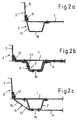
- Querschnittsdarstellung der Verbindung von Radhauslängsträger und Unterboden in Schnittrichtung A-A;
- Figur 2 b
- Querschnittsdarstellung der Verbindung zwischen Radhauslängsträger und Unterboden mit Verstärkungsteil in Schnittrichtung B-B;
- Figur 2 c
- Querschnittsdarstellung der Befestigung von Radhauslängsträger und Unterboden in Schnittrichtung C-C;
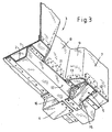
Figur 3- Kraftfahrzeugkarosserie mit einem Verstärkungsteil zwischen Längsträger und Radhaus aus Sicht von unten;
Figur 4- Kräfteverlauf bei Torsionsbeanspruchung; und
Figur 5- die Ansicht einer weitere Ausführung des Verstärkungsteiles.
- FIG. 1
- Motor vehicle body with a reinforcing part and a, provided with a recess wheel arch;
- Figure 2 a
- Cross-sectional view of the connection of the wheel arch side member and underbody in the cutting direction AA;
- FIG. 2 b
- Cross-sectional view of the connection between Radhauslängsträger and underbody with reinforcement in the cutting direction BB;
- Figure 2 c
- Cross-sectional view of the attachment of the wheel arch side member and underbody in the cutting direction CC;
- FIG. 3
- Motor vehicle body with a reinforcement part between the longitudinal member and wheel arch from below view;
- FIG. 4
- Force distribution under torsional stress; and
- FIG. 5
- the view of another embodiment of the reinforcing member.
In Figur 1 ist ein Ausschnitt einer Kraftfahrzeugkarosserie mit einem Unterboden 1, einem Längsträger 2 und einem Querträger 4 zu erkennen. Der Längsträger 2 dient, wie auch der Querträger 4 der Versteifung der Karosserie, wobei der Längsträger 2 in Längsrichtung des Kraftfahrzeuges verläuft und der Querträger 4 quer zur Fahrtrichtung. Der Längsträger 2, wie auch der Querträger 4 sind nach oben hin vom Unterboden 1 abgedeckt, so daß diese vom Fahrzeuginnenraum her nicht zu sehen sind. Vom Unterboden 1 erstreckt sich im wesentlichen nach oben das Radhaus 3. Im Radhaus 3 ist eine Ausbuchtung vorgesehen, in der das gestrichelt dargestellte Feder- bzw. Dämpferbein 6 aufgenommen ist. Der Längsträger 2 ist im Bereich des Radhauses 3 mit einem hochstehenden Schweißflansch 11 versehen, an dem das Radhaus 3 mit der Fläche 8 im Bereich der Unterseite mittels Punktschweißungen befestigt ist.FIG. 1 shows a detail of a motor vehicle body with an
Durch die Ausbuchtung ist die Oberfläche des Radhauses 3 in einer parallel zur Fahrzeuglängsrichtung verlaufende innere Fläche 8 unterteilt, von der sich dann winklig die quer zur Fahrzeuglängsrichtung erstreckende Fläche 9 stufenförmig absetzt. Die Oberfläche des Radhauses 3 geht dann von der quer zur Fahrzeuglängsrichtung verlaufenden Fläche 9 in eine wiederum parallel zur Fahrzeuglängsrichtung verlaufende äußere Fläche 7 über, wobei die Fläche 7- in Fahrtrichtung gesehen - sowohl vor als auch hinter der Ausbuchtung liegen kann.Through the bulge, the surface of the
Am Unterboden 1 sind weiterhin hochstehende Schweißflansche 12 und 13 vorgesehen, die im unteren Bereich des Radhauses 3 an den Flächen 7 und 9 anliegen. Zur Versteifung der Kraftfahrzeugkarosserie ist ein Verstärkungsteil 5 vorgesehen, das am Radhaus 3 im unteren Bereich der äußeren Fläche 7 befestigt ist. Es ist W-förmig ausgebildet und auf dem Unterboden 1, der Seitenwand 17 und der Unterseite 16 des Längsträgers 2 befestigt. Damit ist die äußere Fläche 7 neben einer Verbindung mit dem Unterboden 1 zusätzlich kraftschlüssig mit dem Längsträger 2 verbunden.At the
Das Verstärkungsteil 5 ist in vorteilhafter Weise im Bereich der Verbindung von Längsträger 2 und Querträger 4 am Längsträger 2 befestigt. Auf diese Weise ergibt sich ein besonders steifer Verbindungsknoten gebildet durch den Querträger 4, Längsträger 2 und dem Radhaus 3 verbunden durch das Verstärkungsteil 5. Neben der vorteilhaften Verringerung des Scharniereffektes zwischen dem Radhaus 3 und dem Unterboden 1 wird durch das Verstärkungsteil . 5 eine zusätzliche Möglichkeit geschaffen, Kräfte aus dem Radhaus 3 in den Längsträger 2 einzuleiten.The reinforcing
In Figur 2 a bis 2 c ist die Befestigung des Radhauses 3 an dem Längsträger 2 und dem Unterboden 1 in Querschnittsdarstellung zu erkennen. In Figur 2 a ist die Befestigung des Radhauses 3 in Schnittrichtung A-A im Bereich der sich in Längsrichtung erstreckenden inneren Fläche 8 dargestellt. Der Längsträger 2 weist auf seiner dem Radhaus 3 zugewandten Seite einen hochstehenden Schweißflansch 11 auf, an dem das Radhaus 3 an der inneren Fläche 8 durch Punktschweißungen befestigt ist. Auf der vom Radhaus 3 abgewandten Seite weist der Längsträger 2 einen im wesentlichen horizontalen Flansch auf, auf dem der Unterboden 1 ebenfalls mittels Punktschweißungen befestigt ist. Der Unterboden 1 deckt den Längsträger 2 zum Fahrzeuginnenraum hin ab und ist an seinem, dem Radhaus zugewandten, Ende zu einem Schweißflansch hochgebogen. Der Unterboden 1 ist dann ebenfalls durch Punktschweißungen an dem hochstehenden Schweißflansch 11 des Längsträgers 2 befestigt und damit mittelbar auch an dem Radhaus 3. Durch den hochstehenden Schweißflansch 11 werden während des Fahrbetriebes auftretende Kräfte aus dem Radhaus 3 in den Längsträger 2 eingeleitet.In Figure 2 a to 2 c, the attachment of the
In Figur 2 b ist die Befestigung von Radhaus 3 und Längsträger 2 im Bereich des Verstärkungsteiles 5 in Schnittrichtung B-B zu erkennen. Am Längsträger 2 ist auf der vom Radhaus 3 abgewandten Seite der Querträger 4 an der Unterseite des Längsträgers 2 mittels Punktschweißungen befestigt. Auf der dem Radhaus 3 zugewandten Seite des Längsträgers 2 ist an dessen Unterseite 16 das Verstärkungsteil 5 angeordnet. Das Verstärkungsteil 5 ist W-förmig ausgebildet und an der Unterseite 16 und der Seitenwand 17 des Längsträgers 2 durch Punktschweißungen befestigt. Nach oben hin weist das Verstärkungsteil 5 zunächst einen in Richtung des Unterbodens 1 verlaufenden Abschnitt auf und endet schließlich in einen hochstehenden Schweißflansch, der zusammen mit dem Schweißflansch 12 des Unterbodens 1 am unteren Bereich des Radhauses 3 auf der Fläche 7 mittels Punktschweißungen befestigt ist. Nach oben hin ist die gesamte Verbindung aller Teile durch den Unterboden 1 abgedeckt.In Figure 2 b, the attachment of the
In Figur 2 c ist die Befestigung des Verstärkungsteiles 5 am Längsträger 2 und Radhaus 3 in Schnittrichtung C-C zu sehen. In diesem Bereich des Befestigungsteiles 5 wurde die W-förmige Struktur aufgegeben und durch eine direkte Verbindung mittels eines Abschnittes 15, der sich vom unteren Bereich des Radhauses 3 zur Unterseite 16 des Längsträgers 2 erstreckt. Damit liegt das Verstärkungsteil 5 nicht mehr an der Seitenwand 17 des Längsträgers 2 und dem Unterboden 1 an, sondern stellt die direkte Verbindung zwischen der äußeren Fläche 7 des Radhauses 3 und Unterseite 16 des Längsträger 2 her. Das Verstärkungsteil 5 ist damit unterteilt in einen W-förmigen Randbereich, der an der Unterseite 16 und der Seitenwand 17 des Längsträgers 2 und dem Unterboden 1 und dem Radhaus 3 anliegt und zur Befestigung des Verstärkungsteiles 5 selbst dient, und einen Abschnitt 15, der die direkte Verbindung von Radhaus 3 und Längsträger 2 herstellt.In Figure 2 c, the attachment of the reinforcing
In Figur 3 ist ein Ausschnitt der Kraftfahrzeugkarosserie im Bereich des Verstärkungsteiles 5 zwischen Radhaus 3 und Längsträger 2 von der Unterseite her zu erkennen. An der Unterseite des Längsträgers 2 ist sowohl der Querträger 4 als auch das Verstärkungsteil 5 durch Punktschweißungen befestigt. In seinem weiteren Verlauf ist das Verstärkungsteil 5 mit seinen Rändern an der Seitenwand 17, dem Unterboden 1 und dem Radhaus 3 durch Punktschweißungen befestigt. Etwa mittig ist an dem Verstärkungsteil 5 ein Abschnitt 15 vorgesehen, der nicht mehr an der Seitenwand und dem Unterboden 1 anliegt, sondern das Radhaus 3 direkt mit der Unterseite 16 des Längsträgers 2 verbindet.FIG. 3 shows a detail of the motor vehicle body in the region of the
Die Anordnung des Verstärkungsteiles 5 an der Unterseite des Längsträgers 2 und dem Unterboden 1 bieten den Vorteil, daß das Teil nicht in den Fahrzeuginnenraum ragt. Wesentlicher Vorteil der Anordnung ist, daß im Fertigungsprozeß die Teile ohne erhöhten Aufwand zusammengefügt werden, indem Querträger 4, Längsträger 2, und Verstärkungsteil 5 durch Punktschweißungen in einer Unterbaugruppe miteinander befestigt werden und anschließend das Radhaus 3 und der Unterboden 1 von oben angefügt werden kann. Das Setzen der Punktschweißverbindungen zwischen Radhaus 3 und Unterboden bzw. Verstärkungsteil 5 bereitet keine Schwierigkeiten und kann in gewohnter Weise mit einer Schweißzange erfolgen, die entweder durch die hintere Türöffnung oder durch die Hecklappenöffnung greift. Im Gegensatz zum Stand der Technik sind also für das Verstärkungsteil keine nachträglichen, zusätzlichen Schweißoperationen notwendigThe arrangement of the reinforcing
Die Bemessung des Verstärkungsteiles 5 erfolgt aus Gesichtspunkten der Versteifung, wobei dem direkten Abschnitt 15 besondere Bedeutung zukommt. Neben der Versteifung der Kraftfahrzeugkarosserie um die Längsachse bietet das Verstärkungsteil 5 den weiteren Vorteil, daß an einer zusätzlichen Stelle Kräfte aus dem Radhaus 3 in den Längsträger2 eingeleitet werden können, so daß die Krafteinleitung besser verteilt wird und die eigentliche Krafteinleitungstelle am Schweißflansch 11 nicht übermäßig beansprucht wird.The dimensioning of the reinforcing
Die Krafteinleitung aus dem Federbein in die Unterbodengruppe erfolgt im unteren Bereich der Flächen 9 und 8 mittels hochstehender Schweißflansche 11 und 12 und damit möglichst dicht am Federbein 6, so daß mögliche Biegespannungen reduziert bzw. minimiert werden. Das Federbein 6 selbst besteht üblicherweise aus einer Feder und einem in der Feder angeordneten Stoßdämpfer, der hier jedoch nicht dargestellt ist. Das Feder- bzw. Dämpferbein 6 stützt sich nach oben hin gegen die Unterseite des Radhauses 3 ab und nach unten hin auf einem nicht dargestellten Achsschenkel.The introduction of force from the shock absorber in the subsoil group takes place in the lower region of the
In Figur 4 ist der vereinfachte Kräfteverlauf einer auf das Radhaus wirkenden, idealen Biegemomentbelastung Mt, die u. a. aus einer Torsionsbeanspruchung der Kraftfahrzeugkarosserie resultiert, dargestellt. Über die Verbindung mit dem Verstärkungsteil 5 zum Unterboden 1 wirkt das Moment Mt entsprechend entgegengesetzt im Querträger 4. Vereinfacht dargestellt wird das Moment Mt über die Kräftepaare F QI und F QII im Querträger und die Kräfte F RI und F RII im Radhaus. Aufgabe des Verstärkungsteiles 5 und dabei insbesondere des Abschnittes 15 ist es, die Kraft F RI umzulenken auf die Kraft F QII, was dargestellt wird durch die im Abschnitt 15 wirkenden Zugkräfte F BI bzw. F BII. Bei entgegengesetzter Torsionsbeanspruchung Mt drehen sich die Kräfte in ihrer Richtung um. Das Verstärkungsteil 5 und insbesondere der Abschnitt 15 wirken für die Verbindung zwischen Radhaus 3, Unterboden 1 und Längsträger 2 stabilisierend und vermindern so den Schamiereffekt zwischen Radhaus 3 und Unterboden 1 durch die Stützwirkung des Abschnittes 15.FIG. 4 shows the simplified force curve of an ideal bending moment load Mt acting on the wheel house, which results inter alia from a torsional stress on the motor vehicle body. Through the connection with the reinforcing
Figur 5 zeigt eine weitere Ausführung des Verstärkungsteiles 5, bei der die quer verlaufende Fläche 9 geradlinig mit der Stegfläche 21 des Verstärkungsteiles verbunden ist. Die Funktion des Abschnittes 15 bleibt dabei vollständig erhalten, und zusätzlich wird eine noch bessere Anbindung des Radhauses 3 an den Unterboden 1 über die Stegfläche 21 erreicht.Figure 5 shows a further embodiment of the reinforcing
Weiterhin ist gezeigt die direkte Anbindung der inneren Fläche 8 des Radhauses 3 an die Flanschfläche 22 des Verstärkungsteiles. Auf diese Weise kann auf den hochstehenden Schweißflansch 11 des Längsträgers 2 verzichtet werden; dessen Funktion wird von der Flanschfläche 22 übemommen.Furthermore, it is shown the direct connection of the
Claims (13)
- Motor vehicle body with a wheel house (3), which is arranged at the rear in the direction of travel and is connected to an underbody (1), and a through-loading opening, which is provided in the region of the wheel house (3), and a suspension strut or shock-absorber strut (6) arranged in the wheel house (3), the wheel house (3) having a projection in the region of the suspension strut or shock-absorber strut (6) and the underbody (1) having a longitudinal member (2) adjacent to the wheel house (3), with an outer surface (7) which is spaced apart from the longitudinal member (2) being produced on the wheel house (3) by the projection, characterized in that a reinforcing part (5) is provided between the spaced-apart, outer surface (7) and the longitudinal member (2), the reinforcing part (5) being fastened frictionally in the lower region of the outer surface (7) and to the lower side (16) of the longitudinal member (2).
- Motor vehicle body according to Claim 1, characterized in that the longitudinal member (2) is upwardly open in a U-shaped manner in cross section and the reinforcing part (5) is of W-shaped design and bears against the lower side (16) and the side wall (17) of the longitudinal member (2), the underbody (1) and wheel house (3).
- Motor vehicle body according to either of Claims 1 and 2, characterized in that the longitudinal member (2) is provided with an elevated welding flange (11) in the region of the projection, and in that the wheel house (3) is fastened to the welding flange (11) by way of an inner surface (8) extending in the direction of the welding flange (11).
- Motor vehicle body according to one of Claims 1 to 3, characterized in that at least two surfaces (7, 8) running essentially in the direction of travel and at least one surface (9) running essentially transversely with respect to the direction of travel are formed by the projection in the wheel house (3).
- Motor vehicle body according to one of the preceding claims, characterized in that a crossmember (4) is provided which is connected to the longitudinal member (2), and in that the reinforcing part (5) is fastened to the longitudinal member (2) and/or the crossmember (4) in the region of the point at which the longitudinal member (2) and crossmember (4) are connected.
- Motor vehicle body according to one of the preceding claims, characterized in that the reinforcing part (5) is upwardly covered at least in some sections by the underbody (1) in the region of the connection to the longitudinal member (2) and/or crossmember (4).
- Motor vehicle body according to one of the preceding claims, characterized in that the reinforcing part (5) has a section (15) which extends directly from the wheel house (3) to the lower side (16) of the longitudinal member (2).
- Motor vehicle body according to one of the preceding claims, characterized in that the transversely running surface (9) of the wheel house (3) is directly connected to a web surface (21) of the reinforcing part (5).
- Motor vehicle body according to one of the preceding claims, characterized in that the inner surface (8) of the wheel house (3) is directly connected to a flange surface (22) of the reinforcing part (5).
- Motor vehicle body according to one of the preceding claims, characterized in that the reinforcing part (5) is arranged in front of the projection - as seen in the direction of travel.
- Motor vehicle body according to one of Claims 1 to 9, characterized in that the reinforcing part (5) is arranged behind the projection - as seen in the direction of travel.
- Motor vehicle body according to one of Claims 1 to 9, characterized in that the reinforcing part (5) is of single-piece design and extends in front of and behind the projection - as seen in the direction of travel.
- Motor vehicle body according to Claim 12, characterized in that the reinforcing part (5) has at least two sections (15) which connect the outer surfaces (7) of the wheel house (3) directly to the longitudinal member (2).
Priority Applications (3)
| Application Number | Priority Date | Filing Date | Title |
|---|---|---|---|
| DE50109497T DE50109497D1 (en) | 2001-07-05 | 2001-07-05 | Automotive body |
| EP01116270A EP1273502B1 (en) | 2001-07-05 | 2001-07-05 | Motor vehicle body |
| US10/187,871 US6648401B2 (en) | 2001-07-05 | 2002-07-03 | Motor vehicle body with wheelhouse/underbody reinforcement |
Applications Claiming Priority (1)
| Application Number | Priority Date | Filing Date | Title |
|---|---|---|---|
| EP01116270A EP1273502B1 (en) | 2001-07-05 | 2001-07-05 | Motor vehicle body |
Publications (2)
| Publication Number | Publication Date |
|---|---|
| EP1273502A1 EP1273502A1 (en) | 2003-01-08 |
| EP1273502B1 true EP1273502B1 (en) | 2006-04-12 |
Family
ID=8177942
Family Applications (1)
| Application Number | Title | Priority Date | Filing Date |
|---|---|---|---|
| EP01116270A Expired - Lifetime EP1273502B1 (en) | 2001-07-05 | 2001-07-05 | Motor vehicle body |
Country Status (3)
| Country | Link |
|---|---|
| US (1) | US6648401B2 (en) |
| EP (1) | EP1273502B1 (en) |
| DE (1) | DE50109497D1 (en) |
Families Citing this family (26)
| Publication number | Priority date | Publication date | Assignee | Title |
|---|---|---|---|---|
| JP2004106704A (en) * | 2002-09-18 | 2004-04-08 | Fuji Heavy Ind Ltd | Front body structure of automobile |
| JP4168812B2 (en) * | 2003-04-07 | 2008-10-22 | 三菱自動車工業株式会社 | Connecting structure at the rear of the car body |
| KR100527119B1 (en) * | 2003-04-15 | 2005-11-09 | 현대자동차주식회사 | Stiffness increasing structure of front end module combination area on automobile fender apron |
| US6830287B1 (en) * | 2003-07-24 | 2004-12-14 | Ford Global Technologies, Llc | Rear rail neutralizing member |
| CN100358769C (en) * | 2003-10-07 | 2008-01-02 | 本田技研工业株式会社 | Vehicle rear body structure |
| US7080868B2 (en) * | 2004-11-12 | 2006-07-25 | Honda Motor Co., Ltd. | Rear pillar construction |
| US7401849B2 (en) * | 2004-11-12 | 2008-07-22 | Honda Motor Co., Ltd. | Tower structure supporting bed on frame |
| US7766416B2 (en) * | 2004-11-12 | 2010-08-03 | Honda Motor Co. Ltd. | Wall structure of vehicle frame between cab and load-carrying bed |
| DE602006000068T2 (en) * | 2005-04-15 | 2007-12-13 | Honda Motor Co., Ltd. | Floor structure of a vehicle body |
| JP4268597B2 (en) * | 2005-05-09 | 2009-05-27 | 本田技研工業株式会社 | Rear body structure of automobile |
| US7854472B2 (en) * | 2007-10-22 | 2010-12-21 | Honda Motor Co., Ltd. | Vehicle body structure |
| DE102008031342B4 (en) * | 2008-07-02 | 2021-07-15 | Bayerische Motoren Werke Aktiengesellschaft | Motor vehicle with a loading opening |
| KR100925959B1 (en) * | 2008-08-06 | 2009-11-09 | 현대자동차주식회사 | Rear car body structure of vehicle |
| US7841652B2 (en) * | 2008-11-28 | 2010-11-30 | Ford Global Technologies, Llc | Wheelhouse inner bracket for automotive vehicles |
| JP5337184B2 (en) * | 2011-03-04 | 2013-11-06 | 本田技研工業株式会社 | Car body rear structure |
| JP5769081B2 (en) * | 2011-10-12 | 2015-08-26 | スズキ株式会社 | Bulkhead structure for side members |
| JP2013166474A (en) * | 2012-02-15 | 2013-08-29 | Toyota Motor Corp | Vehicle side section structure |
| KR101428273B1 (en) * | 2012-12-12 | 2014-08-07 | 현대자동차주식회사 | Reinforcing structure of package tray side member for vehivcle |
| KR101484221B1 (en) * | 2013-06-19 | 2015-01-16 | 현대자동차 주식회사 | Rear shock absorber mounting structure for vehicle |
| DE102013219288A1 (en) * | 2013-09-25 | 2015-03-26 | Volkswagen Aktiengesellschaft | Body structure for a vehicle |
| DE102015100263B3 (en) * | 2015-01-09 | 2016-03-31 | Audi Ag | Structural component for a body of a passenger car |
| US9701182B1 (en) * | 2016-02-24 | 2017-07-11 | Toyota Motor Engineering & Manufacturing North America, Inc. | Door reinforcement beam catch projections for vehicle side structures |
| US20180065683A1 (en) * | 2016-09-07 | 2018-03-08 | Thunder Power New Energy Vehicle Development Company Limited | Rear shock tower |
| US10647362B2 (en) * | 2017-03-27 | 2020-05-12 | Mazda Motor Corporation | Rear vehicle-body structure of vehicle |
| US11247733B2 (en) | 2020-07-17 | 2022-02-15 | Toyota Motor Engineering & Manufacturing North America, Inc. | Deforming wheelhouse structure for a vehicle |
| KR20220055292A (en) * | 2020-10-26 | 2022-05-03 | 현대자동차주식회사 | Rear side structure for vehicle |
Family Cites Families (8)
| Publication number | Priority date | Publication date | Assignee | Title |
|---|---|---|---|---|
| JPS5863168U (en) * | 1981-10-23 | 1983-04-27 | マツダ株式会社 | car body structure |
| JPS58128970A (en) * | 1982-01-27 | 1983-08-01 | Mazda Motor Corp | Construction of car body |
| JPH02147480A (en) * | 1988-11-29 | 1990-06-06 | Nissan Motor Co Ltd | Car body structure |
| JPH05338558A (en) * | 1992-06-08 | 1993-12-21 | Toyota Autom Loom Works Ltd | Fitting structure of reinforcing member for automobile |
| JPH06166385A (en) * | 1992-11-30 | 1994-06-14 | Suzuki Motor Corp | Fitting structure or rear floor |
| JP3553578B2 (en) * | 1997-04-01 | 2004-08-11 | スズキ株式会社 | Seat back mounting structure for vehicle seats |
| JP3514966B2 (en) * | 1998-01-13 | 2004-04-05 | ダイハツ工業株式会社 | Support structure for rear wheel suspension |
| JP3866415B2 (en) * | 1998-06-15 | 2007-01-10 | 富士重工業株式会社 | Body structure |
-
2001
- 2001-07-05 EP EP01116270A patent/EP1273502B1/en not_active Expired - Lifetime
- 2001-07-05 DE DE50109497T patent/DE50109497D1/en not_active Expired - Fee Related
-
2002
- 2002-07-03 US US10/187,871 patent/US6648401B2/en not_active Expired - Fee Related
Also Published As
| Publication number | Publication date |
|---|---|
| US20030042762A1 (en) | 2003-03-06 |
| EP1273502A1 (en) | 2003-01-08 |
| DE50109497D1 (en) | 2006-05-24 |
| US6648401B2 (en) | 2003-11-18 |
Similar Documents
| Publication | Publication Date | Title |
|---|---|---|
| EP1273502B1 (en) | Motor vehicle body | |
| DE102009035219B4 (en) | Frame structure of a vehicle and method for providing the same | |
| EP1525132B1 (en) | Floor-supporting arrangement in motor vehicles | |
| DE102005044908B4 (en) | Rear-side vehicle body structure | |
| DE60123723T2 (en) | Subframe for motor vehicles | |
| EP1490256B1 (en) | Motor vehicle | |
| DE3622188C2 (en) | Connection structure between front pillars and a front wall in a vehicle | |
| DE19948363B4 (en) | Central pillar structure | |
| EP2477875B2 (en) | Support frame for a motor vehicle | |
| EP1840003B1 (en) | Door sill reinforcing element for a car body | |
| EP1240065A1 (en) | Vehicle body comprising a bracing arrangement on the bottom side | |
| EP1268261B1 (en) | Vehicle body base | |
| DE102006013548A1 (en) | Chassis sub-frame e.g. axle carrier, for motor vehicle, has bar attached to sub frame-longitudinal carriers such that loading path of sub-frame is bifurcated into loading paths for longitudinal carriers and for longitudinal bar | |
| DE4209879A1 (en) | Front part of motor vehicle bodywork - has side members which also serve to stiffen wheel arches | |
| DE102009042060A1 (en) | Structural component for the rear frame structure of a motor vehicle | |
| DE19843024C2 (en) | Reinforcement for a self-supporting body of a motor vehicle | |
| DE102009059827A1 (en) | Body structure for motor vehicles | |
| DE19605283A1 (en) | Trailing link suspension for vehicles | |
| DE10047880A1 (en) | Suspension frame for motor vehicles, has engine mounting base in which cylinder is pierced, and reinforcement arm is fixed diagonally along cross-section and welded with upper plate and lower plate | |
| DE102009004886B4 (en) | body structure | |
| DE102006014983A1 (en) | Cross member structure for a seating area of a vehicle | |
| EP1562819B1 (en) | Front-end vehicle structure | |
| DE19809279A1 (en) | Chassis of a heavy commercial vehicle | |
| EP1116641A2 (en) | Front structure for a motor vehicle | |
| EP2163401B1 (en) | Axle body for a vehicle axle, especially a rigid axle for a motor and/or commercial vehicle |
Legal Events
| Date | Code | Title | Description |
|---|---|---|---|
| PUAI | Public reference made under article 153(3) epc to a published international application that has entered the european phase |
Free format text: ORIGINAL CODE: 0009012 |
|
| AK | Designated contracting states |
Kind code of ref document: A1 Designated state(s): AT BE CH CY DE DK ES FI FR GB GR IE IT LI LU MC NL PT SE TR |
|
| AX | Request for extension of the european patent |
Free format text: AL;LT;LV;MK;RO;SI |
|
| 17P | Request for examination filed |
Effective date: 20030708 |
|
| AKX | Designation fees paid |
Designated state(s): DE FR GB |
|
| 17Q | First examination report despatched |
Effective date: 20031016 |
|
| GRAP | Despatch of communication of intention to grant a patent |
Free format text: ORIGINAL CODE: EPIDOSNIGR1 |
|
| RAP1 | Party data changed (applicant data changed or rights of an application transferred) |
Owner name: FORD GLOBAL TECHNOLOGIES, LLC |
|
| GRAS | Grant fee paid |
Free format text: ORIGINAL CODE: EPIDOSNIGR3 |
|
| GRAA | (expected) grant |
Free format text: ORIGINAL CODE: 0009210 |
|
| AK | Designated contracting states |
Kind code of ref document: B1 Designated state(s): DE FR GB |
|
| REG | Reference to a national code |
Ref country code: GB Ref legal event code: FG4D Free format text: NOT ENGLISH |
|
| RAP2 | Party data changed (patent owner data changed or rights of a patent transferred) |
Owner name: FORD GLOBAL TECHNOLOGIES, LLC. |
|
| REF | Corresponds to: |
Ref document number: 50109497 Country of ref document: DE Date of ref document: 20060524 Kind code of ref document: P |
|
| GBT | Gb: translation of ep patent filed (gb section 77(6)(a)/1977) |
Effective date: 20060727 |
|
| ET | Fr: translation filed | ||
| PLBE | No opposition filed within time limit |
Free format text: ORIGINAL CODE: 0009261 |
|
| STAA | Information on the status of an ep patent application or granted ep patent |
Free format text: STATUS: NO OPPOSITION FILED WITHIN TIME LIMIT |
|
| 26N | No opposition filed |
Effective date: 20070115 |
|
| PGFP | Annual fee paid to national office [announced via postgrant information from national office to epo] |
Ref country code: FR Payment date: 20090708 Year of fee payment: 9 |
|
| PGFP | Annual fee paid to national office [announced via postgrant information from national office to epo] |
Ref country code: DE Payment date: 20090730 Year of fee payment: 9 Ref country code: GB Payment date: 20090612 Year of fee payment: 9 |
|
| GBPC | Gb: european patent ceased through non-payment of renewal fee |
Effective date: 20100705 |
|
| REG | Reference to a national code |
Ref country code: FR Ref legal event code: ST Effective date: 20110331 |
|
| PG25 | Lapsed in a contracting state [announced via postgrant information from national office to epo] |
Ref country code: DE Free format text: LAPSE BECAUSE OF NON-PAYMENT OF DUE FEES Effective date: 20110201 |
|
| REG | Reference to a national code |
Ref country code: DE Ref legal event code: R119 Ref document number: 50109497 Country of ref document: DE Effective date: 20110201 |
|
| PG25 | Lapsed in a contracting state [announced via postgrant information from national office to epo] |
Ref country code: FR Free format text: LAPSE BECAUSE OF NON-PAYMENT OF DUE FEES Effective date: 20100802 |
|
| PG25 | Lapsed in a contracting state [announced via postgrant information from national office to epo] |
Ref country code: GB Free format text: LAPSE BECAUSE OF NON-PAYMENT OF DUE FEES Effective date: 20100705 |