EP0441614A2 - Verfahren und Vorrichtung zur Feststellung eines Schwellpegels in einem Binärmodus-Dokumentenleser - Google Patents
Verfahren und Vorrichtung zur Feststellung eines Schwellpegels in einem Binärmodus-Dokumentenleser Download PDFInfo
- Publication number
- EP0441614A2 EP0441614A2 EP91300975A EP91300975A EP0441614A2 EP 0441614 A2 EP0441614 A2 EP 0441614A2 EP 91300975 A EP91300975 A EP 91300975A EP 91300975 A EP91300975 A EP 91300975A EP 0441614 A2 EP0441614 A2 EP 0441614A2
- Authority
- EP
- European Patent Office
- Prior art keywords
- document
- magnitude
- signal
- scan
- image
- Prior art date
- Legal status (The legal status is an assumption and is not a legal conclusion. Google has not performed a legal analysis and makes no representation as to the accuracy of the status listed.)
- Granted
Links
Images
Classifications
-
- H—ELECTRICITY
- H04—ELECTRIC COMMUNICATION TECHNIQUE
- H04N—PICTORIAL COMMUNICATION, e.g. TELEVISION
- H04N1/00—Scanning, transmission or reproduction of documents or the like, e.g. facsimile transmission; Details thereof
- H04N1/40—Picture signal circuits
- H04N1/403—Discrimination between the two tones in the picture signal of a two-tone original
Definitions
- the present invention relates to document scanners, and more specifically to a method and an apparatus for determining the optimum threshold signal level to be used when a document scanner is operating in the binary mode.
- the document is illuminated during scanning by the use of a line or footprint of light that extends in what is defined as the X direction.
- the line of light moves relative to the document in what is defined as the orthogonal Y direction.
- Light is thus reflected from the document in a line by line or row by row fashion, each document row extending in the X direction.
- high intensity light is reflected from the document's white background PEL areas
- intermediate intensity light is reflected from the document PELS that contain only a portion of the document's image
- low intensities of light are reflected from the document's black image PEL areas.
- the platen may comprise a horizontal, rectangular, transparent glass or glass-like member on which the document is placed in a stationary manner for scanning by a moving light footprint, or the platen may comprise a thin glass strip that is located coincident with a stationary light footprint, and over which the document is moved during scanning.
- the scanner apparatus can be used to either scan the entire document, or to scan an internal portion or window thereof.
- this window area is defined by giving the X and Y coordinates of the window area, referenced to the X-Y coordinate system that is defined by the platen and by movement of the light footprint.
- the scanner device In a second mode of operation of the scanner apparatus, defined herein as the binary mode of operation, the scanner device is best suited to scan a line or a text document, of which a typewritten page of text is an example.
- the analog output from each sensor cell again may span a substantial magnitude range.
- the above mentioned electronic signal processing means must be capable of resolving the various 8-bit bytes that are generated from the analog signals into but one of two binary values, namely into 0 or 1.
- This operation requires the use of a predefined threshold signal magnitude (i.e. a byte magnitude somewhere intermediate the magnitudes 0000,0000 and 1111,1111) against which the various 8-bit sensor cell magnitudes are compared.
- the present invention finds primary utility in scanner apparatus operating in the binary mode.
- the art has provided ways to adjust the threshold level of a binary mode scanner in an attempt to optimize conversion of the document's visual image into a binary electronic image.
- the operator may view a document and make a judgement as to what threshold value to use, which judgement is based upon the average reflectance of the document, or in the case of a scanner having means to view the electronic image, such as a CRT, perhaps the document is scanned in an iterative fashion until a satisfactory result is achieved.
- the present invention provides a document scanner method and apparatus for binary mode document scanning in which the scanner's threshold signal level is dynamically established by making reference to a stored collection, history, or histogram of the various signal magnitudes that are generated by the various PEL tones of one or more document scan lines.
- tone is intended to mean the reflection characteristic of a document PEL.
- scan line and scan row are to be considered synonymous.
- binary mode scanning of a document is intended to mean a mode of operation in which the scan signal magnitude that is generated for each pixel, picture element or PEL of each document scan line is compared to the predefined magnitude of a threshold signal. If the scan signal magnitude is below the threshold signal magnitude, an image signal of one binary state is generated (i.e. either a binary 0 or a binary 1). If the scan signal magnitude is above the threshold signal magnitude, an image signal of the other binary state is generated.
- the present invention finds primary utility when scanning line-type documents, for example., documents containing a human readable text image or line drawing image that is viewed against a background color tone.
- line-type documents for example., documents containing a human readable text image or line drawing image that is viewed against a background color tone.
- the spirit and scope of the invention is not to be limited thereto since the invention finds utility in the binary mode scanning of any document wherein the majority of the PELS within the document contain only the document's background color tone.
- the scan signal magnitude(s) that is provided by the white background, non-image, PEL areas of the document occur the majority of the time within each and every document scan line, and in some scan lines these PEL areas occur all of the time.
- this majority signal is an accurate measurement of the scan contrast that exists between this document's information-carrying black text image and the non-information-carrying white background of the sheet of paper
- scanning of the document is enhanced in accordance with the invention by establishing the magnitude of the threshold signal as a function of the magnitude of this majority signal.
- the invention is not to be limited thereto, since utility is also found in the case of a light-tone image viewed against a dark-tone background.
- the PELS of the document's visual image are converted to a binary electronic image with minimum loss of image content.
- the threshold signal level is continuously established or initialized in the above described manner during the scanning of a document. In this way, a change in background color tone that may occur within the document's scan length is compensated. This feature of the invention will also compensate for other factors that make the document's effective background color tone appear to change, for example a change in scan illumination intensity.
- a further object of the invention is to provide a method and an apparatus whereby the scanner's threshold magnitude is dynamically and periodically adjusted during a document scan, to thereby modify the magnitude of the threshold signal in the event that the effective background color tone of the document changes as the document is scanned.
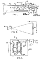
- FIG. 1 A document scanning apparatus 10 embodying the present invention is shown in FIG. 1. While this scanner apparatus is of the general type in which the present invention finds utility, the invention is not limited to the specific arrangement of the apparatus as disclosed.
- scanner apparatus 10 In this scanner apparatus, a document 11 is shown positioned on transparent platen 12 with an image side facing down. The downward facing side of document 11 is scanned so as to convert the visual image contained thereon into an electronic image form that is useable by data processing machines and the like, for example host 45 of FIG. 4.
- scanner apparatus 10 is of the stationary document, moving light source type. However, within the spirit and scope of the invention the scanner apparatus may provide a moving document and a stationary light footprint.
- Document scanning is accomplished in FIG. 1 by movable carriage 15 which contains a linear light source 16 and an array 17 of reflecting mirrors.
- Motor 18, which preferably is a stepping motor, is mechanically coupled to carriage 15 as by means of gears, cables or the like. Motor 18 operates to move carriage 15 bidirectionally along the length of platen 12. Movement to the left in FIG. 1 is defined as scan movement, whereas movement to the right is defined as homing movement. The direction of this movement is defined herein as the Y direction, as is shown in FIG. 1 by an appropriately labeled arrow.
- the light footprint 24 that is reflected from platen 12 is redirected into lens 20, and then into light sensor means 21, best seen in FIG. 3.
- CCD array 27 is of an X direction effective length that is substantially coincident with the length of light footprint 24.
- Light source 16 operates to provide a relatively thin light footprint 24 that spans the X direction or width of platen 12.
- the home position of carriage 15 and light footprint 24 is such that the line of light illuminates the opaque leading edge portion 13 of platen 12.
- light sensor means 21 is preferably a charge coupled device (CCD) assembly or array 27 that is configured as a linear array of individual light sensitive detector cells 28.
- CCD charge coupled device
- Each detector cell 28 of sensor array 27 defines a picture element or pixel (PEL) within the linear scan line that is defined by light footprint 24.
- PEL picture element or pixel
- a typical document scan line footprint 24 (also see FIG. 1), comprising an exemplary length of 3,400 PELS (i.e. 400 PELS per inch of a document that is 8 1/2 inches wide).
- the footprint is optically reduced in length in a predetermined ratio (eg: 7.5:1) upon reaching CCD array 27.
- the analog signal content of light sensor means 21 is periodically read out, document line by document line, as carriage 15 moves in the Y direction along the length of platen 12.
- Controller 22 provides drive signals to carriage motor 18. Controller 22 may operate to control motor 18 in an an open loop or closed loop servo mechanism manner. In a preferred embodiment, controller 22 receives position or movement feedback information relative to carriage 15, such as from the output of a tachometer position detector 23, and receives carriage position feedback from home sensor 59 and from end of scan sensor 90.
- Controller 22 incorporates data processing and handling elements for exchanging data and signals with a remote host or processor 45 (FIG. 4) by way of output cable 14 (43,44 of FIG. 4). The operation of controller 22 is described in greater detail in conjunction with FIG. 4.
- FIG. 3 illustrates an embodiment for reading out the data content of light sensor means 21.
- gating signals typically from controller 22
- the analog signal content of every other detector cell 28 of CCD array 27 is coupled in parallel into analog shift register 25, while the signals present in the other intervening cells 28 are coupled in parallel into analog shift register 26.
- the analog signals loaded into registers 25 and 26 are representative of the various light levels that are reflected from the individual PELS of light footprint 24, as these light levels are received by the like number of individual cells 28 of CCD array 27.
- the individual analog magnitudes correspond to the average of the light quantity that is reflected from a small incremental pixel or PEL of light footprint 24 over a predetermined period of time.
- A/D analog to digital converter
- Output 31 of A/D 30 comprises a sequence of bytes of binary data, for example, one byte of data for each PEL. Each of those bytes corresponds digitally to the magnitude of a discrete one of the analog signals retrieved from shift registers 25 and 26, and thus each byte corresponds to the magnitude of reflected light present at one of the cells 28 of CCD array 27. If array 27 images 400 cells or PELS per inch, output 31 of A/D 30 comprises a similar 400 bytes per inch.
- document 11 is illumination during scanning by the use of light footprint 24 that extends in what is defined as the X direction.
- Light footprint 24 moves relative to document 11 in what is defined as the orthogonal Y direction.
- Light is thus reflected from document 11 in a line by line or row by row fashion, each document row extending in the X direction.
- high intensity light is reflected from the document's white background PEL areas
- intermediate intensity light is reflected from the document PELS that contain only a portion of the document's black image
- low intensities of light are reflected from the document's black image PEL areas.
- a line or footprint of reflected light (24 of FIG. 2) is optically directed onto the linear array of light sensitive cells 28 that effectively extend in the X direction.
- Each individual sensor cell 28 of array 27 defines a document scan column that extends in the Y direction.
- Document scanner 10 is capable of operating in one of two modes of operation.
- the first mode of operation i.e. the default mode of operation
- controller 22 resolves the analog output of each sensor cell 28 into one of a large number of binary values.
- the analog signal output from a sensor cell 28 for a grey scale document 11 is resolved into an 8-bit binary word whose magnitude can span the magnitude range from 0000,0000 to 1111,1111.
- the information content of this 8-bit image signal retains the information content that is present in the document's grey scale image PEL.
- a second mode of operation of scanner apparatus 10 defined herein as the binary mode of operation
- the device is best suited to scan a line document 11, of which a typewritten page of text is an example.
- the analog output from each sensor cell 28 again may span a substantial 8-bit magnitude range.
- controller 22 operates to resolve the various multi level 8-bit bytes into but one of two binary values, namely into 0 or into 1.
- This operation requires the use of a predefined threshold signal magnitude (i.e. a byte whose magnitude is somewhere intermediate the two magnitudes 0000,0000 and 1111,1111) against which the various 8-bit sensor cell magnitudes are compared.
- PELS of an intermediate reflectance characteristic are resolved into one of these two binary states.
- byte 1111,1111 represents the lightest color, highest reflectance shade PEL and byte 0000,0000 represents the darkest color, lowest reflectance shade PEL.
- the threshold signal resolution of mid-shade PELS into a binary image signal is performed so as to minimize loss of the information content of a dark visual image that is viewed against a light background.
- the present invention finds primary utility when scanner apparatus 10 is operating in the binary mode.
- a control input conductor 42 (43 of FIG. 4) places scanner apparatus 10 in its binary mode of operation when an active signal is present on conductor 42.
- Scanner apparatus 10 when in the binary mode of operation, may operate with either a fixed value of threshold signal, or may operate with a threshold signal whose value is periodically and automatically determined in accordance with this invention.
- line type documents of which a typewritten page is an example, are delivered to scanner apparatus 10 for scanning with a very wide variety of background shades, a wide variety of substrate color and thickness, a wide variety of optical transparency, and in a wide variety of conditions that result from improper handling of the documents.
- all of the document parameters that contribute to the document's reflectance characteristics, but do not carry visual information may vary within the body of any single document.
- the present invention provides a method and an apparatus for determining the threshold signal level or magnitude that will be used when scanner apparatus 10 operates in the binary mode with automatic background control selected by use of the control signal(s) present on conductor 42.
- the automatic background control of the present invention is responsive only to the background reflectance level of document 11, and is not responsive to an average reflectance value of the document.
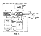
- FIGS. 5-8 Prior to describing the invention in detail with reference to FIGS. 5-8, the general organization of the major electrical and electronic elements associated with the scanning of a full document or a document window will be described with reference to FIG. 4.
- master central processing unit (CPU) 35 controls movement of carriage 15 (FIG. 1) by way of appropriate activation signals on line 33 to motor 18, in conjunction with a carriage position feedback signal that is provided by carriage position tachometer 23 on line 34, and in conjunction with the output of carriage position sensors 59 and 90.
- Sensors 59 and 90 may, for example, comprise a stationary light beam that is momentarily broken by a flag that is mounted on carriage 15.
- master CPU 35 turns on and off the CCD cell sampling, and the analog-to-digital conversion of the cell contents of light sensor means 21, via a two-way control signal dialog that is conducted on lines 36 and 37.
- the digital byte data that is provided by the output of light sensor means 21 (i.e. the output 31 of A/D 30 of FIG. 3) is presented in parallel to slave processor 32 by way of bus 31.
- Processor 36 inserts the bytes of data into storage locations in buffer memory 40 by way of cable 41.
- Slave processor 32 receives and stores the data in response to initiating commands that are received from master CPU 35 via line 38, and continuously informs CPU 35 of its status and operation by way of line 39.
- Slave processor 36 is also in two-way communication with an exemplary remotely located host data handling unit 45 via communication links 43 and 44 (14 of FIG. 1). While parallel bit, multiple line cables provide interface 43,44 between host 45 and slave processor 36, a variety of alternate data transmission disciplines are also available for this purpose, including means such as modems, fiber optic communications, etc.
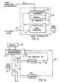
- this figure discloses an embodiment of a binary mode image processor 50 that is contained within slave processor 32 of FIG 4.
- the magnitude of the binary mode threshold signal 54 is set periodically in FIG. 5, for example scan line by scan line, in accordance with the present invention,.
- the 8-bit scan signal output of A/D 30 (FIG. 3) is present on cable or bus 19.
- the binary magnitude of this 8-bit signal may span a decimal value range from 0 to 255.
- This multi-level binary signal is provided as an input to image processor logic network 50.
- Network 50 may include a number of well known image processing and enhancing functions which are not important to the utility of the invention, such as image scaling for example.
- image processor 50 includes image formatting logic network 51 and autobackground processor 52.
- the signal present on line 42 is active.
- processor 52 will operate periodically to analyze the scan byte content of the scan lines of document 11 (for example every document scan line or row) in order to update the signal threshold magnitude that is stored in portion 54 of image formatter 51.
- a default threshold signal is stored in portion 54 and is used during the scanning of document 11.
- formatter 51 operates to compare the magnitude of each scan signal byte on cable 19 to the magnitude of threshold 54, and then operates to provide a binary output, that is bit 0 or bit 1, as a result of that comparison.
- eight such scan PEL bits are packed into one byte, and this packed byte is then placed on output bus 56 (also see 14 of FIG. 1 and 44 of FIG. 4).
- processor 52 Assuming an active signal on line 42, processor 52 continually reads the magnitude of the A/D scan bytes present on cable 19, as these bytes continue to sequentially occur within a predetermined quantity of document scan data, for example within one document line line. The most often occurring individual byte value (or perhaps a range of values) within this predetermined quantity of scan data is then used by processor 52 to establish a threshold magnitude for portion 54 of formatter 51. This threshold magnitude is then used by image formatter 51 to convert scan data 19 to binary magnitudes 56 as the next predetermined quantity of scan data 19 arrives. Also, as this next quantity of scan data arrives, processor 52 again operates to determine a new threshold magnitude for portion 54, if such a new magnitude is in fact required.
- image formatter 51 converts A/D output 19 to one of two binary states using a threshold magnitude 54 that is a function of only the document's background reflectance characteristics, i.e. a function of only the document's most often occurring A/D output on cable 19.
- the embodiment of the invention shown in FIG. 5 provides the utility of updating signal threshold level 54 every time a unit quantity of scan signals 19 are analyzed.
- the unit quantity equals 3,400 scan bytes (i.e. 400 PELS per inch of an 8 1/2 inch document).
- it is usually not necessary to update threshold level 54 on a line by line basis.
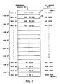
- sixteen memory storage locations 61 of scan signal memory 60 each contain a legend indicating the sixteen scan signal decimal values that are counted by operation of FIG. 6.
- the column to the right of memory locations 61 contains the A/D output bytes on cable 19 that operate to increment the content of the adjacent memory location 61 by one count.
- the lowermost memory location 61 will count the number of scan signal bytes 19 that fall within the decimal value range from "0 to 15", i.e. all sixteen binary bytes within the byte range 0000,XXXX (where X designates the don't care state of a bit).
- all storage locations 61 are initialized to contain a count of 0.
- comparator 64 detects a compare condition (i.e. 0001,0010 is compared to 0001,XXXX) and provides an active output to microprocessor 52 by way of line 66.
- the content of the sixteen memory locations in memory 60 comprises a similar histogram of the overall reflectance characteristic of an 8-scan-line band that extends across document 11 in the X direction.
- microprocessor 52 now interrogates all storage locations 61 in memory 60 and determines which of the storage locations 61 contains the highest count. The value of this highest count is then used to determine a threshold signal value to be placed on line 55. The count contained in all other storage locations 61 is then disregarded, since in accordance with the invention, threshold signal 54 (FIG. 5) of formatter 50 is determined only by the background reflectance characteristic of document 11.
- threshold signal level 54 of FIG. 5 would be set to a value of perhaps 0111,0000 (decimal 112) for the best resolution of the document's black text image.
- all scan byte values on cable 19 that are below the assumed magnitude 0111,0000 would be resolved into a binary output of 0 by image formatter 51 (FIG. 5) for packing into an image byte on line 56 (14 of FIG. 1 and 44 of FIG. 4), and all scan byte values on cable 19 that are above the magnitude 0111,0000 would be resolved into a binary output of 1.
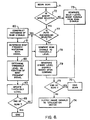
- FIG. 8 discloses a method embodiment of the invention in flow chart form.
- function block 71 consideration of the invention begins with the receipt of a scan request, as from host 45 of FIG. 4, for example.
- Decision block 72 now determines if the binary mode of scanner apparatus 10 has been selected, as by way of an active signal on conductor 42 in FIG. 1.
- function block 73 operates to generate multi level image signals that accurately correspond to the multi level scan signals supplied by A/D output 31 of FIGS 3 and 4 (cable 19 of FIG. 1). These image signals are supplied to a signal utilization device (host 45 of FIG. 1) by operation of function block 74, until such time as the end of a document scan is detected by operation of decision block 75, whereupon the scan operation ends by operation of function block 76.
- the end of a scan operation may be detected, for example by the use of end of scan sensor 90 of FIG. 1, and/or by the use of means including motor position transducer 23, as is well known by those of skill in the art.
- decision block 77 operates to determine if the auto background function has also been selected.
- function block 78 is operable to compare the multi level scan signal magnitudes to a default threshold signal magnitude such as 54 of FIG. 5, and function block 79 thereafter operates to generate binary level image signals that are based upon this signal comparison. These binary level signals are then presented to the signal utilization device, by operation of function block 74, until such time as decision block 75 detects the end of a scan operation, as above mentioned.
- function blocks 78 and 79 operate to provide binary image signals as above described, and in addition, the threshold signal level of function block 78 is periodically updated or reinitialized by the operation of function blocks 80-83.
- the frequency of updating the threshold signal by means of which a binary decision is made relative to the each PEL scan signal may be frequent or infrequent. However, updating preferably occurs a number to times during each document scan.
- function block 80 operates to construct a histogram of a unit quantity of scan signals. From the content of this histogram, function block 81 determines the most frequent scan signal within the histogram. Function block 82 thereafter uses the magnitude of this most frequent scan signal to determine a new threshold signal level. The output of function block 83 is applied to function block 78 in order to effect an update of that function block's threshold level. The output of function block 83 is also applied to function block 80, thereby causing the threshold signal level recalculation to be repeated.
Landscapes
- Engineering & Computer Science (AREA)
- Multimedia (AREA)
- Signal Processing (AREA)
- Image Input (AREA)
- Facsimile Scanning Arrangements (AREA)
- Facsimile Image Signal Circuits (AREA)
- Character Input (AREA)
Applications Claiming Priority (2)
| Application Number | Priority Date | Filing Date | Title |
|---|---|---|---|
| US47728690A | 1990-02-08 | 1990-02-08 | |
| US477286 | 1990-02-08 |
Publications (3)
| Publication Number | Publication Date |
|---|---|
| EP0441614A2 true EP0441614A2 (de) | 1991-08-14 |
| EP0441614A3 EP0441614A3 (en) | 1993-05-05 |
| EP0441614B1 EP0441614B1 (de) | 1997-04-02 |
Family
ID=23895291
Family Applications (1)
| Application Number | Title | Priority Date | Filing Date |
|---|---|---|---|
| EP19910300975 Expired - Lifetime EP0441614B1 (de) | 1990-02-08 | 1991-02-06 | Verfahren und Vorrichtung zur Feststellung eines Schwellpegels in einem Binärmodus-Dokumentenleser |
Country Status (3)
| Country | Link |
|---|---|
| EP (1) | EP0441614B1 (de) |
| JP (1) | JPH04213967A (de) |
| DE (1) | DE69125411T2 (de) |
Families Citing this family (1)
| Publication number | Priority date | Publication date | Assignee | Title |
|---|---|---|---|---|
| JP3334385B2 (ja) * | 1994-12-20 | 2002-10-15 | セイコーエプソン株式会社 | 画像読み取り装置および読み取り方法 |
Family Cites Families (2)
| Publication number | Priority date | Publication date | Assignee | Title |
|---|---|---|---|---|
| US4656665A (en) * | 1985-01-15 | 1987-04-07 | International Business Machines Corporation | Thresholding technique for graphics images using histogram analysis |
| US4916744A (en) * | 1985-12-10 | 1990-04-10 | Fuji Photo Film Co., Ltd. | Image signal processing method |
-
1991
- 1991-02-06 EP EP19910300975 patent/EP0441614B1/de not_active Expired - Lifetime
- 1991-02-06 DE DE1991625411 patent/DE69125411T2/de not_active Expired - Fee Related
- 1991-02-08 JP JP3017711A patent/JPH04213967A/ja active Pending
Also Published As
| Publication number | Publication date |
|---|---|
| EP0441614B1 (de) | 1997-04-02 |
| JPH04213967A (ja) | 1992-08-05 |
| DE69125411T2 (de) | 1997-07-17 |
| EP0441614A3 (en) | 1993-05-05 |
| DE69125411D1 (de) | 1997-05-07 |
Similar Documents
| Publication | Publication Date | Title |
|---|---|---|
| EP0439357B1 (de) | Verfahren und Vorrichtung zur Ausstattung eines Dokumentenlesers mit Sensorkompensation | |
| US5585926A (en) | Document reading apparatus capable of rectifying a picked up image data of documents | |
| EP0239936B1 (de) | Anwahlapparat mit Ansprechalgorithmus | |
| US4554583A (en) | Shading correction device | |
| US4734782A (en) | Image processing apparatus or system with plural reading units, capable of differently processing various areas of an original | |
| US4850029A (en) | Adaptive threshold circuit for image processing | |
| US5201014A (en) | Method and apparatus for establishing threshold level in a binary mode document scanner | |
| JPH04363967A (ja) | 原稿読取り装置 | |
| US4866535A (en) | Method and device for interfacing an image scanner with an image processing device | |
| EP0441614B1 (de) | Verfahren und Vorrichtung zur Feststellung eines Schwellpegels in einem Binärmodus-Dokumentenleser | |
| US7251064B2 (en) | Calibration of an image scanning system | |
| CN1255655A (zh) | 一维cmos图象传感器中光集成过程的自适应定时控制 | |
| EP0439358B1 (de) | Verfahren und Vorrichtung zur Ausstattung eines Dokumentenlesers mit Belichtungskompensation | |
| US6228125B1 (en) | Image processing apparatus for parallel image processing and method therefor | |
| US7443546B2 (en) | Method for generating a calibration curve | |
| JP2946520B2 (ja) | 画像読み取り装置 | |
| US5278667A (en) | Multiple valve image input device | |
| US7583415B2 (en) | Image processing apparatus | |
| EP0195925B1 (de) | Verfahren zum Umwandeln von Bildgraupegeln | |
| JP2000244739A (ja) | 画像読取装置 | |
| US4853793A (en) | Circuit for converting a video signal produced by a line image sensor into a binary signal on the basis of reference levels determined for sections of the line image sensor using respective counters | |
| US6055007A (en) | Image processing device and image reading device | |
| JP3289965B2 (ja) | 赤黒読取装置 | |
| JP3234650B2 (ja) | 赤黒データ読み取り装置 | |
| JPH0310463A (ja) | 画像読取装置 |
Legal Events
| Date | Code | Title | Description |
|---|---|---|---|
| PUAI | Public reference made under article 153(3) epc to a published international application that has entered the european phase |
Free format text: ORIGINAL CODE: 0009012 |
|
| AK | Designated contracting states |
Kind code of ref document: A2 Designated state(s): DE GB |
|
| PUAL | Search report despatched |
Free format text: ORIGINAL CODE: 0009013 |
|
| AK | Designated contracting states |
Kind code of ref document: A3 Designated state(s): DE GB |
|
| 17P | Request for examination filed |
Effective date: 19931014 |
|
| 17Q | First examination report despatched |
Effective date: 19951106 |
|
| GRAG | Despatch of communication of intention to grant |
Free format text: ORIGINAL CODE: EPIDOS AGRA |
|
| GRAH | Despatch of communication of intention to grant a patent |
Free format text: ORIGINAL CODE: EPIDOS IGRA |
|
| GRAH | Despatch of communication of intention to grant a patent |
Free format text: ORIGINAL CODE: EPIDOS IGRA |
|
| GRAA | (expected) grant |
Free format text: ORIGINAL CODE: 0009210 |
|
| AK | Designated contracting states |
Kind code of ref document: B1 Designated state(s): DE GB |
|
| REF | Corresponds to: |
Ref document number: 69125411 Country of ref document: DE Date of ref document: 19970507 |
|
| PLBE | No opposition filed within time limit |
Free format text: ORIGINAL CODE: 0009261 |
|
| STAA | Information on the status of an ep patent application or granted ep patent |
Free format text: STATUS: NO OPPOSITION FILED WITHIN TIME LIMIT |
|
| 26N | No opposition filed | ||
| REG | Reference to a national code |
Ref country code: GB Ref legal event code: 732E |
|
| REG | Reference to a national code |
Ref country code: GB Ref legal event code: IF02 |
|
| PGFP | Annual fee paid to national office [announced via postgrant information from national office to epo] |
Ref country code: GB Payment date: 20050202 Year of fee payment: 15 |
|
| PGFP | Annual fee paid to national office [announced via postgrant information from national office to epo] |
Ref country code: DE Payment date: 20050331 Year of fee payment: 15 |
|
| PG25 | Lapsed in a contracting state [announced via postgrant information from national office to epo] |
Ref country code: GB Free format text: LAPSE BECAUSE OF NON-PAYMENT OF DUE FEES Effective date: 20060206 |
|
| PG25 | Lapsed in a contracting state [announced via postgrant information from national office to epo] |
Ref country code: DE Free format text: LAPSE BECAUSE OF NON-PAYMENT OF DUE FEES Effective date: 20060901 |
|
| GBPC | Gb: european patent ceased through non-payment of renewal fee |
Effective date: 20060206 |