EP0441608B1 - Reproduction photographique d'images par demi-teinte digitale - Google Patents
Reproduction photographique d'images par demi-teinte digitale Download PDFInfo
- Publication number
- EP0441608B1 EP0441608B1 EP91300963A EP91300963A EP0441608B1 EP 0441608 B1 EP0441608 B1 EP 0441608B1 EP 91300963 A EP91300963 A EP 91300963A EP 91300963 A EP91300963 A EP 91300963A EP 0441608 B1 EP0441608 B1 EP 0441608B1
- Authority
- EP
- European Patent Office
- Prior art keywords
- value
- input
- output
- binary
- points
- Prior art date
- Legal status (The legal status is an assumption and is not a legal conclusion. Google has not performed a legal analysis and makes no representation as to the accuracy of the status listed.)
- Expired - Lifetime
Links
Images


Classifications
-
- H—ELECTRICITY
- H04—ELECTRIC COMMUNICATION TECHNIQUE
- H04N—PICTORIAL COMMUNICATION, e.g. TELEVISION
- H04N1/00—Scanning, transmission or reproduction of documents or the like, e.g. facsimile transmission; Details thereof
- H04N1/40—Picture signal circuits
- H04N1/405—Halftoning, i.e. converting the picture signal of a continuous-tone original into a corresponding signal showing only two levels
- H04N1/4055—Halftoning, i.e. converting the picture signal of a continuous-tone original into a corresponding signal showing only two levels producing a clustered dots or a size modulated halftone pattern
- H04N1/4057—Halftoning, i.e. converting the picture signal of a continuous-tone original into a corresponding signal showing only two levels producing a clustered dots or a size modulated halftone pattern the pattern being a mixture of differently sized sub-patterns, e.g. spots having only a few different diameters
Definitions
- This invention is concerned with the reproduction of images, particularly though not exclusively photographic images, and relates to method and apparatus for such purposes.
- the invention has a particular application to a method and apparatus for producing a half-tone image.
- This invention will be described in relation to the reproduction of photographic images, and more particularly, to electronically generating a screened image, which at any point can be either black or white, but not an intermediate gray level.
- Such applications include thermal transfer fax machines, laser electrostatic, and inkjet printers.
- the invention further relates to adjusting the coarseness of the resulting screened image.
- a typical electronic device for reproducing photographic images consists of a scanning module, a screening module, and a marking module.
- the scanning module is used to sense the gray shade of each point of the original photographic image, and report it in electronic form.
- the screening module processes this data into a form suitable for marking. Because many marking devices can only reproduce black or white at any given point, and not intermediate shades of gray, the screening module must generate a screened image containing only black and white points.
- Electronic signals representing the screened image are then routed to the marking module, which marks a medium such as paper or photographic film with the black and white points corresponding to the image generated by the screening module.
- One technique used in a screening module is electronic simulation of a conventional screening technique.
- the conventional technique is described in U.S. Patent US-A-4,498,127, "Screen For Making Photomechanical Printing Plates.”
- a state-of-the art electronic simulation is described in U.S. Patent US-A-4,012,584.
- This technique simulates gray shades by varying the size of the dots.
- the number and position of the dots remains constant.
- this technique suffers two problems. First, the screen patterns are coarse. Second, the number of shades that can be distinguished is small, also causing degradation in the reproduction quality.
- Conventional techniques which vary the size of the dots have not employed adaptive or recursive methods.
- Adaptive dither is another technique that can be used in a screening module. With this technique, gray shades are simulated using very small dots. Lighter shades are represented with fewer dots than darker shades.
- An early example of this technique is given in U.S. Patent US-A-1,790,722 "Duplex photo modulator.” Other popular examples are shown in Floyd, R.W., and L. Steinberg, "An Adaptive Algorithm For Spatial Grayscale", Proc. SID, vol. 17/2, pp. 75-77 and Ulichney, R, "Digital Halftoning", pp. 279-283.
- Adaptive techniques seek to cause an error signal representing the difference between the screened output and the input to approach zero.
- adaptive techniques generate a screened image exhibiting a large number of very small uniform size dots.
- the adaptive technique often provides better detail reproduction, less objectionable patterns, and a larger number of distinguishable shades of gray than the conventional screening technique, it has the further disadvantage of generating screen patterns that are too fine to be well reproduced by most marking devices. This problem is especially severe in reproducing gray shades in the 50% gray region.
- EP-A-0201674 discloses a method for reproducing multi-level divital image on a bi-level printer of fixed dot size.
- the preferred practice of this invention enables me to: provide a photographic reproduction device wherein a large number of gray shades can be distinguished; provide a photographic reproduction device wherein the resulting screening patterns appear pleasing to the eye; provide a photographic reproduction device wherein the resulting screening patterns can be reproduced accurately by common types of marking devices; and vary the size of dots generated by an adaptive technique in photographic reproduction.
- the dots can be produced by marking (e.g.,black) and not marking (e.g., white) the medium storing the image produced. Any printing, electronic, or other storage medium which can represent an image by stored values is within the scope of the invention.
- black and white dots are contemplated, other color dots can also be used within the scope of the invention.
- the resulting irregular placement of the dots significantly improves the number of gray shades which can be produced by the marking device.
- the recursive technique operates in two dimensions and employs a "hysteresis" or adjustable coarseness constant which is used with an error signal to determine the coarseness of the image.
- a photographic reproduction device embodying to the invention has a random access memory (RAM), a scanning device, a screening device which uses the RAM for input, output, and temporary storage of intermediate results, and a marking device.
- the screening device cycles through three phases of operation. In the first phase, image data from the scanning device is stored in an input area of the RAM. During the second phase, the screening patterns are computed, and stored in an output area of the RAM. During the third phase, the resulting screening patterns stored in the output area of the RAM are output to the marking device.
- Each of these phases of operation comprises an iteration through the same number of data elements as there are pixels in one scan line.
- the scanning proceeds left-to-right, then right-to-left, to avoid objectionable diagonal line patterns.
- processing for the screening device can be implemented using a software program running on a general or special purpose computer or can be implemented using special purpose electronic circuitry. Both such implementations would be within the scope of the invention.
- One implementation of the invention provides a photographic image reproducing system comprising: a scanning device receiving an input array i(x,y) corresponding to an original image to be reproduced, wherein x and y represent scanning directions; a marking device receiving output signals o(x,y) from a screening device for marking indicia on an output medium in accordance with said output signals o(x,y); the screening device using said input array i(x,y) in a recurrence relation calculation means, the recurrence relation being:
- a method of producing a halftone image comprising the steps of: scanning a plurality of input points of an original image and generating a numerical value representing a shade of gray for each input point scanned; outputting a screened image having a plurality of dots, each dot of said plurality of dots being one of black or white, the size of each plurality of dots being determined from a recursive relationship between a value of a current input point, a previous output, and an error representing a difference between a value of a previous input point and the previous output; and transmitting signals representing the screened image to a marking device for marking on an output medium.
- the recursive relationship of the preceding paragraph employs a hysteresis constant that determines the coarseness of the screened image.
- the hysteresis constant defines an allowable excursion of the error around zero; the scanning is performed in two dimensions; and the error is allocated in two dimensions, and more particularly is allocated equally in each of the two dimensions.
- x refers to pixels in a scan line
- y refers to the scan lines
- i(x, y) and o(x, y) are the input and output arrays, respectively
- fs is the full scale input value, typically 255 in the cas e of an eight bit array
- h is an hysteresis constant typically of value
- f s may be a value representing a maximum gray shade, being the product of f s and a number not less than zero.
- Fig. 1 shows an error curve for a constant gray shade input from a scanner and corresponding black and white outputs.
- Fig. 2 shows a curve similar to that of Figure 1 with a larger value hysteresis constant.
- Fig. 3 illustrates the quantization effect of measuring discrete points.
- Fig. 4 illustrates scanning according to a serpentine raster procedure.
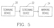
- Fig. 5 is a block diagram of a preferred embodiment of the photographic image reproduction system
- Fig. 6 is a block diagram of the screening device
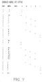
- Fig. 7 is a tabulation of the signals produced by the sequencer module
- Figs. 8-8A are a flowchart describing how a general purpose computer is programmed to carry out the functions of the screening device.
- i(x) is a fraction between 0 and 1 having 256 possible values, with each value representing one of 256 gray shades (e.g., 0 corresponding to white and 255 corresponding to black).
- the gray shades can be represented by 256 integer values ranging from zero (white) to a full scale value, fs, of 255 (black).
- the representations of black and white are arbitrary and can be reversed.
- O(x) is scaled to be an integer between 0 and 255
- the number and size of black and white dots for a given gray shade can be determined, from a recursive relation that considers the effect of the previous output and a secondary error, which itself is a function of the previous error and the current input. Assume that fs represents full scale as discussed above and that e(x) represents an error between inputs i(x) and outputs O(x). In order to obtain a shade of gray at the output that is equal to the shade at the input, it is desired that the average of the differences between the inputs i(x) and outputs O(x), the error, approach zero.
- i(x) can be any integer between zero and 255 while O(x) can take on only the discrete values zero and one, mathematical relationships between i(x) and O(x) must include a scaling for O(x). Thus, on average, the difference between i(x) and the product of O(x) and fs representing full scale must approach zero to achieve the desired effect.
- O(x) is a function of the secondary error e′(x) and the previous output, O(x-1).
- the secondary error e′(x) is a function of the previous error e(x-1) and the input i(x).
- the previous error is a functon of the sums and differences between the inputs i(x) and the outputs O(x).
- the hysteresis constant defines an allowable excursion of the error around zero and thus represents the difference between the output and the input. Over an arbitrarily large number of points the average error, which is e(x) divided by the number of points, approximates zero. Thus, the output gray shade would be approximately equal to the input gray shade.
- Figure 2 illustrates the effect of changing the hysteresis constant h.
- Figure 2 shows that, for the same constant gray shade assumed in Figure 1, an increase in the value of h causes an increase in the size of the white and black dots produced. This is because as h increases it requires a further traversal of the x axis to go up and down the ramp. Thus, fewer transitions from black to white dots occur and the screened image produced is more coarse.
- Figures 1 and 2 show a continuous curve
- Figure 3 more accurately illustrates the case of discrete steps as points x are individually read and processed.
- the quantization is a function of the scanning and does not change the principles of described above.
- One approach to distributing the error is to allocate half the error in each scanning direction.
- x refers to points or pixels in a scan line
- y refers to the scan lines
- i(x, y) and o(x, y) are the input and output arrays, respectively
- fs is the full scale input value, typically 255 in the case of an eight bit array
- h is an adjustable coarseness value typically of value 0.5 times the value of fs and where
- Fig. 5 is a block diagram of a preferred embodiment of an image reproduction device, e.g., a photographic image reproduction device, employing the method according to the invention.
- the photographic reproduction device includes scanning device 20 to measure gray shades of points of an image, convert these measurements to digital form (e.g., 8 bit digital words representing intergers from zero to 255) and transmit them to screening device 22.
- Screening device 22 processes these data, and generates a screen pattern having only two output possible signals, one corresponding to black, and one to white. As previously mentioned, these signals could correspond to marking and not marking a medium for black and white, respectively. In addition, any marking color could be employed. Any of these embodiments are within the scope of the invention described herein.
- the screening device reads sequences of all the points or pixels on one line of the image, then computes the required errors and outputs and generates the corresponding signals to the marking device before moving on to the next line of the image.
- the equations show only one subscript x, defining points of the array.
- the second subscript, y, used in the preceding equations to describe the two dimensional case is accounted for by the line to line scanning.
- e(x) in the flowchart refers to storing error values for only one line, y, of the array e(x,y) at a time.
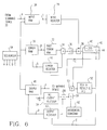
- Figure 6 illustrates an implementation of a screening device in special purpose electronic circuitry.
- the circuitry includes an input register 29, an error register, a past error register 32, an output register 60, and a past output register 54.
- the screening processing device carries out the following sequence of operations:
- the hysteresis constant h affects the coarseness of the patterns formed by the screening device by influencing the size of the dot produced by the marking device.
- a hysteresis constant value of zero corresponds to the finest possible screen.
- a hysteresis constant value of one times the value of full scale fs corresponds to a coarse screen.
- a typical value is 0.5 of full scale, fs, for a screening of medium coarseness. It should be noted however, that h can be any value which is not less than zero.
- Figure 6 shows the connections of a circuit which performs the steps outlined above.
- the screening device 22 has a connection to the scanning device 20 that allows data values to be written to an input RAM 26.
- input RAM 26, error RAM 30 and output RAM 48 could be implemented as portions of a single memory device.
- Another connection from input RAM 26 is used to write a data value read from RAM 26 into input register 28. This activity is triggered by the B output of sequencer 64, as indicated by B on the signal line between input RAM 26 and input register 28.
- Error RAM 30 has a connection to past error register 32, which is used to write a data value read from error RAM 30 into past error register 32. This activity is triggered by the B output of sequencer 64, as indicated by B on the signal line between error RAM 30 and past error register 32. An additional connection is used to store in error RAM 30 the contents of error register 46. This activity is triggered by sequencer 64 output D, as indicated by D on the connection between error RAM 30 and error register 46.
- the contents of past error register 32 and the contents of error register 46 are added together by adder 34.
- the result of this operation is divided by two by divider 36.
- One example of dividing by two is shifting right by one bit position. It will be known to those of ordinary skill that other means of dividing by two are also possible and may be more convenient if, for example, computations are performed in floating point arithmetic. Such approaches are within the scope of the invention described herein.
- the result of this operation is further added to the contents of input register 28 by adder 38. This result is then carried to three other components, which are constant subtractor 40, switch 44 and adder 50.
- Output RAM 48 has a connection to past output register 54, which is used to write a data value read from output RAM 48 into past output register 54. This activity is triggered by the B output of sequencer 64, as indicated by B on the signal line between output RAM 48 and past output register 54. An additional connection is used to store in output RAM 48 the contents of output register 60. This activity is triggered by sequencer 64 output D, as indicated by D on the connection between output RAM 30 and output register 60. A still further connection causes a data value read from output RAM 48 to be sent to the marking device. This activity is triggered by sequencer 64 output E, as indicated by E on the signal line from output RAM 48 to the marking device.
- the output register 60 now stores a 1 if the marking device is to mark a black dot at the location corresponding to the present input pixel.
- the constant 0 is stored into the output register 60, if a white dot is to be placed at the location corresponding to the present input pixel.
- a constant subtractor 40 stores a constant equal to the value of the input corresponding to black to be subtracted from the error register. In a typical case, eight bits are used to represent the input value, so this constant is 28-1, or 255.
- the result from tester 52 is used to switch between the outputs of adder 38 and the constant subtractor 40, the result of which is simply the result of adder 38 from which the constant 255 has been subtracted. If the result from tester 52 is one, then switch 42 will be closed, and a result of constant subtractor 40, triggered by sequencer 64 output C, will be stored in error register 46. If the result of tester 52 is zero, then switch 44 will be closed, and a result of adder 38, again triggered by sequencer 64 output C, will be stored in error register 46.
- Fig. 7 is a tabulation of the signals produced by the sequencer module.
- the sequencer 64 in Fig. 6 has the function of controlling the sequence of operations performed by the screening device circuitry.
- the sequence module generates the address signals for input RAM 26, error RAM 30, and output RAM 48.
- the sequencer module operates in three phases.
- sequencer module 64 signals its output A, for each pixel in the line, while counting the address up from 0. This has the effect of causing a line of data values from scanning device 20 to be stored in input RAM 26.
- the sequencer module will count the address from 0 to n-1, and from n-1 to 0, during alternate invocations of the second phase, where n is understood to be the number of pixels in each scan line. While counting in the second phase, the sequencer module pulses its outputs B, C, and D. Signal B has the effect of loading values from the corresponding RAMs into registers 28, 32, and 54. The loaded values are then processed by the various circuitry discussed above, in order to produce new output and error values. The new output and error values are stored in output register 60 and error register 46, respectively, upon signalling of sequencer 64 output C. Sequencer 64 output D causes the stored values to be finally stored in output RAM 48, and error RAM 30, respectively.
- sequencer 64 counts its address from 0 to n-1, while signalling its E output once for each pixel in the line. This has the effect of transmitting the contents of output RAM 48 to marking device 24.
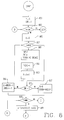
- Figs. 8-8A show a flowchart describing how a general purpose computer can be programmed to carry out the functions of the screening device. It will be obvious to those skilled in the art that the flowchart depicted in Figs. 8-8A is a faithful simulation of the hardware depicted in Fig. 6 and Fig. 7. The flowchart can be implemented by software which can be run on a general purpose computer.
- function block 807 the current value of X is tested to determine if all the points i(x) on line Y have been read. If not, in function block 809 an input is received from the scanning device and in function block 811 the measured value in(x) at point x is stored and X is incremented, as shown in block 813. These steps are repeated until the entire line has been read.
- screen processing begins.
- the direction of the scan is tested as shown in block 815. If the direction is 1, indicating the left to right portion of the scan, X is set equal to zero and a variable endX is set equal to the width of the frame. Otherwise, in block 816, X is set equal to width minus one and endX is set equal to negative one.
- Function block 821 shows a temporary variable T representing an intermediate value which can be stored in a register.
- function block 823 if T is greater than or equal to zero, the output O is set equal to one and the error is set equal to the error minus 255, where 255 represents full scale output, i.e., black, as shown in function blocks 825 and 827. Otherwise the output O is set equal to zero, as shown in function block 829. It will be clear to those of ordinary skill that the variable T and any corresponding temporary storage register can be eliminated by consolidating steps 821 and 823 into a single step. e(x) and o(x) are next set equal to the error and O respectively in block 831. X is incremented in block 833 and the process repeats until the line is completed.
- the recurrence relations could be written in the C programming language, an assembly language of a particular computer, or in another language such as FORTRAN.
Landscapes
- Engineering & Computer Science (AREA)
- Multimedia (AREA)
- Signal Processing (AREA)
- Image Processing (AREA)
- Silver Salt Photography Or Processing Solution Therefor (AREA)
- Holo Graphy (AREA)
- Facsimile Image Signal Circuits (AREA)
- Television Signal Processing For Recording (AREA)
Claims (26)
- Appareil pour reproduire une image d'entrée comme image de sortie constituée par des points de sorties de valeurs binaires, comportant des dispositifs de balayage pour produire une valeur d'entrée respective sur une échelle de grille pour chacun d'une pluralité de points d'entrée de l'image d'entrée et des dispositifs de traitement en réponse aux valeurs d'entrées pour produire une valeur de sortie binaire pour chacun d'une pluralité des points de sortie pour produire l'image de sortie, caractérisé en ce que :
- le dispositif de traitement comporte des moyens de décision (50 - 58) pour décider de la valeur binaire de sortie (O(x)) à accorder à chaque valeur d'entrée (i(x)) sur la base de la valeur d'entrée (i(x)) et d'une valeur d'erreur cumulative (e(x-1)) et des moyens (30 - 46) pour incrémenter la valeur d'erreur cumulative (e(x-1)) en dépendance de la différence entre la valeur d'entrée (i(x)) et la valeur d'échelle de grille de la valeur binaire de sortie (O(x)) dépendant des moyens de décision, lesdits moyens de décision et les moyens d'incrémentation étant arrangés pour fonctionner en une relation de récurence dans laquelle la valeur cumulative d'erreur (e(x)) tend vers une valeur moyenne nulle, les moyens de décision comportant un dispositif de polarisation (54, 60, 62) en réponse à une valeur binaire précédente 0(X-1) pour dévier l'action des moyens de décision dans le sens de ladite valeur binaire de sortie précédente introduisant de ce fait une hysteresis dans les transitions à partir d'une sortie binaire d'une valeur vers une sortie binaire de l'autre valeur. - Appareil selon la revendication 1, dans lequel lesdits points d'entrée forment une matrice bi-dimensionnelle et les moyens de décision répondant à une valeur d'entrée combinée cumulative si l'on répond à une valeur d'entrée combinée cumulative qui comporte deux composantes, une première composante provenant de la valeur de l'erreur cumulative établie par l'opération des moyens d'incrémentation en un point d'entrée immédiatement antérieur sur un premier axe de ladite matrice bi-dimensionnelle et la seconde composante provenant de la valeur cumulative d'erreur établie par ladite opération des moyens d'incrémentation en un point d'entrée immédiatement antérieur sur un second axe de ladite matrice bi-dimensionnelle.
- Appareil suivant la revendication 1, dans lequel ledit dispositif de polarisation produit une valeur de polarisation pour influencer le fonctionnement des moyens de décision, les moyens de polarisation étant le produit d'une constante choisie et de la valeur d'échelle de grille de ladite valeur binaire de sortie antérieure, ladite valeur de polarisation étant fournie auxdits moyens de décision pour être combinée avec ladite valeur d'entrée et ladite valeur cumulative d'erreur dans un sens qui dévie la décision relative à. la valeur binaire de sortie vers ladite valeur binaire antérieure de sortie.
- Appareil suivant les revendications 1 ou 3, dans lequel ledit dispositif de traitement transforme lesdits points d'entrée selon une séquence pré-déterminée et pour chaque valeur d'entrée traitée par lesdits moyens de traitement la valeur binaire de sortie antérieure à laquelle ledit dispositif pour la réalisation répond étant celle correspondant à la valeur d'entrée immédiatement antérieure.
- Appareil suivant l'une des revendications 1, 3 ou 4, dans lequel ledit dispositif de balayage peut fonctionner pour balayer l'image d'entrée en une succession de lignes pour obtenir une matrice bi-dimensionnelle de points d'entrée.
- Appareil suivant la revendication 5, dans lequel les points d'entrée d'une ligne sont traités dans la direction opposée au point d'entrée de la ligne immédiatement suivante.
- Appareil selon la revendication 2, dans lequel ledit dispositif de polarisation produit une valeur de polarisation pour influencer le fonctionnement des moyens de décision, ladite valeur de polarisation étant le produit d'une constante choisie et de la somme des valeurs respectives dans l'échelle des grilles des valeurs binaires de sortie aux points d'entrée immédiatement antérieurs sur ledit premier et ledit second axe, ladite valeur de polarisation étant fournie aux moyens de décision pour être combinée avec ladite valeur d'entrée et ladite valeur cumulative d'erreur combinée en un sens qui dévie la décision relative à la valeur binaire de sortie vers les valeurs binaires de sorties antérieures obtenues pour lesdits points d'entrées immédiatement antérieurs lorsque de telles valeurs binaires de sorties sont les mêmes.
- Appareil suivant la revendication 7, dans lequel ledit dispositif de balayage peut fonctionner pour balayer ladite matrice bi-dimensionnelle comme une succession de lignes s'étendant dans la direction de l'un des axes de la matrice.
- Appareil suivant la revendication 8, dans lequel les points d'entrée sur une ligne sont traités en direction opposée aux points d'entrée situés sur la ligne immédiatement suivante.
- Appareil pour reproduire une image d'entrée comme image de sortie constitué de points de sortie ayant des valeurs binaires comportant un dispositif de balayage pour produire une valeur d'entrée respective sur une échelle de grilles pour une pluralité de points d'entrée sur l'image d'entrée disposée dans une matrice bi-dimensionnelle et des dispositifs de traitement destinés à produire une valeur binaire de sortie pour chacun d'une pluralité des points de sortie pour produire l'image de sortie, caractérisé en ce que :
le dispositif de traitement comporte des moyens de décision pour décider d'une valeur binaire de sortie à accorder à chaque valeur d'entrée sur la base de la valeur d'entrée et d'une valeur cumulative d'erreur provenant des erreurs respectives établies par les deux points pour les deux points d'entrées immédiatement antérieurs de la matrice dans les deux dimensions de celle-ci et des moyens pour incrémenter la : valeur cumulative d'erreur selon la différence entre la valeur d'entrée et la valeur d'échelle de grille de la valeur binaire de sortie accordée à ladite valeur d'entrée, les moyens de décision et les moyens d'incrémentation étant disposés pour fonctionner en relation récurente dans laquelle ladite valeur cumulative d'erreur tend vers une valeur moyenne nulle, les moyens de décision comportant un dispositif de polarisation en réponse à une sortie binaire antérieure respective dans chaque dimension de ladite matrice afin de désigner le fonctionnement des moyens de décision vers lesdites valeurs binaires de sorties antérieures respectives lorsque ces deux valeurs sont les mêmes. - Appareil suivant la revendication 10, dans lequel ledit dispositif de polarisation produit une valeur de polarisation pour influencer le fonctionnement des moyens de décision, ladite valeur de polarisation étant le produit d'une constante choisie et de la somme des valeurs d'échelles de grilles respectives des valeurs binaires de sorties attribuées auxdits points d'entrée immédiatement antérieurs, ladite valeur de polarisation étant fournie auxdits moyens de décision pour être combinée avec ladite valeur d'entrée et ladite valeur cumulative d'erreur dans un sens tel qu'elle fait dévier la valeur de sortie binaire en direction des valeurs binaires des sorties précédentes obtenues pour lesdits deux points immédiatement antérieurs lorsque de telles valeurs binaires de sorties sont les mêmes.
- Appareil suivant l'une quelconque des revendications qui précèdent, comportant en outre un dispositif pour marquer une pluralité de points d'images de sorties sur un moyen d'affichage avec un premier ou un second indice de marquage, ledit dispositif de marquage répondant auxdites valeurs binaires de sorties pour marquer un point image de sortie respectif pour chaque point image d'entrée avec un premier ou un second indice en accord avec la valeur binaire de sortie accordée au point image d'entrée.
- Appareil selon la revendication 12, dans lequel l'un desdits premier et second indice de marquage est constitué par aucune marque excécutée sur le moyen d'affichage.
- Procédé pour reproduire une image d'entrée comme image de sortie constitué par des points de sortie ayant des valeurs binaires, comportant un balayage de l'image d'entrée pour produire une valeur d'entrée respective sur une échelle de grille pour chacun d'une pluralité des points d'entrée sur l'image d'entrée et pour traiter des valeurs d'entrées pour produire une valeur de sortie binaire pour chacun d'une pluralité de point de sortie pour produire l'image de sortie caractérisé en ce que :
le traitement des valeurs d'entrée comporte des étapes de décision sur une valeur binaire de sortie (O(x)) pour être accordée à chaque valeur d'entrée (i(x)) sur la base de la valeur d'entrée (i(x)) et d'une valeur cumulative d'erreur (e(x-1)) et d'incrémentation de la valeur cumulative d'erreur (e(x-1)) en dépendance de la différence entré la valeur d'entrée (i(x)) et de la valeur dans l'échelle des grilles de la valeur binaire de sortie (O(x)) accordée par ladite étape de décision, lesdites étapes de décision et d'incrémentation étant effectuées dans une relation récurente dans laquelle la valeur cumulative d'erreur tend vers une valeur moyenne nulle et ladite étape de décision inclut l'étape de fourniture d'une valeur de polarisation dépendant d'une valeur binaire de sortie antérieure, laquelle valeur de polarisation dévie l'étape de déviation pour l'orienter vers ladite valeur binaire de sortie antérieure, introduisant de ce fait une hysteresis dans les transitions à partir d'une sortie binaire d'une valeur vers une sortie binaire de l'autre valeur. - Procédé suivant la revendication 14, dans lequel lesdits points d'entrée forment une matrice bi-dimensionnelle et ladite étape de décision répond à une valeur d'erreur cumulative combinée ayant deux composantes, une première composante étant dérivée de la valeur d'erreur cumulative établie par ladite étape d'incrémentation en un point d'entrée immédiatement antérieur sur un premier axe de ladite matrice bi-dimensionnelle et la seconde composante étant dérivée de la valeur cumulative d'erreur établie par ladite étape d'incrémentation en un point d'entrée immédiatement antérieur sur un second axe de ladite matrice bi-dimensionnelle.
- Procédé selon la revendication 14, dans lequel ladite valeur de polarisation est le produit d'une constante choisie et la valeur dans l'échelle des grilles d'une valeur binaire de sortie antérieure, ladite valeur de polarisation étant combinée avec ladite valeur d'entrée et ladite valeur cumulative d'erreur dans un sens tel qu'elle dévie la valeur binaire de sortie accordée à ladite valeur d'entrée vers ladite valeur binaire de sortie antérieure.
- Procédé selon la revendication 16, dans lequel lesdits points d'entrée sont traités dans une séquence pré-déterminée et pour chaque valeur d'entrée traitée par ledit dispositif de traitement, la valeur binaire de sortie antérieure est celle accordée avec la valeur d'entrée immédiatement antérieure.
- Procédé suivant l'une quelconque des revendications 14, 16 ou 17, dans lequel ladite image d'entrée est balayée par une succession de lignes pour obtenir une matrice bi-dimensionnelle de point d'entrée.
- Procédé suivant la revendication 18, dans lequel les points d'entrée sur une ligne sont traités dans une direction opposée par rapport au point d'entrée de la ligne immédiatement suivante.
- Procédé suivant la revendication 15, dans lequel ladite valeur de polarisation est le produit d'une constante choisie et de la somme des valeurs respectives dans l'échelle des grilles des valeurs binaires de sortie desdits points d'entrée immédiatement antérieurs sur lesdits premier et second axes, ladite valeur de polarisation étant combinée avec ladite valeur d'entrée et ladite valeur cumulative d'erreur combinée dans un sens qui fait dévier la valeur binaire de sortie accordée à ladite valeur d'entrée en direction des valeurs binaires de sortie antérieure obtenues pour lesdits points d'entrée immédiatement antérieurs lorsque de telles valeurs binaires de sortie sont les mêmes.
- Procédé suivant la revendication 20, dans lequel ladite matrice bi-dimensionnelle est balayée en une succession de lignes s'étendant dans la direction de l'un des axes de la matrice.
- Procédé suivant la revendication 21, dans lequel les points d'entrée sur une même ligne sont traités en une direction opposée au point d'entrée de la ligne immédiatement suivante.
- Procédé pour la reproduction d'une image d'entrée comme image de sortie comprenant des points de sortie ayant des valeurs binaires, comportant un balayage de l'image d'entrée pour produire une valeur d'entrée respective sur une échelle des grilles pour chacun d'une pluralité de points d'entrées sur l'image d'entrée disposée dans une matrice bi-dimensionnelle et un traitement des valeurs d'entrée pour produire une valeur de sortie binaire pour chacun d'une pluralité des points de sortie pour produire l'image de sortie, caractérisée en ce que :
le traitement des valeurs d'entrée comporte des étapes de décision sur une valeur binaire de sortie à accorder à chaque valeur d'entrée sur la base de la valeur d'entrée et d'une valeur cumulative d'erreur dérivée des erreurs cumulatives respectives établies pour les deux points d'entrée immédiatement antérieurs de la matrice dans les deux dimensions de celle-ci et l'incrémentation de la valeur d'erreur cumulative en dépendance de la différence entre la valeur d'entrée et la valeur dans l'échelle des grilles de la valeur de sortie accordée à la valeur d'entrée, ladite étape de décision et ladite étape d'incrémentation étant réalisées en une relation récurente dans laquelle la valeur cumulative d'erreur tend vers une valeur moyenne nulle et ladite étape de décision inclut l'étape de production d'une valeur de polarisation dépendant d'une valeur respective linéaire antérieure dans chacune des deux directions de la matrice, laquelle valeur de polarisation fait dévier l'étape de décision vers lesdites valeurs linéaires de sorties respectives lorsque de telles valeurs sont les mêmes. - Procédé suivant la revendication 23, dans lequel ladite valeur de polarisation est le produit d'une constante choisie et de la somme des valeurs respectives dans l'échelle des grilles des valeurs de sortie couplées auxdits points d'entrée immédiatement antérieurs, ladite valeur de polarisation étant combinée avec ladite valeur d'entrée et ladite valeur cumulative d'erreur dans un sens qui fait dévier la décision de la valeur binaire de la sortie en direction des valeurs de sorties antérieures obtenues pour lesdits deux points d'entrée immédiatement antérieurs lorsque ces deux valeurs binaires de sorties sont les mêmes.
- Procédé suivant l'une quelconque des revendications 14 à 24, comportant en outre l'étape de marquage d'une pluralité de points image de sortie sur un moyen d'affichage avec un premier ou un second indice de marquage, de telle sorte qu'un point image de sortie respectif est marqué pour chaque point image d'entrée par un premier ou un second indice en accord avec la valeur binaire de sortie couplée avec le point image d'entrée.
- Procédé suivant la revendication 25, dans lequel l'un desdits premier ou second indice de marquage est constitué par aucune marque effectuée par le moyen d'affichage.
Applications Claiming Priority (2)
| Application Number | Priority Date | Filing Date | Title |
|---|---|---|---|
| US07/476,060 US5055942A (en) | 1990-02-06 | 1990-02-06 | Photographic image reproduction device using digital halftoning to screen images allowing adjustable coarseness |
| US476060 | 1990-02-06 |
Publications (3)
| Publication Number | Publication Date |
|---|---|
| EP0441608A2 EP0441608A2 (fr) | 1991-08-14 |
| EP0441608A3 EP0441608A3 (en) | 1992-11-25 |
| EP0441608B1 true EP0441608B1 (fr) | 1995-04-19 |
Family
ID=23890343
Family Applications (1)
| Application Number | Title | Priority Date | Filing Date |
|---|---|---|---|
| EP91300963A Expired - Lifetime EP0441608B1 (fr) | 1990-02-06 | 1991-02-06 | Reproduction photographique d'images par demi-teinte digitale |
Country Status (5)
| Country | Link |
|---|---|
| US (2) | US5055942A (fr) |
| EP (1) | EP0441608B1 (fr) |
| JP (1) | JPH04213964A (fr) |
| AT (1) | ATE121581T1 (fr) |
| DE (1) | DE69108951T2 (fr) |
Families Citing this family (31)
| Publication number | Priority date | Publication date | Assignee | Title |
|---|---|---|---|---|
| DE3838730C2 (de) * | 1987-11-16 | 1994-07-28 | Canon Kk | Verfahren und Vorrichtung zur Bildverarbeitung |
| US6134355A (en) * | 1989-02-10 | 2000-10-17 | Canon Kabushiki Kaisha | Binarization using a local average, and using error diffusion |
| US5463472A (en) * | 1991-02-22 | 1995-10-31 | At&T Corp. | Model-based halftoning |
| US5337162A (en) * | 1991-06-30 | 1994-08-09 | Ricoh Company, Ltd. | Image processing apparatus for preventing occurrence of moire in output image |
| US5268774A (en) * | 1991-11-27 | 1993-12-07 | Xerox Corporation | Halftoning with enhanced dynamic range and edge enhanced error diffusion |
| US5331429A (en) * | 1992-02-07 | 1994-07-19 | Levien Raphael L | Digital generation of halftone images with error diffusion and frequency matched periodic screen rulings |
| US5260807A (en) * | 1992-06-05 | 1993-11-09 | Eastman Kodak Company | Method and apparatus for imbedding controlled structure for gray scale rendering |
| US5473439A (en) * | 1992-10-23 | 1995-12-05 | At&T Corp. | Model-based halftoning of color images |
| US5917614A (en) * | 1992-11-30 | 1999-06-29 | Levien; Raphael L | Method and apparatus for error diffusion screening of images with improved smoothness in highlight and shadow regions |
| US5321525A (en) * | 1992-12-14 | 1994-06-14 | Xerox Corporation | Clustered halftoning with dot-to-dot error diffusion |
| US5325211A (en) * | 1993-01-04 | 1994-06-28 | Xerox Corporation | Error diffusion with output and input based feedback |
| US5621546A (en) * | 1993-11-02 | 1997-04-15 | Xerox Corporation | Method and apparatus for vector error diffusion with output color control |
| US5353127A (en) * | 1993-12-15 | 1994-10-04 | Xerox Corporation | Method for quantization gray level pixel data with extended distribution set |
| US5446561A (en) * | 1994-03-08 | 1995-08-29 | Eastman Kodak Company | Method and apparatus for digital scale halftoning with variable screen structure for electrophotographic printing devices |
| US5535019A (en) * | 1994-09-15 | 1996-07-09 | Xerox Corporation | Error diffusion halftoning with homogeneous response in high/low intensity image regions |
| US5594839A (en) * | 1994-10-17 | 1997-01-14 | Seiko Epson Corporation | Apparatus and method for improving black and color separation in halftoned images by printing black dots in a different screen phase |
| JPH08204971A (ja) * | 1994-10-31 | 1996-08-09 | Xerox Corp | 予測符号化と誤差拡散を用いた画像圧縮方法 |
| US5493416A (en) * | 1994-10-31 | 1996-02-20 | Xerox Corporation | Method combining error diffusion and traditional halftoning with arbitrary screen orientation |
| SE9504016L (sv) * | 1995-11-13 | 1997-05-14 | Forskarpatent I Linkoeping Ab | Rastreringsförfarande |
| US5668638A (en) * | 1996-06-27 | 1997-09-16 | Xerox Corporation | Error diffusion method with symmetric enhancement |
| US5701366A (en) * | 1996-09-04 | 1997-12-23 | Canon Information Systems, Inc. | Halftoning with gradient-based selection of dither matrices |
| US6006011A (en) * | 1997-09-03 | 1999-12-21 | International Business Machines Corporation | Target patterns controlled error management |
| US5946455A (en) * | 1997-10-02 | 1999-08-31 | International Business Machines Corporation | Model based error diffusion with correction propagation |
| US6493112B1 (en) | 1998-01-16 | 2002-12-10 | University Of Delaware | Method and apparatus for producing halftone images using green-noise masks having adjustable coarseness |
| US6160921A (en) * | 1998-06-15 | 2000-12-12 | Apple Computer, Inc. | Error diffusion with homogeneous distribution in highlight and shadow regions |
| US6798537B1 (en) | 1999-01-27 | 2004-09-28 | The University Of Delaware | Digital color halftoning with generalized error diffusion vector green-noise masks |
| US6678073B1 (en) | 2000-02-08 | 2004-01-13 | Oak Technology, Inc. | Error diffusion method and apparatus |
| US7161634B2 (en) * | 2003-03-06 | 2007-01-09 | Huaya Microelectronics, Ltd. | Encoding system for error diffusion dithering |
| US8576447B2 (en) * | 2003-10-31 | 2013-11-05 | Hewlett-Packard Development Company, L.P. | Error diffusion halftoning with bandpass noise shaping |
| US7317556B2 (en) * | 2003-12-19 | 2008-01-08 | Xerox Corporation | Method for error diffusion employing a stamp field |
| US7420708B2 (en) | 2003-12-19 | 2008-09-02 | Xerox Corporation | Method for processing color image data employing a stamp field |
Citations (2)
| Publication number | Priority date | Publication date | Assignee | Title |
|---|---|---|---|---|
| EP0201674A2 (fr) * | 1985-04-12 | 1986-11-20 | International Business Machines Corporation | Procédé pour reproduire des images numériques à teintes multiples à l'aide d'une imprimante à deux teintes et à dimension de point fixe |
| DE3838730A1 (de) * | 1987-11-16 | 1989-05-24 | Canon Kk | Verfahren und vorrichtung zur bildverarbeitung |
Family Cites Families (15)
| Publication number | Priority date | Publication date | Assignee | Title |
|---|---|---|---|---|
| US498127A (en) * | 1893-05-23 | Screen for making photomechanical printing-plates | ||
| US1790722A (en) * | 1931-02-03 | Duplex photomointlatob | ||
| GB1495499A (en) * | 1974-01-30 | 1977-12-21 | Crosfield Electronics Ltd | Image reproduction systems |
| US4933776A (en) * | 1983-01-24 | 1990-06-12 | Canon Kabushiki Kaisha | Image processing method and apparatus therefor |
| JPS6062779A (ja) * | 1983-08-31 | 1985-04-10 | Nec Corp | インクジェット記録方法 |
| US4633327A (en) * | 1983-11-10 | 1986-12-30 | Xerox Corporation | Enhancement halftoning |
| US4574357A (en) * | 1984-02-21 | 1986-03-04 | Pitney Bowes Inc. | Real time character thinning system |
| US4651287A (en) * | 1984-06-14 | 1987-03-17 | Tsao Sherman H | Digital image processing algorithm for output devices with discrete halftone gray scale capability |
| US4707745A (en) * | 1984-12-20 | 1987-11-17 | Ricoh Company, Ltd. | Digital copier with document image region decision device |
| JPS6229372A (ja) * | 1985-07-31 | 1987-02-07 | インタ−ナショナル ビジネス マシ−ンズ コ−ポレ−ション | 2値デ−タの圧縮方法 |
| JPS62118676A (ja) * | 1985-11-18 | 1987-05-30 | Sharp Corp | 画像処理方式 |
| US4680645A (en) * | 1986-08-25 | 1987-07-14 | Hewlett-Packard Company | Method for rendering gray scale images with variable dot sizes |
| JP2796718B2 (ja) * | 1988-08-23 | 1998-09-10 | 株式会社ヤマトヤ商会 | 画像の階調変換方法 |
| US5268774A (en) * | 1991-11-27 | 1993-12-07 | Xerox Corporation | Halftoning with enhanced dynamic range and edge enhanced error diffusion |
| US5321525A (en) * | 1992-12-14 | 1994-06-14 | Xerox Corporation | Clustered halftoning with dot-to-dot error diffusion |
-
1990
- 1990-02-06 US US07/476,060 patent/US5055942A/en not_active Expired - Lifetime
-
1991
- 1991-02-06 DE DE69108951T patent/DE69108951T2/de not_active Expired - Fee Related
- 1991-02-06 EP EP91300963A patent/EP0441608B1/fr not_active Expired - Lifetime
- 1991-02-06 JP JP3015257A patent/JPH04213964A/ja active Pending
- 1991-02-06 AT AT91300963T patent/ATE121581T1/de active
-
1994
- 1994-01-19 US US08/183,694 patent/USRE37907E1/en not_active Expired - Lifetime
Patent Citations (2)
| Publication number | Priority date | Publication date | Assignee | Title |
|---|---|---|---|---|
| EP0201674A2 (fr) * | 1985-04-12 | 1986-11-20 | International Business Machines Corporation | Procédé pour reproduire des images numériques à teintes multiples à l'aide d'une imprimante à deux teintes et à dimension de point fixe |
| DE3838730A1 (de) * | 1987-11-16 | 1989-05-24 | Canon Kk | Verfahren und vorrichtung zur bildverarbeitung |
Non-Patent Citations (1)
| Title |
|---|
| PROC OF THE SID, VOL 27/4, 1986 PP 305: "HALFTONING TECHNIQUES USING ERROR CORRECTION"; FAWCETT et al. * |
Also Published As
| Publication number | Publication date |
|---|---|
| DE69108951T2 (de) | 1995-10-05 |
| EP0441608A2 (fr) | 1991-08-14 |
| USRE37907E1 (en) | 2002-11-19 |
| ATE121581T1 (de) | 1995-05-15 |
| DE69108951D1 (de) | 1995-05-24 |
| US5055942A (en) | 1991-10-08 |
| EP0441608A3 (en) | 1992-11-25 |
| JPH04213964A (ja) | 1992-08-05 |
Similar Documents
| Publication | Publication Date | Title |
|---|---|---|
| EP0441608B1 (fr) | Reproduction photographique d'images par demi-teinte digitale | |
| EP0659012B1 (fr) | Procédé de quantification de données d'images à niveaux de gris avec un ensemble étendu de distribution | |
| CA1114746A (fr) | Representation electronique en demi-teintes a orientation variable | |
| EP0717551B1 (fr) | Dispositif de traitement d'image | |
| US4185304A (en) | Electronic halftone screening | |
| EP0639023B1 (fr) | Procédé de fabrication des images de demi-teintes à modulation de fréquence | |
| US4903123A (en) | Image processing apparatus using inclined line screens to reduce Moire | |
| EP0814599A2 (fr) | Tramage en demi-teintes stochastique | |
| US5917614A (en) | Method and apparatus for error diffusion screening of images with improved smoothness in highlight and shadow regions | |
| US5805738A (en) | Image processing apparatus and method | |
| EP0710006B1 (fr) | Appareil de formation d'images capable de produire des images en pseudo demi-teintes par l'utilisation de modèles de tremblement | |
| Lee et al. | Inkjet printer model-based halftoning | |
| JP4236804B2 (ja) | 画像処理方法、その装置及び記憶媒体 | |
| US5289294A (en) | Image processing apparatus | |
| US5493416A (en) | Method combining error diffusion and traditional halftoning with arbitrary screen orientation | |
| US5805724A (en) | Method and system for hybrid error diffusion processing of image information using dynamic screens based on brightness/darkness settings | |
| US5933539A (en) | Method and system for hybrid error diffusion processing of image information using programmable screen modulation | |
| US5822464A (en) | Method and system for processing image information using video dependent dampened screening and error diffusion | |
| US5787206A (en) | Method and system for processing image information using expanded dynamic screening and error diffusion | |
| US5331429A (en) | Digital generation of halftone images with error diffusion and frequency matched periodic screen rulings | |
| EP0342845A1 (fr) | Création d'images en demi-teintes | |
| EP0488324B1 (fr) | Procédé et appareil pour la production d'images à demi-teinte | |
| EP0571010B1 (fr) | Procédé perfectionné pour l'obtention de demi-teintes à modulation de fréquence | |
| US6226104B1 (en) | Method and apparatus for recording halftone image utilizing tone reproduction at each pixel | |
| EP0620677A1 (fr) | Trame de demi-teintes à modulation de fréquence et son procédé de fabrication |
Legal Events
| Date | Code | Title | Description |
|---|---|---|---|
| PUAI | Public reference made under article 153(3) epc to a published international application that has entered the european phase |
Free format text: ORIGINAL CODE: 0009012 |
|
| AK | Designated contracting states |
Kind code of ref document: A2 Designated state(s): AT BE CH DE DK ES FR GB GR IT LI NL SE |
|
| PUAL | Search report despatched |
Free format text: ORIGINAL CODE: 0009013 |
|
| AK | Designated contracting states |
Kind code of ref document: A3 Designated state(s): AT BE CH DE DK ES FR GB GR IT LI NL SE |
|
| 17P | Request for examination filed |
Effective date: 19930427 |
|
| 17Q | First examination report despatched |
Effective date: 19931124 |
|
| GRAA | (expected) grant |
Free format text: ORIGINAL CODE: 0009210 |
|
| AK | Designated contracting states |
Kind code of ref document: B1 Designated state(s): AT BE CH DE DK ES FR GB GR IT LI NL SE |
|
| PG25 | Lapsed in a contracting state [announced via postgrant information from national office to epo] |
Ref country code: NL Free format text: LAPSE BECAUSE OF FAILURE TO SUBMIT A TRANSLATION OF THE DESCRIPTION OR TO PAY THE FEE WITHIN THE PRESCRIBED TIME-LIMIT Effective date: 19950419 Ref country code: LI Effective date: 19950419 Ref country code: GR Free format text: LAPSE BECAUSE OF FAILURE TO SUBMIT A TRANSLATION OF THE DESCRIPTION OR TO PAY THE FEE WITHIN THE PRESCRIBED TIME-LIMIT Effective date: 19950419 Ref country code: DK Effective date: 19950419 Ref country code: CH Effective date: 19950419 Ref country code: BE Effective date: 19950419 Ref country code: AT Effective date: 19950419 |
|
| REF | Corresponds to: |
Ref document number: 121581 Country of ref document: AT Date of ref document: 19950515 Kind code of ref document: T |
|
| REF | Corresponds to: |
Ref document number: 69108951 Country of ref document: DE Date of ref document: 19950524 |
|
| ITF | It: translation for a ep patent filed |
Owner name: INVENTION S.N.C. |
|
| PG25 | Lapsed in a contracting state [announced via postgrant information from national office to epo] |
Ref country code: SE Effective date: 19950719 |
|
| PG25 | Lapsed in a contracting state [announced via postgrant information from national office to epo] |
Ref country code: ES Free format text: LAPSE BECAUSE OF FAILURE TO SUBMIT A TRANSLATION OF THE DESCRIPTION OR TO PAY THE FEE WITHIN THE PRESCRIBED TIME-LIMIT Effective date: 19950730 |
|
| REG | Reference to a national code |
Ref country code: CH Ref legal event code: PL |
|
| ET | Fr: translation filed | ||
| NLV1 | Nl: lapsed or annulled due to failure to fulfill the requirements of art. 29p and 29m of the patents act | ||
| PLBQ | Unpublished change to opponent data |
Free format text: ORIGINAL CODE: EPIDOS OPPO |
|
| PLBI | Opposition filed |
Free format text: ORIGINAL CODE: 0009260 |
|
| PGFP | Annual fee paid to national office [announced via postgrant information from national office to epo] |
Ref country code: ES Payment date: 19960227 Year of fee payment: 6 |
|
| PLBF | Reply of patent proprietor to notice(s) of opposition |
Free format text: ORIGINAL CODE: EPIDOS OBSO |
|
| 26 | Opposition filed |
Opponent name: CANON KABUSHIKI KAISHA Effective date: 19960118 |
|
| PLBF | Reply of patent proprietor to notice(s) of opposition |
Free format text: ORIGINAL CODE: EPIDOS OBSO |
|
| PLBF | Reply of patent proprietor to notice(s) of opposition |
Free format text: ORIGINAL CODE: EPIDOS OBSO |
|
| PLBF | Reply of patent proprietor to notice(s) of opposition |
Free format text: ORIGINAL CODE: EPIDOS OBSO |
|
| PLBL | Opposition procedure terminated |
Free format text: ORIGINAL CODE: EPIDOS OPPC |
|
| PLBF | Reply of patent proprietor to notice(s) of opposition |
Free format text: ORIGINAL CODE: EPIDOS OBSO |
|
| PLBM | Termination of opposition procedure: date of legal effect published |
Free format text: ORIGINAL CODE: 0009276 |
|
| STAA | Information on the status of an ep patent application or granted ep patent |
Free format text: STATUS: OPPOSITION PROCEDURE CLOSED |
|
| 27C | Opposition proceedings terminated |
Effective date: 19970214 |
|
| PGFP | Annual fee paid to national office [announced via postgrant information from national office to epo] |
Ref country code: DE Payment date: 19991231 Year of fee payment: 10 |
|
| PGFP | Annual fee paid to national office [announced via postgrant information from national office to epo] |
Ref country code: GB Payment date: 20000202 Year of fee payment: 10 |
|
| PGFP | Annual fee paid to national office [announced via postgrant information from national office to epo] |
Ref country code: FR Payment date: 20000210 Year of fee payment: 10 |
|
| PG25 | Lapsed in a contracting state [announced via postgrant information from national office to epo] |
Ref country code: GB Free format text: LAPSE BECAUSE OF NON-PAYMENT OF DUE FEES Effective date: 20010206 |
|
| GBPC | Gb: european patent ceased through non-payment of renewal fee |
Effective date: 20010206 |
|
| PG25 | Lapsed in a contracting state [announced via postgrant information from national office to epo] |
Ref country code: FR Free format text: LAPSE BECAUSE OF NON-PAYMENT OF DUE FEES Effective date: 20011031 |
|
| REG | Reference to a national code |
Ref country code: FR Ref legal event code: ST |
|
| PG25 | Lapsed in a contracting state [announced via postgrant information from national office to epo] |
Ref country code: DE Free format text: LAPSE BECAUSE OF NON-PAYMENT OF DUE FEES Effective date: 20011201 |
|
| PG25 | Lapsed in a contracting state [announced via postgrant information from national office to epo] |
Ref country code: IT Free format text: LAPSE BECAUSE OF NON-PAYMENT OF DUE FEES Effective date: 20050206 |