EP0441599A2 - Verfahren zum Feststellen eines Druckverlustes in einem Fahrzeugreifen - Google Patents
Verfahren zum Feststellen eines Druckverlustes in einem Fahrzeugreifen Download PDFInfo
- Publication number
- EP0441599A2 EP0441599A2 EP91300938A EP91300938A EP0441599A2 EP 0441599 A2 EP0441599 A2 EP 0441599A2 EP 91300938 A EP91300938 A EP 91300938A EP 91300938 A EP91300938 A EP 91300938A EP 0441599 A2 EP0441599 A2 EP 0441599A2
- Authority
- EP
- European Patent Office
- Prior art keywords
- wheel
- signals
- signal
- angular velocity
- wheels
- Prior art date
- Legal status (The legal status is an assumption and is not a legal conclusion. Google has not performed a legal analysis and makes no representation as to the accuracy of the status listed.)
- Granted
Links
Images
Classifications
-
- B—PERFORMING OPERATIONS; TRANSPORTING
- B60—VEHICLES IN GENERAL
- B60C—VEHICLE TYRES; TYRE INFLATION; TYRE CHANGING; CONNECTING VALVES TO INFLATABLE ELASTIC BODIES IN GENERAL; DEVICES OR ARRANGEMENTS RELATED TO TYRES
- B60C23/00—Devices for measuring, signalling, controlling, or distributing tyre pressure or temperature, specially adapted for mounting on vehicles; Arrangement of tyre inflating devices on vehicles, e.g. of pumps or of tanks; Tyre cooling arrangements
- B60C23/06—Signalling devices actuated by deformation of the tyre, e.g. tyre mounted deformation sensors or indirect determination of tyre deformation based on wheel speed, wheel-centre to ground distance or inclination of wheel axle
- B60C23/061—Signalling devices actuated by deformation of the tyre, e.g. tyre mounted deformation sensors or indirect determination of tyre deformation based on wheel speed, wheel-centre to ground distance or inclination of wheel axle by monitoring wheel speed
Definitions
- This intention relates to a method of detecting a deflated tyre on a vehicle and provides a system suitable for cars and trucks and the like.
- European Patent Publication No 291217 describes a systems primarily aimed at vehicles having electronic anti-lock braking systems which use for each wheel a signal generator which gives a multiple signal.
- the deflation warning system in the said Publication is an add-on system.
- one aspect of the present invention provides a method of detecting a partially deflated pneumatic tyre on a vehicle having four tyres each mounted on a wheel, comprising sensing the angular velocity of each wheel and producing a signal proportional thereto, processing the four signals in a processing unit which subtracts the sum of the signals from one pair of diagonally opposite wheels from the sum of the signals from the other pair of diagonally opposite wheels, sensing when the magnitude of the result is between 0.05% and 0.6% of the mean of the two sums to produce a signal factor and when said signal factor is present operating a warning device to indicate a tyre is partially or completely deflated characterised in that the angular velocity of each wheel is measured simultaneously by a pulse generator providing a digital signal of more than twenty pulses per revolution of the wheel and a second signal of a single pulse per revolution of the wheel and the two angular velocity signals are both used.
- the processing unit also compares the signals for each of the four wheels in turn with the signals from each of the other wheels and senses when one of said signals is different from the average of all signals by more than 0.1% and in the event that this signal and the other signal factors are present indicates a tyre is partially or completely deflated.
- This method step allows the sensing unit to determine which of the wheels is deflated and to produce a signal accordingly so that the driver is advised of the particular wheel which is deflated as well as the fact that he has a puncture.
- the angular velocity signals used at any instant may be either the multi-pulse or single pulse derived signals selected according to the speed of the vehicle at the time concerned selected.
- the vehicle speed is determined by using one of the systems.
- both systems of monitoring may be operated throughout running of the vehicle and the sensing or processing unit compares the final results of both monitoring systems and only indicates a deflation when both systems indicate relative deflation in a tyre.
- each wheel Whilst two separate pulse generating systems can be used on each wheel, one generating a multi-pulse signal and the other a single pulse, it is preferred to have a multi-pulse signal generator associated with each wheel and to derive the single pulse signal from the same generator by omitting intermediate pulses so that only one pulse per revolution is actually counted for the single pulse operation in the monitoring unit.
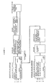
- Figure 1 shows the multi-pulse input signal at the left-hand side and arrows 1 to 4 indicate the multi-pulse input signals from wheels one (left front), two (right front), three (left rear) and four (right rear) on the vehicle.
- These multi-pulse signals are conveniently forty-eight or ninety-six pulses for each revolution of the wheel.
- Figure 1 shows the input stages for the single pulse monitoring system and arrows 5, 6, 7 and 8 show the single pulse per revolution of each wheel inputs.
- the inputs 1 to 4 and 5 to 8 may themselves not be taken directly from the wheels but fed through a first processor.
- the first processor may generate the single pulses for the inputs 5, 6, 7 and 8 from a single input from multi-pulse generators one at each wheel.
- the signals from each wheel are carried through cables to the inputs of the central processing unit and this may be the same computer as is used for the ABS equipment on the vehicle or a separate computer.
- the central processing unit may be the same computer as is used for the ABS equipment on the vehicle or a separate computer.
- Four separate indicator lights are provided one for each wheel and these are most conveniently mounted on the vehicle dashboard.
- the central processing unit monitors the various signals and compares them to determine whether or not it should give an output signal to indicate that any tyre on the vehicle is deflated.
- the single pulse system operates by having a timer running at a fixed frequency of 62.5 kilocycles per second and when the first pulse comes from the first wheel the time is noted. The times of the next fifteen following pulses for the same wheel are also noted giving sixteen times in all. Immediately after the first pulse from the first wheel is received the time of the next pulse from wheel two is noted followed by fifteen further times for that wheel. The same occurs for wheels three and four so that for each wheel sixteen times are recorded against the same clock. Immediately the last wheel to first signal its movement has completed its sixteenth time the calculation of signal begins.
- Interpolation (as shown in box three) is then used to estimate the angular velocity of the four wheels at the same instant chosen to be when the fourth wheel gave its first signal. (This is simply a matter of choice and any instant can be chosen). Thus the angular velocity of all four wheels at the same instant is found by interpolation and these four speeds are passed on to the next stage in the processing unit.
- the processing unit also carries out the multi-pulse system calculation as shown in the top left-hand box in Figure 1.
- the four input 1, 2, 3 and 4 are counted and monitored for a predetermined time period which is typically six seconds although it can be less.
- the processing unit calculates lateral and longitudinal accelerations for the vehicle using the multi-pulse input signals by comparing the angular velocity signals for the wheels on each side of the vehicle and then comparing the signals from the front and rear pair of wheels with the forward speed calculated from the mean of the angular velocity of all four wheels.
- the lateral and longitudinal acceleration figures are compared with predetermined limit values for the vehicle concerned and if these figures are greater then these predetermined figures the system is inhibited and deflation warning calculation is not carried out.
- the determination of the G figures when calculation is inhibited is determined for the particular vehicle concerned and is largely determined by the amount of weight transfer due to these accelerations. Excessive weight transfer causes radius changes in the wheels similar to a puncture and so this effect must be allowed for. Thus false deflation warning signals due to the weight transfer are avoided.
- the processing unit does this for both types of input signal, both multi-pulse and single pulse using the same method for each but in the case of the multi-pulse signal it calculates from counts in the preset time period which in this case is six seconds and in the case of the single pulse system it calculates by using the interpolated wheel speeds and looking at three separate calculation periods which means that it checks over fifteen revolutions of the wheel in this example.
- the system looks for a percentage difference between the diagonal sums greater than .05 and less then .6% and then it knows that there is a deflation on one of the wheels.
- the system then calculates the percentage deviation of the angular velocity of each wheel from the average of the four wheels and this allows it to determine which of the wheels is deflated assuming the percentage difference of the sums of the diagonals has landed in the claimed range.
- the sensing of which particular wheel is deflated is determined by the different signal of one wheel from the average being greater than 0.1%.
- the system uses the same type of calculation for both multi-pulse and single pulse systems and chooses which to signal or sense from according to the speed of the vehicle which is calculated from the average angular velocity.
- the system may choose the best monitoring method to apply at any time and thus is able to maximise the sensitivities and detection times for low and high speeds.
- the system continuously runs both multi- and single-pulse calculations and if both multi-pulse and single pulse systems give indications of a puncture and both indicate the same wheel then the alarm is operated and indicator lights are lit to show that a particular wheel has deflated.
- an initialisation step is built in to the system.
- This comprises a manually- or semi-automatically operated trip which causes the deflation warning system to go through a calibration routine in which it measures the speeds of the four wheels and compares them to calculate the necessary constants for the deflation warning system calculations which are then used subsequently throughout use of the vehicle.
- Initialisation can be at a single speed or may be at two or more speeds according to the types of tyre which may be fitted to the vehicle and their gross properties at high speeds.
Landscapes
- Engineering & Computer Science (AREA)
- Mechanical Engineering (AREA)
- Measuring Fluid Pressure (AREA)
- Indicating Measured Values (AREA)
Applications Claiming Priority (2)
| Application Number | Priority Date | Filing Date | Title |
|---|---|---|---|
| GB909002924A GB9002924D0 (en) | 1990-02-09 | 1990-02-09 | Method of detecting a delfated tyre on a vehicle |
| GB9002924 | 1990-02-09 |
Publications (3)
| Publication Number | Publication Date |
|---|---|
| EP0441599A2 true EP0441599A2 (de) | 1991-08-14 |
| EP0441599A3 EP0441599A3 (en) | 1992-01-08 |
| EP0441599B1 EP0441599B1 (de) | 1994-11-30 |
Family
ID=10670695
Family Applications (1)
| Application Number | Title | Priority Date | Filing Date |
|---|---|---|---|
| EP91300938A Expired - Lifetime EP0441599B1 (de) | 1990-02-09 | 1991-02-05 | Verfahren zum Feststellen eines Druckverlustes in einem Fahrzeugreifen |
Country Status (8)
| Country | Link |
|---|---|
| US (1) | US5239469A (de) |
| EP (1) | EP0441599B1 (de) |
| JP (1) | JP3129454B2 (de) |
| KR (1) | KR960014661B1 (de) |
| DE (1) | DE69105288T2 (de) |
| ES (1) | ES2064897T3 (de) |
| GB (1) | GB9002924D0 (de) |
| TW (1) | TW199130B (de) |
Cited By (9)
| Publication number | Priority date | Publication date | Assignee | Title |
|---|---|---|---|---|
| EP0489563A1 (de) * | 1990-12-06 | 1992-06-10 | Sumitomo Rubber Industries Limited | Verfahren zur Feststellung eines leeren Reifens an einem Fahrzeug |
| EP0489562A1 (de) * | 1990-12-06 | 1992-06-10 | Sumitomo Rubber Industries Limited | Verfahren zur Feststellung eines leeren Reifens an einem Fahrzeug |
| EP0497120A1 (de) * | 1991-01-31 | 1992-08-05 | TEMIC TELEFUNKEN microelectronic GmbH | System zur Luftdruckkontrolle von Kfz-Reifen |
| EP0512745A1 (de) * | 1991-05-02 | 1992-11-11 | Sumitomo Rubber Industries Limited | Verfahren zum Erkennen eines leeren Reifens an einem Fahrzeug |
| DE4327492C1 (de) * | 1993-08-16 | 1995-02-16 | Daimler Benz Ag | Verfahren zur Reifendruckwarnung |
| DE4400913A1 (de) * | 1994-01-14 | 1995-07-20 | Continental Ag | Verfahren und Vorrichtung zur Ermittlung eines Fülldruckverlusts in einem Reifen |
| EP0657313A3 (de) * | 1993-12-07 | 1995-11-29 | Sumitomo Electric Industries | Korrekturverfahren von Ausgangsunterschied von Reifen und Vorrichtung zur Reifendruckabfallserkennung. |
| US5591906A (en) * | 1992-09-16 | 1997-01-07 | Sumitomo Electric Industries, Ltd. | Tire pressure drop detecting device and method |
| WO2001043996A3 (de) * | 1999-12-15 | 2001-12-27 | Continental Ag | Verfahren und vorrichtung zur erkennung eines druckverlustes von reifen in kraftfahrzeugen |
Families Citing this family (29)
| Publication number | Priority date | Publication date | Assignee | Title |
|---|---|---|---|---|
| US5654888A (en) * | 1992-06-20 | 1997-08-05 | Robert Bosch Gmbh | Control arrangement for vehicles |
| US5838230A (en) * | 1992-07-11 | 1998-11-17 | Sumitomo Rubber Industries, Ltd. | Method of detecting a deflated tire on a vehicle |
| JP3032092B2 (ja) * | 1992-12-21 | 2000-04-10 | 住友ゴム工業株式会社 | タイヤの角速度の変化から空気圧異常を検出する装置における自動初期設定方法 |
| FR2701430A1 (fr) * | 1993-02-11 | 1994-08-19 | Michelin & Cie | Procédé d'exploitation des signaux dans un système de surveillance de pneumatiques. |
| JP3270844B2 (ja) * | 1993-02-19 | 2002-04-02 | トヨタ自動車株式会社 | 車両の制御装置 |
| DE4410941A1 (de) * | 1993-03-29 | 1994-10-06 | Mazda Motor | Reifenluftdruckwarnvorrichtung |
| JP3286412B2 (ja) * | 1993-07-27 | 2002-05-27 | マツダ株式会社 | タイヤ空気圧警報装置 |
| GB9320843D0 (en) * | 1993-10-09 | 1993-12-01 | Sumitomo Rubber Ind | Method of detecting a deflated tyre on a vehicle |
| GB9320821D0 (en) * | 1993-10-09 | 1993-12-01 | Sumitomo Rubber Ind | Method of setecting a deflated tyre on a vehicle |
| JPH0891029A (ja) * | 1994-09-27 | 1996-04-09 | Sumitomo Rubber Ind Ltd | タイヤ空気圧低下警報装置 |
| GB9504217D0 (en) * | 1995-03-02 | 1995-04-19 | Sumitomo Rubber Ind | A method of determining the inflation pressure of a tyre on a moving vehicle |
| JP3509331B2 (ja) * | 1995-10-11 | 2004-03-22 | 本田技研工業株式会社 | 車両の車輪減圧判定装置 |
| GB9602442D0 (en) * | 1996-02-07 | 1996-04-03 | Sumitomo Rubber Ind | Method of detecting a deflated tyre on a vehicle |
| GB9602443D0 (en) * | 1996-02-07 | 1996-04-03 | Sumitomo Rubber Ind | Method of detecting a deflated tyre on a vehicle |
| US5844130A (en) | 1996-04-03 | 1998-12-01 | Ssi Technologies | Apparatus for maintaining a constant radial distance between a transmitting circuit and an antenna coil |
| IT1289827B1 (it) * | 1996-11-20 | 1998-10-16 | Fiat Auto Spa | Procedimento ed apparecchiatura per la rilevazione della presenza di un pneumatico almeno parzialmente sgonfio in un autoveicolo |
| US5721528A (en) * | 1996-12-23 | 1998-02-24 | Ford Global Technologies, Inc. | Low tire warning system |
| US6064936A (en) * | 1997-04-14 | 2000-05-16 | Sumitomo Electric Industries, Ltd. | Tire air pressure reduction detecting apparatus |
| US5847645A (en) * | 1997-06-04 | 1998-12-08 | Ford Global Technologies, Inc. | Tire diagnostic system |
| US6118369A (en) * | 1998-08-17 | 2000-09-12 | Ford Motor Company | Tire diagnostic system |
| US6002327A (en) * | 1998-11-04 | 1999-12-14 | Ford Global Technologies, Inc. | Low tire warning system with axle torque signal |
| US6822561B2 (en) * | 1999-12-15 | 2004-11-23 | Continental Aktiengesellschaft | Method and device for detecting a drop in pressure in motor vehicle tires |
| US6222444B1 (en) | 2000-04-03 | 2001-04-24 | Robert Bosch Corporation | Method for detecting a deflated tire on a vehicle |
| US6285280B1 (en) | 2000-06-26 | 2001-09-04 | Robert Bosch Corporation | Method for detecting a deflated tire on a vehicle |
| US6459369B1 (en) | 2000-11-22 | 2002-10-01 | Robert Bosch Corporation | Tire deflation detection system with feedback component |
| US6580980B1 (en) * | 2002-03-05 | 2003-06-17 | Michelin Recherche Et Technique S.A. | System and method for testing deflated tire handling |
| DE602004029642D1 (de) * | 2003-11-25 | 2010-12-02 | Sumitomo Rubber Ind | Verfahren und Gerät zum Detektieren eines Druckabfalls in Reifen, und Programm für die Beurteilung eines Druckabfalls in Reifen |
| KR101320475B1 (ko) * | 2012-02-17 | 2013-10-23 | 주식회사 엠디티 | 차량용 타이어 위치 판독 시스템 |
| US9841905B2 (en) | 2015-12-29 | 2017-12-12 | Pknoa S.A. | File system having a database management system using file pre-allocation in mass storage devices |
Family Cites Families (8)
| Publication number | Priority date | Publication date | Assignee | Title |
|---|---|---|---|---|
| US3613075A (en) * | 1969-10-16 | 1971-10-12 | Eaton Yale & Towne | Tire inflation monitoring system |
| US3691524A (en) * | 1970-06-15 | 1972-09-12 | Eaton Yale & Towne | Tire inflation monitoring system |
| JPS5433772A (en) * | 1977-08-19 | 1979-03-12 | Nippon Denso Co Ltd | Tyre trouble detecting method and system |
| US4224597A (en) * | 1978-10-27 | 1980-09-23 | Avmar, Incorporated | System for detecting underinflated tire in a rolling vehicle |
| US4355298A (en) * | 1979-08-20 | 1982-10-19 | The Bendix Corporation | Low or flat tire warning system |
| JPS5945205A (ja) * | 1982-09-01 | 1984-03-14 | Sumitomo Electric Ind Ltd | 自動車タイヤの空気圧監視装置 |
| FR2568519A1 (fr) * | 1984-08-02 | 1986-02-07 | Michelin & Cie | Dispositif avertisseur de sous-gonflage d'un pneumatique |
| GB8711310D0 (en) * | 1987-05-13 | 1987-06-17 | Sp Tyres Uk Ltd | Tyres deflation warning device |
-
1990
- 1990-02-09 GB GB909002924A patent/GB9002924D0/en active Pending
-
1991
- 1991-01-28 US US07/646,260 patent/US5239469A/en not_active Expired - Lifetime
- 1991-02-01 JP JP03012186A patent/JP3129454B2/ja not_active Expired - Lifetime
- 1991-02-02 TW TW080100858A patent/TW199130B/zh active
- 1991-02-05 ES ES91300938T patent/ES2064897T3/es not_active Expired - Lifetime
- 1991-02-05 EP EP91300938A patent/EP0441599B1/de not_active Expired - Lifetime
- 1991-02-05 DE DE69105288T patent/DE69105288T2/de not_active Expired - Lifetime
- 1991-02-09 KR KR1019910002214A patent/KR960014661B1/ko not_active Expired - Lifetime
Cited By (15)
| Publication number | Priority date | Publication date | Assignee | Title |
|---|---|---|---|---|
| EP0489562A1 (de) * | 1990-12-06 | 1992-06-10 | Sumitomo Rubber Industries Limited | Verfahren zur Feststellung eines leeren Reifens an einem Fahrzeug |
| US5252946A (en) * | 1990-12-06 | 1993-10-12 | Sumitomo Rubber Industries Limited | Method of detecting a deflated tire on a vehicle |
| EP0489563A1 (de) * | 1990-12-06 | 1992-06-10 | Sumitomo Rubber Industries Limited | Verfahren zur Feststellung eines leeren Reifens an einem Fahrzeug |
| EP0497120A1 (de) * | 1991-01-31 | 1992-08-05 | TEMIC TELEFUNKEN microelectronic GmbH | System zur Luftdruckkontrolle von Kfz-Reifen |
| EP0512745A1 (de) * | 1991-05-02 | 1992-11-11 | Sumitomo Rubber Industries Limited | Verfahren zum Erkennen eines leeren Reifens an einem Fahrzeug |
| US5345217A (en) * | 1991-05-02 | 1994-09-06 | Sumitomo Rubber Industries, Ltd. | Method of detecting a deflated tire on a vehicle |
| US5591906A (en) * | 1992-09-16 | 1997-01-07 | Sumitomo Electric Industries, Ltd. | Tire pressure drop detecting device and method |
| DE4327492C1 (de) * | 1993-08-16 | 1995-02-16 | Daimler Benz Ag | Verfahren zur Reifendruckwarnung |
| US5583483A (en) * | 1993-08-16 | 1996-12-10 | Mercedes-Benz Ag | Method for tire pressure warning |
| EP0657313A3 (de) * | 1993-12-07 | 1995-11-29 | Sumitomo Electric Industries | Korrekturverfahren von Ausgangsunterschied von Reifen und Vorrichtung zur Reifendruckabfallserkennung. |
| US5710539A (en) * | 1993-12-07 | 1998-01-20 | Sumitomo Electric Industrties, Ltd. | Tire air-pressure reduction detecting apparatus |
| US5561415A (en) * | 1994-01-14 | 1996-10-01 | Continental Aktiengesellschaft | Method and device for determining filling pressure loss of a pneumatic vehicle tire |
| DE4400913A1 (de) * | 1994-01-14 | 1995-07-20 | Continental Ag | Verfahren und Vorrichtung zur Ermittlung eines Fülldruckverlusts in einem Reifen |
| DE4400913B4 (de) * | 1994-01-14 | 2004-09-09 | Continental Aktiengesellschaft | Verfahren und Vorrichtung zur Ermittlung eines Fülldruckverlusts in einem Reifen |
| WO2001043996A3 (de) * | 1999-12-15 | 2001-12-27 | Continental Ag | Verfahren und vorrichtung zur erkennung eines druckverlustes von reifen in kraftfahrzeugen |
Also Published As
| Publication number | Publication date |
|---|---|
| EP0441599A3 (en) | 1992-01-08 |
| DE69105288T2 (de) | 1995-04-06 |
| DE69105288D1 (de) | 1995-01-12 |
| EP0441599B1 (de) | 1994-11-30 |
| JP3129454B2 (ja) | 2001-01-29 |
| KR910015435A (ko) | 1991-09-30 |
| GB9002924D0 (en) | 1990-04-04 |
| KR960014661B1 (ko) | 1996-10-19 |
| US5239469A (en) | 1993-08-24 |
| JPH04212610A (ja) | 1992-08-04 |
| TW199130B (de) | 1993-02-01 |
| ES2064897T3 (es) | 1995-02-01 |
Similar Documents
| Publication | Publication Date | Title |
|---|---|---|
| US5239469A (en) | Method of detecting a deflated tire on a vehicle | |
| US5192929A (en) | Method of detecting a deflated tire on a vehicle | |
| US5345217A (en) | Method of detecting a deflated tire on a vehicle | |
| US5248957A (en) | Method of detecting a deflated tire on a vehicle | |
| EP0489563B1 (de) | Verfahren zur Feststellung eines leeren Reifens an einem Fahrzeug | |
| EP0291217B2 (de) | Verfahren zur Feststellung eines leeren Reifens auf einem Fahrzeug | |
| US5923244A (en) | Method of detecting a deflated tire on a vehicle | |
| US5541573A (en) | Method of detecting a deflated tire on a vehicle | |
| US6903653B2 (en) | Process and system for determining the onset of tread rubber separations of a pneumatic tire on a vehicle | |
| EP0607690B1 (de) | Verfahren und Vorrichtung zum Erkennen von Reifenfehlern | |
| US5552760A (en) | Method of detecting a deflated tire on a vehicle | |
| US5589816A (en) | Method and device for detecting a deflated tire on a vehicle | |
| US5838230A (en) | Method of detecting a deflated tire on a vehicle |
Legal Events
| Date | Code | Title | Description |
|---|---|---|---|
| PUAI | Public reference made under article 153(3) epc to a published international application that has entered the european phase |
Free format text: ORIGINAL CODE: 0009012 |
|
| AK | Designated contracting states |
Kind code of ref document: A2 Designated state(s): BE DE ES FR GB IT SE |
|
| PUAL | Search report despatched |
Free format text: ORIGINAL CODE: 0009013 |
|
| AK | Designated contracting states |
Kind code of ref document: A3 Designated state(s): BE DE ES FR GB IT SE |
|
| 17P | Request for examination filed |
Effective date: 19920117 |
|
| 17Q | First examination report despatched |
Effective date: 19930831 |
|
| GRAA | (expected) grant |
Free format text: ORIGINAL CODE: 0009210 |
|
| AK | Designated contracting states |
Kind code of ref document: B1 Designated state(s): BE DE ES FR GB IT SE |
|
| ITF | It: translation for a ep patent filed | ||
| REF | Corresponds to: |
Ref document number: 69105288 Country of ref document: DE Date of ref document: 19950112 |
|
| REG | Reference to a national code |
Ref country code: ES Ref legal event code: FG2A Ref document number: 2064897 Country of ref document: ES Kind code of ref document: T3 |
|
| ET | Fr: translation filed | ||
| PLBE | No opposition filed within time limit |
Free format text: ORIGINAL CODE: 0009261 |
|
| STAA | Information on the status of an ep patent application or granted ep patent |
Free format text: STATUS: NO OPPOSITION FILED WITHIN TIME LIMIT |
|
| 26N | No opposition filed | ||
| REG | Reference to a national code |
Ref country code: GB Ref legal event code: IF02 |
|
| PGFP | Annual fee paid to national office [announced via postgrant information from national office to epo] |
Ref country code: ES Payment date: 20100226 Year of fee payment: 20 |
|
| PGFP | Annual fee paid to national office [announced via postgrant information from national office to epo] |
Ref country code: IT Payment date: 20100213 Year of fee payment: 20 Ref country code: FR Payment date: 20100223 Year of fee payment: 20 |
|
| PGFP | Annual fee paid to national office [announced via postgrant information from national office to epo] |
Ref country code: BE Payment date: 20100125 Year of fee payment: 20 Ref country code: GB Payment date: 20100202 Year of fee payment: 20 Ref country code: DE Payment date: 20100211 Year of fee payment: 20 |
|
| PGFP | Annual fee paid to national office [announced via postgrant information from national office to epo] |
Ref country code: SE Payment date: 20100212 Year of fee payment: 20 |
|
| REG | Reference to a national code |
Ref country code: DE Ref legal event code: R071 Ref document number: 69105288 Country of ref document: DE |
|
| BE20 | Be: patent expired |
Owner name: *SUMITOMO RUBBER INDUSTRIES LTD Effective date: 20110205 |
|
| REG | Reference to a national code |
Ref country code: GB Ref legal event code: PE20 Expiry date: 20110204 |
|
| EUG | Se: european patent has lapsed | ||
| PG25 | Lapsed in a contracting state [announced via postgrant information from national office to epo] |
Ref country code: GB Free format text: LAPSE BECAUSE OF EXPIRATION OF PROTECTION Effective date: 20110204 |
|
| REG | Reference to a national code |
Ref country code: ES Ref legal event code: FD2A Effective date: 20120305 |
|
| PG25 | Lapsed in a contracting state [announced via postgrant information from national office to epo] |
Ref country code: ES Free format text: LAPSE BECAUSE OF EXPIRATION OF PROTECTION Effective date: 20110206 |
|
| PG25 | Lapsed in a contracting state [announced via postgrant information from national office to epo] |
Ref country code: DE Free format text: LAPSE BECAUSE OF EXPIRATION OF PROTECTION Effective date: 20110205 |