EP0440575A1 - Method for applying adhesive to a paper web in the tobacco industry and cigarette filter rod obtained by this method - Google Patents
Method for applying adhesive to a paper web in the tobacco industry and cigarette filter rod obtained by this method Download PDFInfo
- Publication number
- EP0440575A1 EP0440575A1 EP91810017A EP91810017A EP0440575A1 EP 0440575 A1 EP0440575 A1 EP 0440575A1 EP 91810017 A EP91810017 A EP 91810017A EP 91810017 A EP91810017 A EP 91810017A EP 0440575 A1 EP0440575 A1 EP 0440575A1
- Authority
- EP
- European Patent Office
- Prior art keywords
- adhesive
- strip
- paper
- glue
- projection device
- Prior art date
- Legal status (The legal status is an assumption and is not a legal conclusion. Google has not performed a legal analysis and makes no representation as to the accuracy of the status listed.)
- Granted
Links
Images


Classifications
-
- A—HUMAN NECESSITIES
- A24—TOBACCO; CIGARS; CIGARETTES; SIMULATED SMOKING DEVICES; SMOKERS' REQUISITES
- A24C—MACHINES FOR MAKING CIGARS OR CIGARETTES
- A24C5/00—Making cigarettes; Making tipping materials for, or attaching filters or mouthpieces to, cigars or cigarettes
- A24C5/14—Machines of the continuous-rod type
- A24C5/24—Pasting the seam
-
- B—PERFORMING OPERATIONS; TRANSPORTING
- B05—SPRAYING OR ATOMISING IN GENERAL; APPLYING FLUENT MATERIALS TO SURFACES, IN GENERAL
- B05B—SPRAYING APPARATUS; ATOMISING APPARATUS; NOZZLES
- B05B7/00—Spraying apparatus for discharge of liquids or other fluent materials from two or more sources, e.g. of liquid and air, of powder and gas
- B05B7/24—Spraying apparatus for discharge of liquids or other fluent materials from two or more sources, e.g. of liquid and air, of powder and gas with means, e.g. a container, for supplying liquid or other fluent material to a discharge device
Definitions
- the subject of the present invention is a method of gluing one or more longitudinal zones of a strip of paper intended to form the envelope of a rod, in particular in the tobacco industry. It also relates to a cigarette filter rod obtained according to the above method.
- the gluing of the paper strips intended to form the cylindrical casing envelopes, in particular in the tobacco industry, is an operation which must satisfy multiple requirements.
- the simplest and most widespread solution up to now consists in using a glue liquid at room temperature, for example polyvinyl acetate, and in gluing the bonding zones which will later form the joints, by transfer of this glue liquid on the paper strip, for example by means of a thin disc driven in rotation of which a part of the periphery is immersed in a container of glue.
- the patent application document DE-34 01 588 describes for example an improvement made to applicators of this kind. Instead of disc applicators, there have also been proposed, for the deposition of polyvinyl acetate glue, glueers provided with a nozzle which opens into contact with the paper (US Pat. No. 3,619,328).
- the aim of the present invention is to propose a simple sizing process making it possible to carry out the sizing operation at high speed on all types of paper, in particular highly porous papers, and the costs of which are used are as small as possible.
- the gluing method according to the invention is characterized in that one or more projection devices are available at a fixed location, the strip is made to pass in front of the device (s). projection at a predetermined distance, different from zero, the projection device (s) is supplied with a glue liquid at room temperature and with compressed air and the projection device (s) is actuated so as to project onto each longitudinal zone to be bonded a jet of fine glue droplets.
- Another object of the invention is therefore a cigarette filter rod obtained according to the method of the invention and characterized in that it comprises a cylindrical envelope formed by a strip of highly porous paper whose edges overlap and are fixed together with a polyvinyl acetate adhesive joint.
- Fig. 1 is a schematic and exploded perspective view showing the displacement of a strip of paper during the formation of a cigarette filter rod
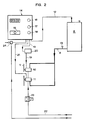
- fig. 2 is a diagram of various components of a sizing installation allowing the sizing of the strip of paper visible in FIG. 1 and
- fig. 3 is an elevational view of an adhesive projector usable in the installation of FIG. 2.
- a strip of paper l which passes at high speed in an installation so as to constitute the envelope of a cigarette filter rod designated by 2.
- the band l constitutes a cylindrical envelope which surrounds a filtering mass 3 of cellulose acetate and the two edges of which are folded over one another and kept fixed by a glue joint 4.
- This glue joint is called the seam joint.
- a second adhesive joint 5 is located in the center of the strip and provides the connection between the filtering mass 3 and the strip l.
- the strip l permanently receives on its central zone 6 a jet of liquid glue forming the internal seal in the form of a median thread.
- a jet of liquid glue forming the internal seal in the form of a median thread.
- a second jet of glue which forms a marginal thread 7 and constitutes the sewing thread.
- the threads 6 and 7 are approximately 2 mm wide.
- the strip 1 After having received the glue threads 6 and 7, projected horizontally, the strip 1 is led into a device for forming the tube, which is known per se and is only shown diagrammatically in FIG. l.
- Guide means raise the edges of the strip to give it the shape of a U in which a continuous bar 3 of cellulose acetate, forming the filter material is engaged.
- the assembly of the strip l and of the filling 3 then passes through a closing guide 27 in which the two edges of the strip l are folded over the mass 3 and pressed against each other, thus ensuring the adhesion of the connecting zones 6 and 7.
- the sausage is then dried and cut into segments which are incorporated into cigarettes during subsequent operations.
- the means used to deposit the two adhesive threads 6 and 7 are shown in more detail in FIGS. 2 and 3.
- Fig. 2 shows the entire planned installation.
- This installation includes a fully closed glue tank 8.
- Tubing 9 comes out and leads the liquid adhesive to the two projectors 10 and 11 which are placed in front of the strip l at locations fixed so as to project the adhesive joints 6 and 7 thereon.
- a tube 12 compressed air is admitted into the upper part of the container 8 in order to pressurize the liquid adhesive contained in this reservoir.
- a valve 13 and a connector on the pipe 9 make it possible to supply the container 8 with adhesive, if necessary.
- the installation requires a supply of compressed air and adjustment and control means acting on this supply.
- the control panel 14 comprises, in addition to the control switch 15, regulators 16, 17 and 18 adjustable and consequently making it possible to adjust the air pressures going, on the one hand, to the container 8 by the tube 12, d on the other hand, to the projector 10 by a pipe 19 into which a heating device 20 is introduced and finally into a conduit 21 which supplies the projector 11.
- the projection devices 10 and 11 are also supplied with compressed air at unregulated pressure, from a pipe 22, through a control valve 23. This command makes it possible to maneuver the needle of the projectors, as will be seen below.
- the general supply of table 14 is carried out from a source of compressed air through a presetting regulator 24.
- the device 10 comprises a nozzle 25 provided with an opening calibrated at its front end.
- a movable needle, visible at 26, is biased by a spring so as to be held in a position where it closes the opening of the nozzle.
- the air pressure arriving through the conduit 22 causes the needle to retreat and consequently the opening of the nozzle.
- a mixture of air and liquid coming from the two conduits 9 and 19 is then brought behind the opening of the nozzle and projects a jet of fine droplets of liquid on the strip l which passes at high speed in front of this nozzle, at a certain distance, for example of the order of 4 mm. It has been found that different features make it possible to obtain results which fully satisfy the conditions.
- the dosage of the adhesive with regard to the degree of fluidity and its capillarity characteristics must be adjusted by means of preliminary tests as a function of the desired running speed and the type of paper to be bonded.
- the compressed air pressures must be determined from case to case with accuracy, as mentioned above.
- the diameter of the droplets and the spraying rate depend on the characteristics of the nozzle opening as well as the dimensions and the shape of the interior chamber in which the mixing takes place. .
Abstract
Description
La présente invention a pour objet un procédé d'encollage d'une ou plusieurs zones longitudinales d'une bande de papier destinée à former l'enveloppe d'un boudin, notamment dans l'industrie du tabac. Elle a également pour objet un boudin de filtre à cigarette obtenu selon le procédé précité.The subject of the present invention is a method of gluing one or more longitudinal zones of a strip of paper intended to form the envelope of a rod, in particular in the tobacco industry. It also relates to a cigarette filter rod obtained according to the above method.
L'encollage des bandes de papier destinées à former les enveloppes cylindriques de boudin, notamment dans l'industrie du tabac, est une opération qui doit satisfaire à de multiples exigences. La solution la plus simple et la plus répandue jusqu'à maintenant, consiste à utiliser une colle liquide à la température ambiante, par exemple le polyvinyle-acétate, et à encoller les zones de liaison qui formeront ultérieurement les joints, par transfert de cette colle liquide sur la bande de papier, par exemple au moyen d'un disque mince entraîné en rotation dont une partie de la périphérie plonge dans un récipient de colle. Le document de demande de brevet DE-34 01 588 décrit par exemple un perfectionnement apporté aux applicateurs de ce genre. Au lieu des applicateurs à disques, on a également proposé, pour le dépôt de colle de polyvinyle-acétate, des encolleurs munis d'une buse qui débouche au contact du papier (US-3,619,328).The gluing of the paper strips intended to form the cylindrical casing envelopes, in particular in the tobacco industry, is an operation which must satisfy multiple requirements. The simplest and most widespread solution up to now consists in using a glue liquid at room temperature, for example polyvinyl acetate, and in gluing the bonding zones which will later form the joints, by transfer of this glue liquid on the paper strip, for example by means of a thin disc driven in rotation of which a part of the periphery is immersed in a container of glue. The patent application document DE-34 01 588 describes for example an improvement made to applicators of this kind. Instead of disc applicators, there have also been proposed, for the deposition of polyvinyl acetate glue, glueers provided with a nozzle which opens into contact with the paper (US Pat. No. 3,619,328).
Toutefois, un inconvénient majeur de ces dispositifs est qu'ils sont inutilisables avec les papiers hautement poreux dont l'utilisation se répand de plus en plus, notamment dans la fabrication des boudins de filtre. Ces dispositifs ont par ailleurs d'autres inconvénients notamment la vitesse d'application est limitée.However, a major drawback of these devices is that they cannot be used with highly porous papers, the use of which is becoming more and more widespread, in particular in the manufacture of filter tubes. These devices also have other drawbacks, in particular the speed of application is limited.
On a proposé plus récemment d'utiliser, pour l'opération d'encollage, des colles à haute température de fusion, qui se solidifient à la température ambiante et qui doivent par conséquent être appliquées à chaud. On peut, pour cela utiliser des dispositifs qui projettent la colle liquide sur la bande de papier et le brevet allemand DE-35 25 889 par exemple, décrit la construction d'une buse de projection adaptée à cette technique. Celle-ci est avantageuse dans certains cas, notamment lorsque les exigences en ce qui concerne la résistance du joint de colle sont élevées, mais elle est d'une application délicate. Le procédé est coûteux. La vitesse d'application est également relativement limitée. Enfin, l'utilisation de colle liquide à chaud ne convient pas pour les papiers hautement poreux dont on a parlé plus haut.More recently, it has been proposed to use, for the sizing operation, adhesives with a high melting temperature, which solidify at ambient temperature and which must therefore be applied hot. For this, it is possible to use devices which project the liquid glue onto the paper strip and the German patent DE-35 25 889 for example, describes the construction of a spray nozzle adapted to this technique. This is advantageous in certain cases, especially when the requirements with regard to the strength of the adhesive joint are high, but it is difficult to apply. The process is expensive. The application speed is also relatively limited. Finally, the use of hot liquid glue is not suitable for the highly porous papers mentioned above.
L'emploi d'applicateurs à pulvérisateurs est également connu pour le dépôt d'adhésifs dits "structuraux" ou des colles de polychloroprène et acryliques (FR-26 23 108). Le contenu de ce dernier document ne permet toutefois pas d'arriver à une solution fiable au problème de l'encollage des enveloppes des boudins dans l'industrie du tabac, tel qu'il se présente actuellement.The use of spray applicators is also known for depositing so-called "structural" adhesives or polychloroprene and acrylic adhesives (FR-26 23 108). The content of this latter document does not, however, allow a reliable solution to be found to the problem of the sizing of the casing envelopes in the tobacco industry, as it currently stands.
Ainsi, le but de la présente invention est de proposer un procédé d'encollage simple permettant de réaliser l'opération d'encollage à grande vitesse sur tous les genres de papier, notamment les papiers hautement poreux, et dont les coûts de mise en oeuvre soient aussi réduits que possible.Thus, the aim of the present invention is to propose a simple sizing process making it possible to carry out the sizing operation at high speed on all types of paper, in particular highly porous papers, and the costs of which are used are as small as possible.
Dans ce but, le procédé d'encollage selon l'invention, du genre mentionné au début, est caractérisé en ce qu'on dispose un ou plusieurs dispositifs de projection à un emplacement fixe, on fait défiler la bande devant le ou les dispositifs de projection à une distance prédéterminée, différente de zéro, on alimente le ou les dispositifs de projection avec une colle liquide à la température ambiante et avec de l'air comprimé et on actionne le ou les dispositifs de projection de manière à projeter sur chaque zone longitudinale à encoller un jet de fines gouttelettes de colle.For this purpose, the gluing method according to the invention, of the kind mentioned at the start, is characterized in that one or more projection devices are available at a fixed location, the strip is made to pass in front of the device (s). projection at a predetermined distance, different from zero, the projection device (s) is supplied with a glue liquid at room temperature and with compressed air and the projection device (s) is actuated so as to project onto each longitudinal zone to be bonded a jet of fine glue droplets.
Une application particulièrement avantageuse de ce procédé concerne la fabrication des boudins de filtre à cigarette. Un autre objet de l'invention est donc un boudin de filtre à cigarette obtenu selon le procédé de l'invention et caractérisé en ce qu'il comporte une enveloppe cylindrique formée d'une bande de papier hautement poreux dont les bords se recouvrent et sont fixés ensemble par un joint de colle de polyvinyle-acétate.A particularly advantageous application of this method relates to the manufacture of cigarette filter tubes. Another object of the invention is therefore a cigarette filter rod obtained according to the method of the invention and characterized in that it comprises a cylindrical envelope formed by a strip of highly porous paper whose edges overlap and are fixed together with a polyvinyl acetate adhesive joint.
On va décrire ci-après, à titre d'exemple et en se référant au dessin annexé, une forme de mise en oeuvre du procédé selon l'invention.We will describe below, by way of example and with reference to the accompanying drawing, a form of implementation of the method according to the invention.
La fig. 1 est une vue en perspective schématique et éclatée montrant le déplacement d'une bande de papier au cours de la formation d'un boudin de filtre à cigarette,Fig. 1 is a schematic and exploded perspective view showing the displacement of a strip of paper during the formation of a cigarette filter rod,
la fig. 2 est un schéma de divers composants d'une installation d'encollage permettant l'encollage de la bande de papier visible à la fig. 1 etfig. 2 is a diagram of various components of a sizing installation allowing the sizing of the strip of paper visible in FIG. 1 and
la fig. 3 est une vue en élévation d'un projecteur de colle utilisable dans l'installation de la fig. 2.fig. 3 is an elevational view of an adhesive projector usable in the installation of FIG. 2.
A la fig. l, on voit une bande de papier l qui défile à grande vitesse dans une installation de manière à constituer l'enveloppe d'un boudin de filtre de cigarette désigné par 2. Lorsque le boudin est formé, la bande l constitue une enveloppe cylindrique qui entoure une masse filtrante 3 d'acétate de cellulose et dont les deux bords sont rabattus l'un sur l'autre et maintenus fixés par un joint de colle 4. Ce joint de colle est appelé le joint de couture. Un second joint de colle 5 est situé au centre de la bande et assure la liaison entre la masse filtrante 3 et la bande l.In fig. l, we see a strip of paper l which passes at high speed in an installation so as to constitute the envelope of a cigarette filter rod designated by 2. When the rod is formed, the band l constitutes a cylindrical envelope which surrounds a filtering
Pour permettre un encollage à grande vitesse, la bande l reçoit en permanence sur sa zone centrale 6 un jet de colle liquide formant le joint intérieur sous forme d'un filet médian. D'autre part, le long d'un de ses bords, elle reçoit un second jet de colle qui forme un filet marginal 7 et constitue le filet de couture. Les filets 6 et 7 ont une largeur d'environ 2 mm.To allow gluing at high speed, the strip l permanently receives on its central zone 6 a jet of liquid glue forming the internal seal in the form of a median thread. On the other hand, along one of its edges, it receives a second jet of glue which forms a
Après avoir reçu les filets de colle 6 et 7, projetés horizontalement, la bande l est conduite dans un dispositif de formation du boudin, qui est connu en soi et n'est représenté que schématiquement à la fig. l. Des moyens de guidage relèvent les bords de la bande pour lui donner la forme d'un U dans lequel une barre continue 3 d'acétate de cellulose, formant la matière du filtre est engagée. L'ensemble de la bande l et du remplissage 3 passe ensuite dans un guide de fermeture 27 dans lequel les deux bords de la bande l sont rabattus sur la masse 3 et pressés l'un contre l'autre, assurant ainsi l'adhérence des zones de liaison 6 et 7.After having received the
Le boudin est ensuite séché puis découpé en segments qui sont incorporés aux cigarettes au cours d'opérations ultérieures.The sausage is then dried and cut into segments which are incorporated into cigarettes during subsequent operations.
Les moyens utilisés pour déposer les deux filets de colle 6 et 7 sont représentés plus en détail aux fig. 2 et 3.The means used to deposit the two
La fig. 2 montre l'ensemble de l'installation prévue. Cette installation comporte un réservoir de colle 8 entièrement fermé. Une tubulure 9 en sort et conduit la colle liquide aux deux projecteurs 10 et 11 qui sont placés devant la bande l à des emplacements fixes de façon à projeter sur elle les joints de colle 6 et 7. Par une tubulure 12, de l'air comprimé est admis dans la partie supérieure du récipient 8 afin de mettre en pression la colle liquide contenue dans ce réservoir. Une vanne 13 et un raccord sur la conduite 9 permettent de procéder à l'alimentation du récipient 8 en colle, en cas de besoin.Fig. 2 shows the entire planned installation. This installation includes a fully closed
L'installation nécessite une alimentation en air comprimé et des moyens de réglage et de commande agissant sur cette alimentation. Le tableau de commande 14 comporte, outre le commutateur de commande 15, des détendeurs 16, 17 et 18 ajustables et permettant par conséquent de régler les pressions de l'air allant, d'une part, au récipient 8 par la tubulure 12, d'autre part, au projecteur 10 par une canalisation 19 dans laquelle est introduit un dispositif de réchauffage 20 et enfin dans un conduit 21 qui alimente le projecteur 11. Les dispositifs de projection 10 et 11 sont également alimentés en air comprimé à pression non réglée, à partir d'une canalisation 22, à travers une vanne de commande 23. Cette commande permet de manoeuvrer le pointeau des projecteurs, comme on le verra plus loin. L'alimentation générale du tableau 14 s'effectue à partir d'une source d'air comprimé à travers un détendeur à pré-réglage 24.The installation requires a supply of compressed air and adjustment and control means acting on this supply. The
On a constaté que l'on pouvait obtenir une installation fonctionnant parfaitement et répondant aux exigences les plus sévères en utilisant des dispositifs de projection de construction très simple et courante comme le dispositif 10 représenté à la fig. 3. Ce dispositif comprend trois raccords d'entrée situés à sa partie arrière et qui sont raccordés respectivement aux conduits 9, 19 et 22. Dans le cas du dispositif 11, la tubulure d'amenée d'air de pulvérisation sera la tubulure 21 et non pas la tubulure 19.It has been found that an installation which functions perfectly and meets the most severe requirements can be obtained by using projection devices of very simple and common construction such as the
Le dispositif 10 comporte une buse 25 munie d'une ouverture calibrée à son extrémité antérieure. Un pointeau mobile, visible en 26, est sollicité par un ressort de façon à être maintenu dans une position où il obture l'ouverture de la buse. La pression d'air arrivant par le conduit 22 provoque le recul du pointeau et par conséquent l'ouverture de la buse. Un mélange d'air et de liquide provenant des deux conduits 9 et 19 est alors amené derrière l'ouverture de la buse et projette un jet de fines gouttelettes de liquide sur la bande l qui défile à grande vitesse devant cette buse, à une certaine distance, par exemple de l'ordre de 4 mm. On a constaté que différentes particularités permettaient d'obtenir des résultats qui satisfont pleinement aux conditions.The
Ainsi, il est avantageux de préchauffer l'air de projection du mélange destiné à former le joint de couture 7.Thus, it is advantageous to preheat the air for spraying the mixture intended to form the
De toute manière, le dosage de la colle en ce qui concerne le degré de fluidité et ses caractéristiques de capillarité doit être ajusté au moyen d'essais préalables en fonction de la vitesse de défilement désirée et du type de papier à encoller. De même, les pressions d'air comprimé doivent être déterminées de cas en cas avec exactitude, comme on l'a dit plus haut.In any case, the dosage of the adhesive with regard to the degree of fluidity and its capillarity characteristics must be adjusted by means of preliminary tests as a function of the desired running speed and the type of paper to be bonded. Likewise, the compressed air pressures must be determined from case to case with accuracy, as mentioned above.
Comme dans tout dispositif de projection sous flux d'air comprimé, le diamètre des gouttelettes et le débit de projection dépendent des caractéristiques de l'ouverture de la buse ainsi que des dimensions et de la forme de la chambre intérieure dans laquelle se fait le mélange.As in any spraying device under compressed air flow, the diameter of the droplets and the spraying rate depend on the characteristics of the nozzle opening as well as the dimensions and the shape of the interior chamber in which the mixing takes place. .
On a constaté que le dispositif de projection décrit, qui est extrêmement simple, permet de réaliser un encollage fiable même sur des papiers hautement poreux à des vitesses encore inatteignables jusqu'à maintenant, par exemple des vitesses de l'ordre de 400 m/min.It has been found that the projection device described, which is extremely simple, makes it possible to carry out a reliable sizing even on highly porous papers at speeds which are still unattainable up to now, for example, speeds of the order of 400 m / min.
Des essais ont même montré qu'il était possible d'envisager une augmentation des vitesses de défilement jusqu'à un ordre de 600 m/min.Tests have even shown that it is possible to envisage an increase in running speeds up to an order of 600 m / min.
La colle qui se dépose par projection, en très fines gouttelettes, sur les fibres du papier ne pénètre pas dans l'épaisseur de ce dernier. On obtient ainsi, notamment au joint dit "de couture" une liaison fiable, évitant tout encrassement des machines, même avec un papier hautement poreux.The glue which is deposited by projection, in very fine droplets, on the paper fibers does not penetrate the thickness of the latter. A reliable connection is thus obtained, in particular at the so-called "sewing" joint, preventing any fouling of the machines, even with highly porous paper.
Claims (9)
Applications Claiming Priority (2)
| Application Number | Priority Date | Filing Date | Title |
|---|---|---|---|
| CH315/90 | 1990-01-31 | ||
| CH31590 | 1990-01-31 |
Publications (2)
| Publication Number | Publication Date |
|---|---|
| EP0440575A1 true EP0440575A1 (en) | 1991-08-07 |
| EP0440575B1 EP0440575B1 (en) | 1994-09-21 |
Family
ID=4184209
Family Applications (1)
| Application Number | Title | Priority Date | Filing Date |
|---|---|---|---|
| EP19910810017 Expired - Lifetime EP0440575B1 (en) | 1990-01-31 | 1991-01-11 | Method for applying adhesive to a paper web in the tobacco industry and cigarette filter rod obtained by this method |
Country Status (2)
| Country | Link |
|---|---|
| EP (1) | EP0440575B1 (en) |
| DE (1) | DE69104078T2 (en) |
Cited By (2)
| Publication number | Priority date | Publication date | Assignee | Title |
|---|---|---|---|---|
| EP1889890A1 (en) | 2006-08-08 | 2008-02-20 | Celanese Emulsions GmbH | Method for applying a polyvinyl ester dispersion adhesive using a jet and use of polyvinyl ester dispersion adhesives |
| EP2865455A3 (en) * | 2013-10-28 | 2015-06-24 | International Tobacco Machinery Poland Sp. z o.o. | Fluid feeding method and nozzle |
Families Citing this family (1)
| Publication number | Priority date | Publication date | Assignee | Title |
|---|---|---|---|---|
| EP1442665B1 (en) | 2003-01-31 | 2006-06-21 | Hauni Maschinenbau AG | Method for applying adhesive to a moving web, as well as device, particularly to perform the method |
Citations (10)
| Publication number | Priority date | Publication date | Assignee | Title |
|---|---|---|---|---|
| US3619328A (en) * | 1967-07-17 | 1971-11-09 | Molins Machine Co Ltd | Apparatus for applying adhesive to continuous webs |
| FR2120842A5 (en) * | 1970-12-30 | 1972-08-18 | Hauni Werke Koerber & Co Kg | |
| GB1305023A (en) * | 1969-06-03 | 1973-01-31 | ||
| FR2290167A1 (en) * | 1974-11-07 | 1976-06-04 | Hauni Werke Koerber & Co Kg | MACHINE FOR THE MANUFACTURE OF A FILTERING MATERIAL BLOCK FROM STICKS OF FILTERING MATERIAL COMPOSED OF DIFFERENT CONSTITUENTS |
| FR2374214A1 (en) * | 1976-12-15 | 1978-07-13 | Acumeter Lab | PROCESS AND MACHINE FOR WRAPPING CYLINDRICAL RELATED ELEMENTS IN A SHEET |
| FR2421682A1 (en) * | 1978-04-06 | 1979-11-02 | Cir Spa Divisione Sasib | APPARATUS FOR SUPPLYING LIQUID ADHESIVE TO A NOZZLE APPLICATOR |
| GB2029280A (en) * | 1978-05-31 | 1980-03-19 | Britannia Refining Co Ltd | Glue dispensing apparatus for a labelling machine. |
| GB2053740A (en) * | 1979-08-27 | 1981-02-11 | Acumeter Lab | Adhesive applicator |
| DE8803131U1 (en) * | 1988-03-08 | 1988-04-21 | Claassen, Henning J., 2120 Lueneburg, De | |
| FR2623108A1 (en) * | 1987-11-12 | 1989-05-19 | Tm Tiziana Mazza | APPARATUS FOR APPLYING ADHESIVE FILMS USING A SPRAY GUN |
-
1991
- 1991-01-11 DE DE1991604078 patent/DE69104078T2/en not_active Expired - Fee Related
- 1991-01-11 EP EP19910810017 patent/EP0440575B1/en not_active Expired - Lifetime
Patent Citations (10)
| Publication number | Priority date | Publication date | Assignee | Title |
|---|---|---|---|---|
| US3619328A (en) * | 1967-07-17 | 1971-11-09 | Molins Machine Co Ltd | Apparatus for applying adhesive to continuous webs |
| GB1305023A (en) * | 1969-06-03 | 1973-01-31 | ||
| FR2120842A5 (en) * | 1970-12-30 | 1972-08-18 | Hauni Werke Koerber & Co Kg | |
| FR2290167A1 (en) * | 1974-11-07 | 1976-06-04 | Hauni Werke Koerber & Co Kg | MACHINE FOR THE MANUFACTURE OF A FILTERING MATERIAL BLOCK FROM STICKS OF FILTERING MATERIAL COMPOSED OF DIFFERENT CONSTITUENTS |
| FR2374214A1 (en) * | 1976-12-15 | 1978-07-13 | Acumeter Lab | PROCESS AND MACHINE FOR WRAPPING CYLINDRICAL RELATED ELEMENTS IN A SHEET |
| FR2421682A1 (en) * | 1978-04-06 | 1979-11-02 | Cir Spa Divisione Sasib | APPARATUS FOR SUPPLYING LIQUID ADHESIVE TO A NOZZLE APPLICATOR |
| GB2029280A (en) * | 1978-05-31 | 1980-03-19 | Britannia Refining Co Ltd | Glue dispensing apparatus for a labelling machine. |
| GB2053740A (en) * | 1979-08-27 | 1981-02-11 | Acumeter Lab | Adhesive applicator |
| FR2623108A1 (en) * | 1987-11-12 | 1989-05-19 | Tm Tiziana Mazza | APPARATUS FOR APPLYING ADHESIVE FILMS USING A SPRAY GUN |
| DE8803131U1 (en) * | 1988-03-08 | 1988-04-21 | Claassen, Henning J., 2120 Lueneburg, De |
Cited By (2)
| Publication number | Priority date | Publication date | Assignee | Title |
|---|---|---|---|---|
| EP1889890A1 (en) | 2006-08-08 | 2008-02-20 | Celanese Emulsions GmbH | Method for applying a polyvinyl ester dispersion adhesive using a jet and use of polyvinyl ester dispersion adhesives |
| EP2865455A3 (en) * | 2013-10-28 | 2015-06-24 | International Tobacco Machinery Poland Sp. z o.o. | Fluid feeding method and nozzle |
Also Published As
| Publication number | Publication date |
|---|---|
| DE69104078T2 (en) | 1995-04-20 |
| EP0440575B1 (en) | 1994-09-21 |
| DE69104078D1 (en) | 1994-10-27 |
Similar Documents
| Publication | Publication Date | Title |
|---|---|---|
| US7140164B2 (en) | Method of and apparatus for applying adhesive to running webs of paper and the like | |
| JP5049697B2 (en) | Paper glue for continuous production | |
| CH667375A5 (en) | ELEMENT FOR FILTERING TOBACCO SMOKE AND SMOKING ARTICLE COMPRISING SUCH AN ELEMENT. | |
| CH640155A5 (en) | CARTRIDGE CONTAINING SPRAY MATERIAL AND SPRAYING APPARATUS. | |
| CH649901A5 (en) | PROCESS AND MACHINE FOR THE MANUFACTURE OF A ROD OF COMPOSITE FILTERS, ESPECIALLY FOR CIGARETTES. | |
| EP0440575B1 (en) | Method for applying adhesive to a paper web in the tobacco industry and cigarette filter rod obtained by this method | |
| US3320110A (en) | Apparatus for making filament tobacco smoke filters | |
| IL26609A (en) | Bonded fibrous materials and process and apparatus for their manufacture | |
| EP1107832A1 (en) | Nozzle | |
| US4036114A (en) | Apparatus for cigarette filter manufacture | |
| US3619328A (en) | Apparatus for applying adhesive to continuous webs | |
| EP0558447A1 (en) | Method and apparatus for the injection of a product in a tobacco rod | |
| US7470448B2 (en) | System and method for applying glue to a moving web | |
| JPH04229164A (en) | Filling apparatus for tobacco, specially for cut tobacco | |
| US5229166A (en) | Cigarette filter rod and method of making same | |
| FR2485441A1 (en) | INTEGRATED FEED DEVICE OF STYLOGRAPHIC USTENSILE OF AN AUTOMATIC OR SIMILAR STYLOGRAPHIC MACHINE | |
| US2113244A (en) | Adhesive spraying attachment | |
| FR2537405A1 (en) | PROCESS FOR THE MANUFACTURE OF FIBER STICKS PROVIDED FOR USE AS CIGARETTE FILTERS | |
| EP0577539B1 (en) | Device for coating and/or impregnating a continuously moving web with a liquid or a pasty fluid | |
| US2012396A (en) | Device for discharging pasty, viscous or liquid substances | |
| US3525343A (en) | Apparatus for producing non-filter cigarettes | |
| US642656A (en) | Apparatus for making paper tubes. | |
| FR2541434A1 (en) | INSTANTANEOUS GAS WATER HEATER | |
| CA2189966A1 (en) | Improved lighter producing a tinted flame, tinting composition therefor and refill member | |
| FR2604687A1 (en) | METHOD AND MACHINE FOR ENCHAPPING PARTICULARLY EXPLOSIVE EXPLOSIVES |
Legal Events
| Date | Code | Title | Description |
|---|---|---|---|
| PUAI | Public reference made under article 153(3) epc to a published international application that has entered the european phase |
Free format text: ORIGINAL CODE: 0009012 |
|
| AK | Designated contracting states |
Kind code of ref document: A1 Designated state(s): CH DE GB IT LI |
|
| 17P | Request for examination filed |
Effective date: 19911023 |
|
| 17Q | First examination report despatched |
Effective date: 19921023 |
|
| GRAA | (expected) grant |
Free format text: ORIGINAL CODE: 0009210 |
|
| AK | Designated contracting states |
Kind code of ref document: B1 Designated state(s): CH DE GB IT LI |
|
| REF | Corresponds to: |
Ref document number: 69104078 Country of ref document: DE Date of ref document: 19941027 |
|
| ITF | It: translation for a ep patent filed |
Owner name: STUDIO TORTA SOCIETA' SEMPLICE |
|
| GBT | Gb: translation of ep patent filed (gb section 77(6)(a)/1977) |
Effective date: 19941201 |
|
| PLBE | No opposition filed within time limit |
Free format text: ORIGINAL CODE: 0009261 |
|
| STAA | Information on the status of an ep patent application or granted ep patent |
Free format text: STATUS: NO OPPOSITION FILED WITHIN TIME LIMIT |
|
| 26N | No opposition filed | ||
| PGFP | Annual fee paid to national office [announced via postgrant information from national office to epo] |
Ref country code: CH Payment date: 19991220 Year of fee payment: 10 |
|
| PGFP | Annual fee paid to national office [announced via postgrant information from national office to epo] |
Ref country code: DE Payment date: 19991227 Year of fee payment: 10 |
|
| PG25 | Lapsed in a contracting state [announced via postgrant information from national office to epo] |
Ref country code: LI Free format text: LAPSE BECAUSE OF NON-PAYMENT OF DUE FEES Effective date: 20010131 Ref country code: CH Free format text: LAPSE BECAUSE OF NON-PAYMENT OF DUE FEES Effective date: 20010131 |
|
| PGFP | Annual fee paid to national office [announced via postgrant information from national office to epo] |
Ref country code: GB Payment date: 20010606 Year of fee payment: 11 |
|
| REG | Reference to a national code |
Ref country code: CH Ref legal event code: PL |
|
| PG25 | Lapsed in a contracting state [announced via postgrant information from national office to epo] |
Ref country code: DE Free format text: LAPSE BECAUSE OF NON-PAYMENT OF DUE FEES Effective date: 20011101 |
|
| REG | Reference to a national code |
Ref country code: GB Ref legal event code: IF02 |
|
| PG25 | Lapsed in a contracting state [announced via postgrant information from national office to epo] |
Ref country code: GB Free format text: LAPSE BECAUSE OF NON-PAYMENT OF DUE FEES Effective date: 20020111 |
|
| GBPC | Gb: european patent ceased through non-payment of renewal fee |
Effective date: 20020111 |
|
| PG25 | Lapsed in a contracting state [announced via postgrant information from national office to epo] |
Ref country code: IT Free format text: LAPSE BECAUSE OF NON-PAYMENT OF DUE FEES;WARNING: LAPSES OF ITALIAN PATENTS WITH EFFECTIVE DATE BEFORE 2007 MAY HAVE OCCURRED AT ANY TIME BEFORE 2007. THE CORRECT EFFECTIVE DATE MAY BE DIFFERENT FROM THE ONE RECORDED. Effective date: 20050111 |