EP0440242A2 - Schaltung zur Rauschverminderung für Videosignalaufzeichnungs- und -wiedergabegerät - Google Patents
Schaltung zur Rauschverminderung für Videosignalaufzeichnungs- und -wiedergabegerät Download PDFInfo
- Publication number
- EP0440242A2 EP0440242A2 EP91101311A EP91101311A EP0440242A2 EP 0440242 A2 EP0440242 A2 EP 0440242A2 EP 91101311 A EP91101311 A EP 91101311A EP 91101311 A EP91101311 A EP 91101311A EP 0440242 A2 EP0440242 A2 EP 0440242A2
- Authority
- EP
- European Patent Office
- Prior art keywords
- noise reduction
- subtracting
- output
- video signal
- reduction circuit
- Prior art date
- Legal status (The legal status is an assumption and is not a legal conclusion. Google has not performed a legal analysis and makes no representation as to the accuracy of the status listed.)
- Granted
Links
Images


Classifications
-
- H—ELECTRICITY
- H04—ELECTRIC COMMUNICATION TECHNIQUE
- H04N—PICTORIAL COMMUNICATION, e.g. TELEVISION
- H04N5/00—Details of television systems
- H04N5/76—Television signal recording
- H04N5/91—Television signal processing therefor
- H04N5/92—Transformation of the television signal for recording, e.g. modulation, frequency changing; Inverse transformation for playback
-
- H—ELECTRICITY
- H04—ELECTRIC COMMUNICATION TECHNIQUE
- H04N—PICTORIAL COMMUNICATION, e.g. TELEVISION
- H04N5/00—Details of television systems
- H04N5/76—Television signal recording
- H04N5/91—Television signal processing therefor
- H04N5/911—Television signal processing therefor for the suppression of noise
-
- H—ELECTRICITY
- H04—ELECTRIC COMMUNICATION TECHNIQUE
- H04N—PICTORIAL COMMUNICATION, e.g. TELEVISION
- H04N5/00—Details of television systems
- H04N5/76—Television signal recording
- H04N5/91—Television signal processing therefor
- H04N5/92—Transformation of the television signal for recording, e.g. modulation, frequency changing; Inverse transformation for playback
- H04N5/923—Transformation of the television signal for recording, e.g. modulation, frequency changing; Inverse transformation for playback using preemphasis of the signal before modulation and deemphasis of the signal after demodulation
Definitions
- the present invention relates to noise reduction circuits, and more particularly, to a noise reduction circuit for reducing noise included in a reproduced video signal from a video signal recording/reproduction device such as a video tape recorder (referred to as a VTR hereinafter).
- a video signal recording/reproduction device such as a video tape recorder
- Video signal recording/reproduction devices such as VTRs are usually provided with noise reduction circuits for reducing noise within reproduced video signals generated at the time of recording video signals onto a recording medium such as a magnetic tape and/or reproducing video signals therefrom.
- a video signal comprises a luminance signal (Y signal) and a chrominance signal (C signal) interleaved with each other at the interval of 1/2 ⁇ f H .
- Y signal luminance signal
- C signal chrominance signal
- Fig. 1 is a block diagram schematically showing a non-recursive type noise reduction circuit which is an example of such conventional noise reduction circuits for reducing noise components.
- the delay line is not limited to 1 delay line, and may be any nH (n: natural number) delay line.
- the reproduced luminance signal delayed by 1H period in 1H delay line 2 is applied to a negative input terminal of a subtractor 3.
- the current reproduced luminance signal provided to input terminal 1 is applied to a positive input terminal of subtractor 3, as well as to a positive input terminal of a subtractor 6.
- Subtractor 3 subtracts the reproduced luminance signal 1H-delayed by 1H delay line 2 from the current reproduced luminance signal which is provided from input terminal 1. Because the video information of the reproduced luminance signals having 1H period interval are in close approximity, i.e. have line correlation, noise components not related to video information (no line correlation) are extracted from subtractor 3.
- the extracted noise component has the amplitude thereof limited via a limiter 4 to be applied to an attenuator 5 where its level is attenuated.
- the noise component is then applied to a negative input terminal of subtractor 6.
- the positive input terminal of subtractor 6 is supplied with the current reproduced luminance signal from input terminal 1.
- Subtractor 6 subtracts the noise component from the current reproduced luminance signal.
- a reproduced luminance signal having the noise component reduced is provided via an output terminal 7.
- a VTR has been proposed performing de-emphasis in the vertical direction and noise reduction simultaneously, where the level of a signal component not having line correlation is emphasized, i.e., vertical emphasis is applied to a luminance signal to record a video signal on a magnetic tape, and the reproduced luminance signal is passed through a recursive type noise reduction circuit at the time of reproduction.
- a recursive type noise reduction circuit employed in such VTRs is disclosed in Japanese Patent Laying-Open No. 57-211885 and 59-158684, for example.
- Fig. 2 is a block diagram schematically showing such a conventional recursive type noise reduction circuit.
- a reproduced luminance signal, including noise, provided from a reproduction system circuit (not shown) of a VTR is applied to a positive input terminal of a subtractor 9 and a positive input terminal of a subtractor 13, via an input terminal 8.
- Subtractor 9 subtracts the reproduced luminance signal supplied from a 1H delay line 10 from the reproduced luminance signal to extract a component not having line correlation (mainly the noise component).
- the extracted component is provided to an attenuator 12 having an arbitrary attenuation coefficient via a limiter 11, where the level is attenuated.
- the attenuated component is then applied to a negative input terminal of subtractor 13.
- the positive input terminal of subtractor 13 is supplied with the current reproduced luminance signal from input terminal 8, whereby subtractor 13 subtracts the component without line correlation from the current reproduced luminance signal.
- the reproduced luminance signal having the noise component reduced and the signal component without line correlation emphasized at the time of recording de-emphasized is applied to an output terminal 14, and to a 1H delay line 10. A series of the above mentioned operation is repeated thereafter.
- the recursive type noise reduction circuit of Fig. 2 implements a closed-loop in which the reproduced luminance signal provided from output terminal 14 is fed-back to 1H delay line 10.
- the noise components are reduced according to the attenuation coefficient of attenuator 12, and the signal components without line correlation are de-emphasized to improve the SN ratio significantly.
- the noise reduction rate in the recursive type noise reduction circuit of Fig. 2 is great because de-emphasis in the vertical direction and reduction of the noise components are carried out simultaneously with one circuit. This results in degradation of the resolution of the reproduced picture in the vertical direction as mentioned before. Also, the noise components having line correlation which were not reduced as described above is particularly emphasized, leading to a problem of raining-like trails in the vertical direction on the reproduced picture called "raining noise".
- An object of the present invention is to provide a noise reduction circuit of a video signal recording/reproduction device preventing degradation in vertical resolution in reproduced pictures.
- Another object of the present invention is to provide a noise reduction circuit of a video signal recording/reproduction device suppressing the increase of "raining noise" in reproduced pictures.
- a further object of the present invention is to simplify the structure of a noise reduction circuit of a video signal recording/reproduction device.
- the present invention is a noise reduction circuit for a video signal recording/reproduction device, wherein the video signal recording/reproduction device includes vertical emphasis means of a non-recursive type for applying vertical emphasis to a video signal at the time of recording.
- the noise reduction circuit includes a first noise reduction circuit of a recursive type and a second noise reduction circuit of a non-recursive type.
- the first recursive type noise reduction circuit functions as a vertical de-emphasis circuit subjecting reproduced video signals to vertical de-emphasis with a characteristic having complimentary relation to that of the vertical emphasis circuit.
- the second non-recursive type noise reduction circuit cancels noise components without line correlation from the reproduced video signal.
- the main advantage of the present invention lies in that it is not necessary to increase the noise reduction amount of the noise reduction circuits to allow suppression of vertical resolution degradation and raining-like noise increase, by subjecting the reproduced video signal to vertical de-emphasis with the recursive type noise reduction circuit, as well as reducing noise components with the non-recursive type noise reduction circuit in reproducing a video signal subjected to vertical emphasis at the time of recording.
- Fig. 1 is a block diagram schematically showing a conventional non-recursive type noise reduction circuit.
- Fig. 2 is a block diagram schematically showing a conventional recursive type noise reduction circuit.
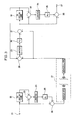
- Fig. 3 is a block diagram schematically showing a noise reduction circuit according to a first embodiment of the present invention.
- Fig. 4 is a graph for explaining the operational characteristics of the first embodiment of Fig. 3.
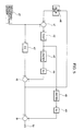
- Fig. 5 is a block diagram schematically showing a noise reduction circuit of a second embodiment of the present invention.
- Fig. 3 is a block diagram schematically showing a noise reduction circuit of a VTR according to a first embodiment of the present invention.
- a luminance signal to be recorded provided from a recording system circuit (not shown) of a VTR for example, is applied to a 1H delay line 22 implemented with a CCD delay line or the like through an input terminal 21 to be delayed by 1H.
- the 1H-delayed luminance signal is supplied to a negative input terminal of a subtractor 23.
- the current luminance signal provided to input terminal 21 is applied to a positive input terminal of subtractor 23, as well as to one input terminal of an adder 26.
- Subtractor 23 subtracts the luminance signal delayed by 1H at 1H delay line 22 from the current luminance signal from input terminal 21 to provide a signal component without line correlation.
- the extracted signal component is applied to a multiplier 25 having a coefficient of K1 via a limiter 24 to be attenuated in level.
- the signal component having the level attenuated is then applied to the other input terminal of adder 26.
- Adder 26 adds the signal component without line correlation to the current luminance signal. Hence, a luminance signal having a signal component without line correlation emphasized is provided from adder 26.
- Input terminal 21, 1H delay line 22, subtractor 23, limiter 24, multiplier 25 and adder 26 constitute a non-recursive type vertical emphasis circuit which applies a vertical emphasis to a luminance signal in a luminance signal recording system of a VTR.
- the vertical-emphasized luminance signal provided from adder 26 is applied to a recording/reproduction system 27 inclusively showing a recording system modulation circuit, a recording system magnetic head, a magnetic tape, a magnetic head for reproduction, a reproduction system demodulation circuit and the like, and is recorded on the magnetic tape.
- the luminance signal vertically emphasized and including noise generated at the time of recording/reproduction, which is reproduced from the magnetic tape at the time of reproduction, is applied to a positive input terminal of a subtractor 28 as well as to a positive input terminal of a subtractor 31.
- Subtractor 28 subtracts the reproduced luminance signal provided from a 1H delay line 32 from the reproduced luminance signal to extract a component without line correlation (mainly noise component).
- the extractive component is applied to a multiplier 30 of a coefficient of K2 via a limiter 29 to have its level attenuated.
- the attenuated component is then applied to a negative input terminal of a subtractor 31.
- the positive input terminal of subtractor 31 is supplied with the current reproduced luminance signal, whereby the component without line correlation is subtracted from the current reproduced luminance signal.
- a reproduced luminance signal having the component without line correlation reduced is applied to positive input terminals of subtractors 33 and 36, as well as to 1H delay line 32. Thereafter, the above described series of operation is repeated.
- Subtractor 28, limiter 29, multiplier 30, subtractor 31 and 1H delay line 32 constitute a recursive type noise reduction circuit. If coefficient K2 of multiplier 30 of the recursive type noise reduction circuit of the reproduction side is set to have a characteristic complimentary to that of coefficient K1 of the non-recursive type vertical emphasis circuit of the recording side, the recursive type noise reduction circuit of the reproduction side functions substantially as a vertical de-emphasis circuit subjecting a luminance signal to de-emphasis in the vertical direction.
- the reproduced luminance signal provided from subtractor 31 subjected to vertical de-emphasis is delayed by 1H in 1H delay line 32 and applied to the negative input terminal of subtractor 33.
- Subtractor 33 subtracts the reproduced luminance signal delayed by 1H from the reproduced luminance signal supplied from subtractor 31 to extract a noise component without line correlation.
- the extracted noise component is applied to a multiplier 35 of a coefficient K3 via a limiter 34 to be attenuated in level.
- the noise component is then applied to the negative input terminal of a subtractor 36.
- the positive input terminal of subtractor 36 is supplied with a reproduced luminance signal from subtractor 31, whereby subtractor 36 further subtracts the noise component from the reproduced luminance signal subjected to vertical de-emphasis.
- the reproduced luminance signal having the noise component reduced is provided from an output terminal 37.
- 1H delay line 32, subtractor 33, limiter 34, multiplier 35 and subtractor 36 constitute a non-recursive type noise reduction circuit.
- the recursive type noise reduction circuit of the preceding stage of the reproduction system performs mainly de-emphasis in the vertical direction to eliminate the need to increase the noise reduction amount of this recursive type noise reduction circuit, in comparison with the conventional example of Fig. 2 where vertical de-emphasis and noise reduction are carried out simultaneously. Therefore degradation of vertical resolution and increase of raining-like noise arising from the noise reduction circuit can be suppressed.
- the non-recursive type noise reduction circuit of the succeeding stage performs mainly reduction of noise components, allowing noise component reduction without particularly increasing the noise reduction amount of this non-recursive type noise reduction circuit. Therefore, noise having line correlation is not emphasized, and raining-like noise arising from this noise reduction circuit does not occur.
- Fig. 4 is a graph explaining the operation characteristic of the first embodiment of Fig. 3 in comparison with the conventional example of Fig. 2. The operation of the first embodiment will be explained in details with reference to Figs. 3 and 4.
- the transfer function of the non-recursive type recording system vertical emphasis circuit implemented with elements 21 to 26 of Fig. 3 is derived as in the following manner.
- V26 (t) V21 (t) + K1 (V21 (t) - V21 (t-T)) (1) where T represents 1H period.
- the transfer function H26 ( ⁇ ) of the recording system vertical emphasis circuit is expressed as below.
- the transfer function of the recursive type reproduction system vertical de-emphasis circuit implemented with elements 28 to 32 is derived as in the following manner.
- V31 (t) V27 (t) - K2 (V27 (t) - V31 (t - T)) (3)
- the transfer function H31 ( ⁇ ) of the reproduction system vertical de-emphasis circuit is expressed as below.
- the transfer function of the non-recursive type reproduction system noise reduction circuit implemented with elements 32 to 37 is derived as in the following manner.
- V37 (t) v31 (t) - K3 (V31 (t) - V31 (t-T)) (5)
- the transfer function H37 ( ⁇ ) of the reproduction system noise reduction circuit is expressed as below.
- K1 and K2 should be determined to establish: K1 ⁇ K2 / (1 - K2) (8)
- the recursive type noise reduction circuit shown in the conventional example of Fig. 2 does not include the elements corresponding to elements 33 to 36 of Fig. 3.
- the attenuation coefficients K1 and K2 of the recording system and the reproduction system are both specified as 0.5. In the convention example, . Accordingly, the de-emphasis amount of the vertical direction in the reproduction system is greater than the emphasis amount of the vertical direction in the recording system.
- the pass-band of a reproduced luminance signal of the first embodiment is wider than that of the conventional example to allow passage of original reproduced luminance signals in a wider range, when the attenuation amounts of the amplitudes between frequencies apart from each other by (1/2) f H (f H : horizontal frequency) are the same.
- the entire circuit structure of the embodiment of Fig. 3 is simplified by feature of the recursive type vertical de-emphasis circuit and the non-recursive type noise reduction circuit sharing a common 1H delay line 32.
- Fig. 5 is a block diagram schematically showing a noise reduction circuit of a second embodiment of the present invention. Depiction of the recording system emphasis circuit (elements 21 through 26 of Fig. 3) of the preceding stage of recording/reproduction system 27 is omitted in Fig. 5, and the description thereof is not repeated.
- the embodiment of Fig. 5 is basically formed by a recursive type noise reduction circuit of the preceding stage and a non-recursive type noise reduction circuit of the succeeding stage in a manner formed by similar to the aforementioned first embodiment.
- the difference from the first embodiment of Fig. 3 is that the second embodiment is implemented to share one adder as adders 28 and 33 of Fig. 3.
- a luminance signal, subjected to vertical emphasis and including noise, provided from recording/reproduction system 27 at the time of reproduction is applied to a positive input terminal of a subtractor 41, as well as to a positive input terminal of a subtractor 45 via a delay equalizer EQ.
- Subtractor 41 subtracts the output of a 1H delay line 46 from the reproduced luminance signal to extract a component not having line correlation.
- a chrominance signal resulting from the interleaving at the time of recording may possibly remains in the extracted component.
- the extracted component has the chrominance carrier removed by a trap circuit 42 which traps a signal of the subcarrier frequency f SC (3.58MHz) of a chrominance signal. This prevents leakage of chrominance signals and flicker at edge portions on the color picture arising from non-recursive type noise reduction circuits.
- the aforementioned delay equalizer EQ 47 is provided for the purpose of adjusting the time lag due to trap circuit 42.
- the component without line correlation provided from trap circuit 42 is applied to a multiplier 44 of a coefficient K2' via a limiter 43 to be attenuated in level.
- the attenuated component is then applied to a negative input terminal of subtractor 45.
- the positive input terminal of subtractor 45 is supplied with a reproduced luminance signal from recording/reproduction system 27.
- Subtractor 45 subtracts the component without line correlation from the current reproduced luminance signal.
- a reproduced luminance signal having the component without line correlation reduced is applied to the positive input terminal of subtractor 51, as well as to a 1H delay line 46.
- subtractor 41, trap circuit 42, limiter 43, multiplier 44, subtractor 45, 1H delay line 46 and delay equalizer EQ 47 constitute a recursive type noise reduction circuit (vertical de-emphasis circuit).
- the noise component without line correlation provided from trap circuit 42 is applied to a multiplier 49 of a coefficient K3' via a limiter 48 to be attenuated in level.
- the attenuated component is then applied to the negative input terminal of subtractor 51.
- the positive input terminal of subtractor 51 is supplied with a reproduced luminance signal from subtractor 45.
- Subtractor 51 subtracts the noise component from the reproduced luminance signal subjected to vertical de-emphasis.
- 1H delay line 46, subtractor 41, trap circuit 42, limiter 48, multiplier 49 and subtractor 51 constitute a non-recursive type noise reduction circuit.
- the coefficient K2' of multiplier 44 is preferably K2' ⁇ 1.0. Particularly, K2' ⁇ 0.5 is normally set. Coefficient K3' of multiplier 49 is set to K3' ⁇ 0.5.
- the multiplier 49 of the second embodiment is different from the multiplier 35 of the first embodiment in that the multiplier 49 receives as an input the noise component extracted from the recursive type noise reduction circuit.
- the coefficient K3' of the multiplier 49 of the second embodiment is set to be smaller than the coefficient K3 of the multiplier 35 of the first embodiment. For example, when the coefficient K3 of the multiplier 35 of the first embodiment is set to 0.164, the coefficient K3' of the multiplier 49 of the second embodiment is set to approximately 0.15.
- each of the recursive type noise reduction circuit and the non-recursive type noise reduction circuit comprises a limiter and a multiplier. By adjusting the characteristics thereof, it is possible to implement the order of the recursive type noise reduction circuit and the non-recursive type noise reduction circuit in reverse.
- the delay line in each embodiment is not limited to a 1H delay line and may be nH (n : natural number) delay line.
- reproduced luminance signals are subjected to vertical de-emphasis with a recursive type noise reduction circuit, as well as noise components being reduced with a non-recursive type noise reduction circuit, in reproducing luminance signals subjected to vertical emphasis at the time of recording, to eliminate the need to increase the noise reduction amount of each noise reduction circuit, and suppressing degradation of vertical resolution and increase of raining-like noise.
Landscapes
- Engineering & Computer Science (AREA)
- Multimedia (AREA)
- Signal Processing (AREA)
- Television Signal Processing For Recording (AREA)
- Signal Processing Not Specific To The Method Of Recording And Reproducing (AREA)
- Picture Signal Circuits (AREA)
Applications Claiming Priority (2)
| Application Number | Priority Date | Filing Date | Title |
|---|---|---|---|
| JP22362/90 | 1990-01-31 | ||
| JP2236290 | 1990-01-31 |
Publications (3)
| Publication Number | Publication Date |
|---|---|
| EP0440242A2 true EP0440242A2 (de) | 1991-08-07 |
| EP0440242A3 EP0440242A3 (en) | 1992-12-09 |
| EP0440242B1 EP0440242B1 (de) | 1996-09-25 |
Family
ID=12080518
Family Applications (1)
| Application Number | Title | Priority Date | Filing Date |
|---|---|---|---|
| EP91101311A Expired - Lifetime EP0440242B1 (de) | 1990-01-31 | 1991-01-31 | Schaltung zur Rauschverminderung für Videosignalaufzeichnungs- und -wiedergabegerät |
Country Status (4)
| Country | Link |
|---|---|
| US (1) | US5105275A (de) |
| EP (1) | EP0440242B1 (de) |
| KR (1) | KR100188460B1 (de) |
| DE (1) | DE69122277T2 (de) |
Cited By (3)
| Publication number | Priority date | Publication date | Assignee | Title |
|---|---|---|---|---|
| EP0546441A1 (de) * | 1991-12-10 | 1993-06-16 | Kabushiki Kaisha Toshiba | Rekursives Kammfilter |
| EP0580144A2 (de) * | 1992-07-21 | 1994-01-26 | Victor Company Of Japan, Limited | Vorrichtung zum Aufnehmen und Wiedergeben eines Videosignals mit Signalverarbeitung mit Vor- und Nachverzerrung |
| US5517322A (en) * | 1992-07-21 | 1996-05-14 | Victor Company Of Japan, Ltd. | Apparatus for recording and reproducing video signals with preemphasis and deemphasis processes |
Families Citing this family (5)
| Publication number | Priority date | Publication date | Assignee | Title |
|---|---|---|---|---|
| JP3054579B2 (ja) * | 1995-05-25 | 2000-06-19 | 三洋電機株式会社 | Vtrのイコライザ回路 |
| DE69614832T2 (de) * | 1996-05-24 | 2001-12-20 | Matsushita Electric Industrial Co., Ltd. | Verfahren und Schaltung zur Bestimmung eines Rauschwerts der repräsentativ ist für das Rauschen in einem Signal |
| US6381559B1 (en) * | 1996-08-12 | 2002-04-30 | The United States Of America As Represented By The Administrator Of The National Aeronautics And Space Administration | Empirical mode decomposition apparatus, method and article of manufacture for analyzing biological signals and performing curve fitting |
| US6738734B1 (en) | 1996-08-12 | 2004-05-18 | The United States Of America As Represented By The Administrator Of The National Aeronautics And Space Administration | Empirical mode decomposition apparatus, method and article of manufacture for analyzing biological signals and performing curve fitting |
| US6990436B1 (en) | 2003-11-28 | 2006-01-24 | The United States Of America As Represented By The Administrator Of The National Aeronautics And Space Administration | Computing frequency by using generalized zero-crossing applied to intrinsic mode functions |
Citations (8)
| Publication number | Priority date | Publication date | Assignee | Title |
|---|---|---|---|---|
| JPS57138276A (en) * | 1981-02-20 | 1982-08-26 | Hitachi Ltd | Video signal processing circuit |
| JPS57211885A (en) * | 1981-06-22 | 1982-12-25 | Victor Co Of Japan Ltd | Noise reduction circuit |
| EP0169052A2 (de) * | 1984-07-13 | 1986-01-22 | Victor Company Of Japan, Limited | Schaltung zur Verminderung des Rauschens für ein Videosignal |
| US4626927A (en) * | 1983-07-29 | 1986-12-02 | Victor Company Of Japan, Ltd. | Recording and reproducing apparatus for recording and reproducing a carrier chrominance signal with pre-emphasis and de-emphasis |
| US4641206A (en) * | 1983-03-01 | 1987-02-03 | Victor Company Of Japan, Ltd. | Video signal recording and reproducing apparatus including a noise reduction circuit |
| US4647960A (en) * | 1984-10-03 | 1987-03-03 | Hitachi, Ltd. | Vertical contour emphasis de-emphasis circuit |
| US4698696A (en) * | 1985-03-13 | 1987-10-06 | Victor Company Of Japan, Ltd. | Noise reduction circuit for video tape recording and playback apparatus |
| US4750037A (en) * | 1985-10-07 | 1988-06-07 | Victor Company Of Japan, Ltd. | Noise reduction system for video signal |
Family Cites Families (5)
| Publication number | Priority date | Publication date | Assignee | Title |
|---|---|---|---|---|
| JPS6030285A (ja) * | 1983-07-29 | 1985-02-15 | Victor Co Of Japan Ltd | 映像信号記録再生装置 |
| JPS6030296A (ja) * | 1983-07-29 | 1985-02-15 | Victor Co Of Japan Ltd | 映像信号記録装置及び映像信号記録再生装置 |
| DE3783820T2 (de) * | 1986-07-21 | 1993-08-26 | Victor Company Of Japan | Vorrichtung zum aufzeichnen und wiedergeben fuer ein videosignal. |
| US4860105A (en) * | 1987-05-22 | 1989-08-22 | Victor Company Of Japan, Ltd. | Noise Reducing circuit of a video signal |
| JP2508442B2 (ja) * | 1987-06-09 | 1996-06-19 | ソニー株式会社 | ノイズ除去回路 |
-
1991
- 1991-01-25 US US07/646,099 patent/US5105275A/en not_active Expired - Lifetime
- 1991-01-29 KR KR1019910001443A patent/KR100188460B1/ko not_active IP Right Cessation
- 1991-01-31 EP EP91101311A patent/EP0440242B1/de not_active Expired - Lifetime
- 1991-01-31 DE DE69122277T patent/DE69122277T2/de not_active Expired - Fee Related
Patent Citations (8)
| Publication number | Priority date | Publication date | Assignee | Title |
|---|---|---|---|---|
| JPS57138276A (en) * | 1981-02-20 | 1982-08-26 | Hitachi Ltd | Video signal processing circuit |
| JPS57211885A (en) * | 1981-06-22 | 1982-12-25 | Victor Co Of Japan Ltd | Noise reduction circuit |
| US4641206A (en) * | 1983-03-01 | 1987-02-03 | Victor Company Of Japan, Ltd. | Video signal recording and reproducing apparatus including a noise reduction circuit |
| US4626927A (en) * | 1983-07-29 | 1986-12-02 | Victor Company Of Japan, Ltd. | Recording and reproducing apparatus for recording and reproducing a carrier chrominance signal with pre-emphasis and de-emphasis |
| EP0169052A2 (de) * | 1984-07-13 | 1986-01-22 | Victor Company Of Japan, Limited | Schaltung zur Verminderung des Rauschens für ein Videosignal |
| US4647960A (en) * | 1984-10-03 | 1987-03-03 | Hitachi, Ltd. | Vertical contour emphasis de-emphasis circuit |
| US4698696A (en) * | 1985-03-13 | 1987-10-06 | Victor Company Of Japan, Ltd. | Noise reduction circuit for video tape recording and playback apparatus |
| US4750037A (en) * | 1985-10-07 | 1988-06-07 | Victor Company Of Japan, Ltd. | Noise reduction system for video signal |
Non-Patent Citations (1)
| Title |
|---|
| PATENT ABSTRACTS OF JAPAN vol. 7, no. 65 (E-165)18 March 1983 & JP-A-57 211 885 ( NIPPON VICTOR KK ) * |
Cited By (6)
| Publication number | Priority date | Publication date | Assignee | Title |
|---|---|---|---|---|
| EP0546441A1 (de) * | 1991-12-10 | 1993-06-16 | Kabushiki Kaisha Toshiba | Rekursives Kammfilter |
| US5311299A (en) * | 1991-12-10 | 1994-05-10 | Kabushiki Kaisha Toshiba | Recursive comb filter |
| EP0580144A2 (de) * | 1992-07-21 | 1994-01-26 | Victor Company Of Japan, Limited | Vorrichtung zum Aufnehmen und Wiedergeben eines Videosignals mit Signalverarbeitung mit Vor- und Nachverzerrung |
| EP0580144A3 (en) * | 1992-07-21 | 1994-07-20 | Victor Company Of Japan | Apparatus for recording and reproducing video signals with preemphasis and deemphasis processes |
| US5517322A (en) * | 1992-07-21 | 1996-05-14 | Victor Company Of Japan, Ltd. | Apparatus for recording and reproducing video signals with preemphasis and deemphasis processes |
| US5671066A (en) * | 1992-07-21 | 1997-09-23 | Victor Company Of Japan, Ltd. | Apparatus for recording and reproducing video signals with preemphasis and deemphasis processes |
Also Published As
| Publication number | Publication date |
|---|---|
| KR910014919A (ko) | 1991-08-31 |
| KR100188460B1 (ko) | 1999-06-01 |
| DE69122277D1 (de) | 1996-10-31 |
| EP0440242B1 (de) | 1996-09-25 |
| EP0440242A3 (en) | 1992-12-09 |
| US5105275A (en) | 1992-04-14 |
| DE69122277T2 (de) | 1997-04-03 |
Similar Documents
| Publication | Publication Date | Title |
|---|---|---|
| GB2112246A (en) | Carrier colour signal processing circuits | |
| EP0440242B1 (de) | Schaltung zur Rauschverminderung für Videosignalaufzeichnungs- und -wiedergabegerät | |
| EP0221684B1 (de) | Anordnung zur Verminderung des Rauschens bei einem Videosignal | |
| EP0183438B1 (de) | Vorrichtung zur Bearbeitung von Farbvideosignalen | |
| JPH0241951B2 (de) | ||
| JPH0115228B2 (de) | ||
| EP0186514B1 (de) | Kammfilter | |
| JPS6119198B2 (de) | ||
| EP0444838B1 (de) | Wiedergabegerät von Videosignalen | |
| JPH026710Y2 (de) | ||
| JPH051679B2 (de) | ||
| JP2731037B2 (ja) | ノイズ除去回路 | |
| JPS63115476A (ja) | 映像信号処理装置 | |
| JPS63266983A (ja) | 映像信号処理装置 | |
| JPH0349507Y2 (de) | ||
| JPH0258837B2 (de) | ||
| JP3048884B2 (ja) | Vtrの映像信号再生回路 | |
| JP2834140B2 (ja) | 映像信号記録方法 | |
| JPH0545116B2 (de) | ||
| JPS61218283A (ja) | 輝度信号再生装置及び記録再生装置 | |
| JPH0225597B2 (de) | ||
| JPS63229974A (ja) | 雑音除去装置 | |
| JPH0153832B2 (de) | ||
| JPH0153833B2 (de) | ||
| JPH04311191A (ja) | クロマ信号処理回路 |
Legal Events
| Date | Code | Title | Description |
|---|---|---|---|
| PUAI | Public reference made under article 153(3) epc to a published international application that has entered the european phase |
Free format text: ORIGINAL CODE: 0009012 |
|
| AK | Designated contracting states |
Kind code of ref document: A2 Designated state(s): DE FR GB |
|
| PUAL | Search report despatched |
Free format text: ORIGINAL CODE: 0009013 |
|
| AK | Designated contracting states |
Kind code of ref document: A3 Designated state(s): DE FR GB |
|
| 17P | Request for examination filed |
Effective date: 19921214 |
|
| 17Q | First examination report despatched |
Effective date: 19950331 |
|
| GRAG | Despatch of communication of intention to grant |
Free format text: ORIGINAL CODE: EPIDOS AGRA |
|
| GRAH | Despatch of communication of intention to grant a patent |
Free format text: ORIGINAL CODE: EPIDOS IGRA |
|
| GRAH | Despatch of communication of intention to grant a patent |
Free format text: ORIGINAL CODE: EPIDOS IGRA |
|
| GRAA | (expected) grant |
Free format text: ORIGINAL CODE: 0009210 |
|
| AK | Designated contracting states |
Kind code of ref document: B1 Designated state(s): DE FR GB |
|
| REF | Corresponds to: |
Ref document number: 69122277 Country of ref document: DE Date of ref document: 19961031 |
|
| ET | Fr: translation filed | ||
| PLBE | No opposition filed within time limit |
Free format text: ORIGINAL CODE: 0009261 |
|
| STAA | Information on the status of an ep patent application or granted ep patent |
Free format text: STATUS: NO OPPOSITION FILED WITHIN TIME LIMIT |
|
| 26N | No opposition filed | ||
| REG | Reference to a national code |
Ref country code: GB Ref legal event code: IF02 |
|
| PGFP | Annual fee paid to national office [announced via postgrant information from national office to epo] |
Ref country code: DE Payment date: 20070125 Year of fee payment: 17 |
|
| PGFP | Annual fee paid to national office [announced via postgrant information from national office to epo] |
Ref country code: GB Payment date: 20070131 Year of fee payment: 17 |
|
| PGFP | Annual fee paid to national office [announced via postgrant information from national office to epo] |
Ref country code: FR Payment date: 20070109 Year of fee payment: 17 |
|
| GBPC | Gb: european patent ceased through non-payment of renewal fee |
Effective date: 20080131 |
|
| PG25 | Lapsed in a contracting state [announced via postgrant information from national office to epo] |
Ref country code: DE Free format text: LAPSE BECAUSE OF NON-PAYMENT OF DUE FEES Effective date: 20080801 |
|
| REG | Reference to a national code |
Ref country code: FR Ref legal event code: ST Effective date: 20081029 |
|
| PG25 | Lapsed in a contracting state [announced via postgrant information from national office to epo] |
Ref country code: GB Free format text: LAPSE BECAUSE OF NON-PAYMENT OF DUE FEES Effective date: 20080131 |
|
| PG25 | Lapsed in a contracting state [announced via postgrant information from national office to epo] |
Ref country code: FR Free format text: LAPSE BECAUSE OF NON-PAYMENT OF DUE FEES Effective date: 20080131 |