EP0440140B1 - Rouleau pour appareil de lissage ou calandre - Google Patents
Rouleau pour appareil de lissage ou calandre Download PDFInfo
- Publication number
- EP0440140B1 EP0440140B1 EP91101085A EP91101085A EP0440140B1 EP 0440140 B1 EP0440140 B1 EP 0440140B1 EP 91101085 A EP91101085 A EP 91101085A EP 91101085 A EP91101085 A EP 91101085A EP 0440140 B1 EP0440140 B1 EP 0440140B1
- Authority
- EP
- European Patent Office
- Prior art keywords
- roller
- roll
- heat transfer
- heat
- peripheral
- Prior art date
- Legal status (The legal status is an assumption and is not a legal conclusion. Google has not performed a legal analysis and makes no representation as to the accuracy of the status listed.)
- Expired - Lifetime
Links
Images
Classifications
-
- D—TEXTILES; PAPER
- D21—PAPER-MAKING; PRODUCTION OF CELLULOSE
- D21G—CALENDERS; ACCESSORIES FOR PAPER-MAKING MACHINES
- D21G1/00—Calenders; Smoothing apparatus
- D21G1/02—Rolls; Their bearings
- D21G1/0253—Heating or cooling the rolls; Regulating the temperature
- D21G1/0266—Heating or cooling the rolls; Regulating the temperature using a heat-transfer fluid
-
- F—MECHANICAL ENGINEERING; LIGHTING; HEATING; WEAPONS; BLASTING
- F28—HEAT EXCHANGE IN GENERAL
- F28F—DETAILS OF HEAT-EXCHANGE AND HEAT-TRANSFER APPARATUS, OF GENERAL APPLICATION
- F28F5/00—Elements specially adapted for movement
- F28F5/02—Rotary drums or rollers
Definitions
- the present invention relates to a roller for a calender or a calender according to the preamble of claim 1.
- Such rollers are used for the production and processing of material webs, in particular for smoothing paper webs.
- Rolls of large dimensions in which a heat transfer medium is guided through bores (peripheral bores) running directly below the surface of the roller body are becoming increasingly important in recent times. This makes it possible to keep the path of heat from the heat transfer medium to the roll surface through the roll wall short and to enable effective heat transfer.
- Comparable rollers of conventional diameter can be found in DE-GM 84 36 546, DE-GM 84 10 839 and EU-0S 158 220 based on the two utility models.
- This has a roller body, peripheral bores on the roller body for the flow of a fluid heat transfer medium, a flange pin for each end of the roller body, supply and discharge lines for the fluid heat transfer medium in at least one flange pin and recesses for the distribution of the fluid heat transfer medium from the supply lines to the peripheral holes and from the peripheral holes to the discharge lines.
- the inner bore is filled with the heat transfer fluid during operation. This is not only expensive, but also has to be heated each time the calender is started and cooled each time it is shut down. This is not only a waste of energy, but also means an extension of the corresponding heating and cooling processes and thus an extension of the operational readiness.
- roller according to the invention further axial bores with a small diameter are provided near the inner bore, which has an enlarged diameter, in which a heat or coolant medium for tapping, through which the Carrier medium has been introduced into the roller flows back.
- the carrier liquid Since the rollers in question are generally driven rollers, the carrier liquid must be returned to the relevant pin after it has been introduced through the inlet pin and the peripheral bores have to flow through it, and must be removed via double sealing heads.
- the other pin is not available for this because it is required to drive the roller.
- the additional axial bores of small diameter that are additionally provided are very advantageous for returning the heat transfer fluid to the inlet spigot, since on the one hand this eliminates the usually regularly provided central roller bore and on the other hand additional weight savings are possible.
- a displacer body provided in the inner bore with its larger diameter is usually shrunk into the roller body. That is, the roller body is raised to a temperature which entails a certain increase in the diameter, in particular the inner diameter, of the roller. The displacement body is then pushed into the central bore of the roller body.
- the displacer is either a tube welded at both ends or an open tube at both ends, which is sealed with closures after the shrinking process. When the roller body is subsequently cooled, the roller body presses firmly against the displacement body.
- the displacement body can be completely dispensed with.
- This measure has the valuable advantages that the roller according to the invention can be manufactured much more easily and in a shorter time.
- the total weight of the roller can be reduced further as a result.
- the reliability of the roller in terms of tightness also increases.
- the heat or coolant initially flows through the central hole of the inlet pin into the roller and passes through connecting channels preferred to every third of the peripheral bores and flows through them in the axial direction along the roller.
- the carrier medium flows through connecting channels into an adjacent peripheral bore or into one of the other axial bores of small diameter.
- the carrier medium can be passed axially several times through the roller body before it is disposed of via the further axial bores of small diameter and the subsequent entry pin. The discarded carrier medium is then brought back to the desired temperature outside the roller and fed to the roller again.
- the inlet spigot is usually equipped with a double sealing head.
- three peripheral channels are connected to one another and to one of the further axial channels or bores for returning the carrier medium near the central bore.
- the radial arrangement of the peripheral channels or bores compared to the other axial bores has the advantage that the thermal compressive stresses in the interior of the roll are further reduced can be. This can be justified as follows: Because heat is removed from the surface of the roller, the heat transfer fluid also cools down during the repeated passage through the peripheral bores. With the triple-pass version listed above, the heat transfer fluid has reached its lowest temperature in the heating roller. By returning through the further axial bores in the inner roll area, the heat transfer medium warms up again somewhat due to the higher average temperature of the roll.
- both the radially inner and the radially outer regions of the roller body are simultaneously brought to the desired temperature during the heating phase. Thermal stresses from temporary temperature differences are avoided from the outset. This enables much faster heating times. Calculations have shown that it is possible to increase the heating rate to 4 ° C per minute. The heating-up time is reduced to just under an hour.
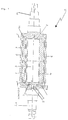
- FIG 1 shows an embodiment of the roller according to the invention, which is generally identified by reference number 10.
- the roller 10 is provided with an enlarged central bore which is completely filled with a displacement body 4.
- the roller body 1 of the roller 10 is provided with peripheral channels or bores 6 near the roller surface.
- the peripheral channels 6 are connected to further axial channels or bores 7 via connections 6c. These further axial bores 7 are in turn connected via an annular space 3 to the pin 2a, through which the heat transfer medium is introduced into the roller body 1 or disposed of therefrom.
- Fig. 1 it is indicated in the drawing that instead of a displacer 4, the enlarged central bore can also be welded very easily, for example, with sealing covers 8, which enables the roller 10 to be manufactured more easily.
- the heat transfer fluid is introduced into the roller body 1 via the inlet pin 2a.
- the heat transfer fluid is supplied to the peripheral channels 6 via connections 6e.
- the heat transfer fluid is then passed through the roller body 1 a further time either close to the roll surface or close to the surface of the enlarged central bore.
- the cooled or used heat transfer fluid is disposed of from the roller 10 via the inlet pin 2a in order to be brought back to the desired temperature outside the roller.
- the reference numeral 12 are fasteners, for. B. screws, bolts or the like, shown, with which the displacer 4 is connected to the roller body 1 of the roller 10.
- the connecting lines 6b allow fluid to be exchanged between adjacent peripheral channels 6.
- the radially extending connecting lines 6c ensure the return of the heat transfer fluid from the peripheral channels 6 to the further axial channels 7.
- the heat transfer fluid is passed through three peripheral channels 6 near the roller surface, in order to then be returned to the inlet pin 2a through an axial channel 7 near the surface of the enlarged central bore.
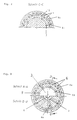
- the cross section shown in FIG. 3 through the roller body according to FIG. 1 shows two sectional planes. The cuts are made at the end of the roller 10 at which the entry pin 2a is located.
- Section AA shows essentially the same features as are shown from section CC in FIG. 2.
- Connecting lines 6d are also radially extending Connecting lines 6d, which connect the further axial channels or bores 7 to the annular space 3, from which the cooled or used heat transfer fluid is returned to the inlet pin 2a.
- the annular space 3 is connected to the return line 5.
- the lower section B-B in FIG. 3 shows the connection of every third peripheral channel 6 to the heat carrier feed 9 via connecting lines 6b.
- the peripheral bores 6 are connected to one another via connecting lines 6a.
- the sectional graphic D-D illustrates along which the cut shown in FIG. 1 runs through the roller body 1 of the roller 10.
- the heat transfer fluid After the heat transfer fluid has entered the roller body via the inlet pin 2a or the feed line 9 running through it (FIG. 1), the heat transfer fluid is introduced into every third peripheral channel 6 via the connection lines 6e (FIG. 3). The heat transfer fluid is now conveyed in the axial direction through the peripherally running channels 6 in order to be transferred at the roller end of the drive journal 2b (FIG. 2) via connecting lines 6a into adjacent peripheral channels 6. The heat transfer fluid is again passed axially through the roller body 1 through this adjacent peripheral channel 6. At the roller end of the inlet pin 2a, the heat transfer fluid is transferred once more via a circumferentially extending connecting line 6a into an adjacent peripheral bore.
- the heat transfer fluid is passed on to the further axial bores 7 via radially extending connecting lines 6c (FIG. 1, FIG. 2). After the heat transfer fluid has passed through the further axial bores 7, it is conveyed into the annular space 3 via the radially inwardly extending connecting lines 6d. From the annular space 3, the cooled or used heat transfer fluid is passed via the disposal line 5 through the inlet pin 2a from the roller 10.
Landscapes
- Engineering & Computer Science (AREA)
- Physics & Mathematics (AREA)
- Thermal Sciences (AREA)
- Mechanical Engineering (AREA)
- General Engineering & Computer Science (AREA)
- Rolls And Other Rotary Bodies (AREA)
Claims (6)
- Cylindre pour lisseuse ou calandre, comportant:a) un corps cylindrique,b) un tourillon à bride à chaque extrémité du corps cylindrique,c) un alésage central obturé, ménagé dans le corps cylindrique, etd) des conduits périphériques ménagés dans le corps cylindrique, à proximité de sa surface, pour le passage d'un agent caloporteur fluide,
caractérisé en ce quee) d'autres conduits axiaux (7) de petit diamètre, permettant le passage de l'agent caloporteur, sont prévus dans le corps cylindrique (1), à proximité de l'alésage central. - Cylindre suivant la revendication 1, caractérisé en ce que l'alésage central est entièrement rempli avec un corps de refoulement.
- Cylindre suivant la revendication 1, caractérisé en ce que l'alésage central est condamné par des joints plats (8).
- Cylindre suivant l'une des revendications 1 à 3, caractérisé en ce que l'agent caloporteur retourne, en traversant les autres conduits axiaux (7) de faible diamètre, vers le tourillon à bride (2a), par lequel l'agent caloporteur a pénétré dans le cylindre (10).
- Cylindre suivant l'une des revendications 1 à 3, caractérisé en ce que l'agent caloporteur retourne, en traversant les conduits périphériques (6), vers le tourillon à bride (2a), par lequel l'agent caloporteur a pénétré dans le cylindre (10).
- Cylindre suivant l'une des revendications 1 à 5, caractérisé en ce que l'agent caloporteur parcourt de une à trois fois les conduits périphériques (6) et les autres conduits axiaux (7).
Applications Claiming Priority (2)
| Application Number | Priority Date | Filing Date | Title |
|---|---|---|---|
| DE4002530A DE4002530A1 (de) | 1990-01-29 | 1990-01-29 | Walze fuer ein glaettwerk oder einen kalander |
| DE4002530 | 1990-01-29 |
Publications (3)
| Publication Number | Publication Date |
|---|---|
| EP0440140A2 EP0440140A2 (fr) | 1991-08-07 |
| EP0440140A3 EP0440140A3 (en) | 1992-01-15 |
| EP0440140B1 true EP0440140B1 (fr) | 1994-06-08 |
Family
ID=6398980
Family Applications (1)
| Application Number | Title | Priority Date | Filing Date |
|---|---|---|---|
| EP91101085A Expired - Lifetime EP0440140B1 (fr) | 1990-01-29 | 1991-01-28 | Rouleau pour appareil de lissage ou calandre |
Country Status (3)
| Country | Link |
|---|---|
| EP (1) | EP0440140B1 (fr) |
| DE (2) | DE4002530A1 (fr) |
| FI (1) | FI910383A (fr) |
Families Citing this family (10)
| Publication number | Priority date | Publication date | Assignee | Title |
|---|---|---|---|---|
| ES2136272T3 (es) * | 1993-11-12 | 1999-11-16 | Unilever Nv | Procedimientos de ensayo y dispositivos para los mismos. |
| DE4407239A1 (de) * | 1994-03-04 | 1995-09-07 | Schwaebische Huettenwerke Gmbh | Dampfbeheizte Walze |
| DE19513500C2 (de) * | 1995-04-10 | 1998-05-14 | Schwaebische Huettenwerke Gmbh | Walze mit einstellbarer Form |
| DE19707876C2 (de) * | 1997-02-27 | 2002-09-26 | Voith Paper Patent Gmbh | Walzenanordnung |
| DE29710040U1 (de) * | 1997-06-09 | 1998-10-08 | Kuesters Eduard Maschf | Beheizbare Walze |
| FI105115B (fi) * | 1998-12-02 | 2000-06-15 | Valmet Corp | Kuumennettava tela |
| DE29918267U1 (de) * | 1999-10-19 | 2000-01-20 | Walzen Irle Gmbh | Temperierbare Walze, insbesondere beheizbare Kalanderwalze |
| DE102010044943A1 (de) * | 2010-09-10 | 2012-03-15 | Leonhard Breitenbach Gmbh | Walze, insbesondere Kalanderwalze |
| CN110053313A (zh) * | 2019-03-13 | 2019-07-26 | 抚顺东旭精工制辊科技有限公司 | 一种真空吸附瓦楞辊 |
| EP3929353B1 (fr) * | 2020-06-24 | 2023-05-10 | Valmet Technologies Oy | Rouleau thermique pour une machine de fabrication d'une bande de matière fibreuse |
Family Cites Families (4)
| Publication number | Priority date | Publication date | Assignee | Title |
|---|---|---|---|---|
| US3120867A (en) * | 1961-07-27 | 1964-02-11 | Nash John Crandon | Heat exchange roll |
| ATE83515T1 (de) * | 1984-04-06 | 1993-01-15 | Walzen Irle Gmbh | Mittels eines waerme uebertragenden mediums beheizbare kalanderwalze. |
| DE3716223A1 (de) * | 1987-04-02 | 1988-10-13 | Schwaebische Huettenwerke Gmbh | Beheizbare glaettwerk- oder kalanderwalze |
| DE9000980U1 (fr) * | 1990-01-29 | 1990-05-10 | Schwaebische Huettenwerke Gmbh, 7080 Aalen, De |
-
1990
- 1990-01-29 DE DE4002530A patent/DE4002530A1/de not_active Withdrawn
-
1991
- 1991-01-25 FI FI910383A patent/FI910383A/fi not_active Application Discontinuation
- 1991-01-28 EP EP91101085A patent/EP0440140B1/fr not_active Expired - Lifetime
- 1991-01-28 DE DE59101817T patent/DE59101817D1/de not_active Expired - Fee Related
Also Published As
| Publication number | Publication date |
|---|---|
| EP0440140A2 (fr) | 1991-08-07 |
| DE4002530A1 (de) | 1991-08-01 |
| DE59101817D1 (de) | 1994-07-14 |
| FI910383A0 (fi) | 1991-01-25 |
| FI910383A (fi) | 1991-07-30 |
| EP0440140A3 (en) | 1992-01-15 |
Similar Documents
| Publication | Publication Date | Title |
|---|---|---|
| EP1218187B1 (fr) | Cylindre de presse rotative | |
| DE3014891C2 (fr) | ||
| DE3138274A1 (de) | Vorrichtung zum haerten von stahlrohren | |
| EP0440140B1 (fr) | Rouleau pour appareil de lissage ou calandre | |
| EP0156236B1 (fr) | Rouleau pour le traitement d'un matériau plat en bande | |
| EP0340503A2 (fr) | Rouleau chauffé | |
| DE4313379C2 (de) | Heizwalze | |
| WO2010054997A1 (fr) | Arbre pour un moteur électrique, en particulier pour un générateur moteur | |
| EP1661624A1 (fr) | Cylindre, en particulier cylindre rotatif pour une structure à cinq cylindres utilisée dans la fabrication du chocolat | |
| EP0411427B1 (fr) | Rouleau pour le traitement par la chaleur et par pression d'une matière en bande | |
| EP0285081B1 (fr) | Rouleau chauffé pour calandre ou appareil de lissage | |
| EP1347851B8 (fr) | Rouleau de coulee a profil variable pour couler un feuillard metallique dans une installation a rouleaux de coulee | |
| EP1247005B1 (fr) | Arbre se presentant sous forme de piece mecanique avec des conduites integrees | |
| EP1815981A2 (fr) | Dispositif et procédé pour réguler la température d'un élément rotatif | |
| EP2545311B1 (fr) | Répartiteur destiné à des systèmes de régulation thermique de batiments ou de locaux, ledit répartiteur étant muni d'une tubulure de répartition | |
| EP3439789B1 (fr) | Buse rotative à haute pression | |
| WO2020216619A1 (fr) | Cylindre d'extrusion comportant un guidage d'agent réfrigérant ou chauffant | |
| EP1033221B1 (fr) | Procédé de fabrication d'un logement de soupape sans enlèvement de copeaux | |
| DE19507864B4 (de) | Scherbeneisautomat | |
| DE19651938B4 (de) | Kalanderwalzen oder Glättwalzen | |
| DE2003356A1 (de) | Verfahren und Einrichtung fuer den Bewegungsantrieb eines Werkstuecks | |
| EP1958771B1 (fr) | Dispositif de régulation thermique d'une presse d'impression | |
| DE3207193C2 (de) | Extruderzylinderabschnitt in einem Mehrschneckenextruder für Kunststoff | |
| EP0087505B1 (fr) | Dispositif pour le traitement de pièces, en particulier pour l'ébavurage thermique | |
| DE2751428A1 (de) | Zylinderauskleidung |
Legal Events
| Date | Code | Title | Description |
|---|---|---|---|
| PUAI | Public reference made under article 153(3) epc to a published international application that has entered the european phase |
Free format text: ORIGINAL CODE: 0009012 |
|
| AK | Designated contracting states |
Kind code of ref document: A2 Designated state(s): CH DE GB IT LI SE |
|
| PUAL | Search report despatched |
Free format text: ORIGINAL CODE: 0009013 |
|
| AK | Designated contracting states |
Kind code of ref document: A3 Designated state(s): CH DE GB IT LI SE |
|
| 17P | Request for examination filed |
Effective date: 19920304 |
|
| 17Q | First examination report despatched |
Effective date: 19931015 |
|
| GRAA | (expected) grant |
Free format text: ORIGINAL CODE: 0009210 |
|
| ITF | It: translation for a ep patent filed |
Owner name: BARZANO' E ZANARDO MILANO S.P.A. |
|
| AK | Designated contracting states |
Kind code of ref document: B1 Designated state(s): CH DE GB IT LI SE |
|
| GBT | Gb: translation of ep patent filed (gb section 77(6)(a)/1977) |
Effective date: 19940610 |
|
| REF | Corresponds to: |
Ref document number: 59101817 Country of ref document: DE Date of ref document: 19940714 |
|
| EAL | Se: european patent in force in sweden |
Ref document number: 91101085.8 |
|
| PGFP | Annual fee paid to national office [announced via postgrant information from national office to epo] |
Ref country code: DE Payment date: 19950227 Year of fee payment: 5 |
|
| PLBE | No opposition filed within time limit |
Free format text: ORIGINAL CODE: 0009261 |
|
| STAA | Information on the status of an ep patent application or granted ep patent |
Free format text: STATUS: NO OPPOSITION FILED WITHIN TIME LIMIT |
|
| 26N | No opposition filed | ||
| PGFP | Annual fee paid to national office [announced via postgrant information from national office to epo] |
Ref country code: GB Payment date: 19960108 Year of fee payment: 6 |
|
| PGFP | Annual fee paid to national office [announced via postgrant information from national office to epo] |
Ref country code: SE Payment date: 19960122 Year of fee payment: 6 |
|
| PGFP | Annual fee paid to national office [announced via postgrant information from national office to epo] |
Ref country code: CH Payment date: 19960124 Year of fee payment: 6 |
|
| PG25 | Lapsed in a contracting state [announced via postgrant information from national office to epo] |
Ref country code: DE Effective date: 19961001 |
|
| PG25 | Lapsed in a contracting state [announced via postgrant information from national office to epo] |
Ref country code: GB Effective date: 19970128 |
|
| PG25 | Lapsed in a contracting state [announced via postgrant information from national office to epo] |
Ref country code: SE Effective date: 19970129 |
|
| PG25 | Lapsed in a contracting state [announced via postgrant information from national office to epo] |
Ref country code: LI Effective date: 19970131 Ref country code: CH Effective date: 19970131 |
|
| REG | Reference to a national code |
Ref country code: CH Ref legal event code: PL |
|
| GBPC | Gb: european patent ceased through non-payment of renewal fee |
Effective date: 19970128 |
|
| EUG | Se: european patent has lapsed |
Ref document number: 91101085.8 |
|
| PG25 | Lapsed in a contracting state [announced via postgrant information from national office to epo] |
Ref country code: IT Free format text: LAPSE BECAUSE OF NON-PAYMENT OF DUE FEES;WARNING: LAPSES OF ITALIAN PATENTS WITH EFFECTIVE DATE BEFORE 2007 MAY HAVE OCCURRED AT ANY TIME BEFORE 2007. THE CORRECT EFFECTIVE DATE MAY BE DIFFERENT FROM THE ONE RECORDED. Effective date: 20050128 |