EP0439892A2 - Anordnung zur Alignierung amorpher Erinnerungspolymere - Google Patents
Anordnung zur Alignierung amorpher Erinnerungspolymere Download PDFInfo
- Publication number
- EP0439892A2 EP0439892A2 EP90304651A EP90304651A EP0439892A2 EP 0439892 A2 EP0439892 A2 EP 0439892A2 EP 90304651 A EP90304651 A EP 90304651A EP 90304651 A EP90304651 A EP 90304651A EP 0439892 A2 EP0439892 A2 EP 0439892A2
- Authority
- EP
- European Patent Office
- Prior art keywords
- shape
- cavity
- mass
- articles
- cross
- Prior art date
- Legal status (The legal status is an assumption and is not a legal conclusion. Google has not performed a legal analysis and makes no representation as to the accuracy of the status listed.)
- Withdrawn
Links
- 229920000642 polymer Polymers 0.000 title claims abstract description 109
- 238000000034 method Methods 0.000 claims abstract description 55
- 239000000203 mixture Substances 0.000 claims description 31
- 239000002904 solvent Substances 0.000 claims description 30
- 230000008961 swelling Effects 0.000 claims description 29
- 239000013307 optical fiber Substances 0.000 claims description 28
- 239000000178 monomer Substances 0.000 claims description 27
- 238000004132 cross linking Methods 0.000 claims description 21
- 239000007788 liquid Substances 0.000 claims description 12
- 239000002861 polymer material Substances 0.000 claims description 12
- 239000002243 precursor Substances 0.000 claims description 7
- 239000007787 solid Substances 0.000 claims description 6
- 238000003780 insertion Methods 0.000 claims description 5
- 230000037431 insertion Effects 0.000 claims description 5
- CERQOIWHTDAKMF-UHFFFAOYSA-N Methacrylic acid Chemical compound CC(=C)C(O)=O CERQOIWHTDAKMF-UHFFFAOYSA-N 0.000 claims description 4
- 230000009477 glass transition Effects 0.000 claims description 4
- NIXOWILDQLNWCW-UHFFFAOYSA-N Acrylic acid Chemical class OC(=O)C=C NIXOWILDQLNWCW-UHFFFAOYSA-N 0.000 claims description 3
- 230000015572 biosynthetic process Effects 0.000 claims description 3
- 238000006116 polymerization reaction Methods 0.000 claims description 3
- 238000004017 vitrification Methods 0.000 claims description 3
- 230000000994 depressogenic effect Effects 0.000 claims description 2
- 150000002148 esters Chemical class 0.000 claims description 2
- 238000002360 preparation method Methods 0.000 claims description 2
- 229920000431 shape-memory polymer Polymers 0.000 claims 11
- 229920006037 cross link polymer Polymers 0.000 claims 3
- PPBRXRYQALVLMV-UHFFFAOYSA-N Styrene Chemical compound C=CC1=CC=CC=C1 PPBRXRYQALVLMV-UHFFFAOYSA-N 0.000 claims 2
- 150000001298 alcohols Chemical class 0.000 claims 1
- 125000004432 carbon atom Chemical group C* 0.000 claims 1
- 238000005304 joining Methods 0.000 claims 1
- 229920000620 organic polymer Polymers 0.000 claims 1
- 230000000379 polymerizing effect Effects 0.000 claims 1
- 229920013730 reactive polymer Polymers 0.000 claims 1
- 239000000463 material Substances 0.000 description 31
- YXFVVABEGXRONW-UHFFFAOYSA-N Toluene Chemical compound CC1=CC=CC=C1 YXFVVABEGXRONW-UHFFFAOYSA-N 0.000 description 30
- OKKJLVBELUTLKV-UHFFFAOYSA-N Methanol Chemical compound OC OKKJLVBELUTLKV-UHFFFAOYSA-N 0.000 description 18
- 230000003287 optical effect Effects 0.000 description 18
- 239000000835 fiber Substances 0.000 description 16
- 229920005989 resin Polymers 0.000 description 15
- 239000011347 resin Substances 0.000 description 15
- -1 polypropylene Polymers 0.000 description 14
- 230000007704 transition Effects 0.000 description 14
- 230000008901 benefit Effects 0.000 description 12
- 230000008018 melting Effects 0.000 description 11
- 238000002844 melting Methods 0.000 description 11
- 229910052751 metal Inorganic materials 0.000 description 11
- 239000002184 metal Substances 0.000 description 11
- 150000002739 metals Chemical class 0.000 description 10
- PEDCQBHIVMGVHV-UHFFFAOYSA-N Glycerine Chemical compound OCC(O)CO PEDCQBHIVMGVHV-UHFFFAOYSA-N 0.000 description 9
- 239000004743 Polypropylene Substances 0.000 description 9
- 235000013902 inosinic acid Nutrition 0.000 description 9
- 229920001155 polypropylene Polymers 0.000 description 9
- IJGRMHOSHXDMSA-UHFFFAOYSA-N Atomic nitrogen Chemical compound N#N IJGRMHOSHXDMSA-UHFFFAOYSA-N 0.000 description 8
- 239000000853 adhesive Substances 0.000 description 8
- 230000001070 adhesive effect Effects 0.000 description 8
- ISAOCJYIOMOJEB-UHFFFAOYSA-N benzoin Chemical compound C=1C=CC=CC=1C(O)C(=O)C1=CC=CC=C1 ISAOCJYIOMOJEB-UHFFFAOYSA-N 0.000 description 8
- 239000012530 fluid Substances 0.000 description 8
- 239000011521 glass Substances 0.000 description 8
- 238000004519 manufacturing process Methods 0.000 description 7
- 239000004014 plasticizer Substances 0.000 description 7
- 238000007711 solidification Methods 0.000 description 7
- 230000008023 solidification Effects 0.000 description 7
- 238000001723 curing Methods 0.000 description 6
- 239000003365 glass fiber Substances 0.000 description 6
- 230000035882 stress Effects 0.000 description 6
- 230000008602 contraction Effects 0.000 description 5
- 238000010438 heat treatment Methods 0.000 description 5
- 230000003993 interaction Effects 0.000 description 5
- 239000010935 stainless steel Substances 0.000 description 5
- 229910001220 stainless steel Inorganic materials 0.000 description 5
- VVQNEPGJFQJSBK-UHFFFAOYSA-N Methyl methacrylate Chemical compound COC(=O)C(C)=C VVQNEPGJFQJSBK-UHFFFAOYSA-N 0.000 description 4
- 244000028419 Styrax benzoin Species 0.000 description 4
- 235000000126 Styrax benzoin Nutrition 0.000 description 4
- 235000008411 Sumatra benzointree Nutrition 0.000 description 4
- 229960002130 benzoin Drugs 0.000 description 4
- 230000005540 biological transmission Effects 0.000 description 4
- 239000003085 diluting agent Substances 0.000 description 4
- 230000006355 external stress Effects 0.000 description 4
- 235000019382 gum benzoic Nutrition 0.000 description 4
- 238000000465 moulding Methods 0.000 description 4
- 229910052757 nitrogen Inorganic materials 0.000 description 4
- 229920003023 plastic Polymers 0.000 description 4
- 239000004033 plastic Substances 0.000 description 4
- SVONRAPFKPVNKG-UHFFFAOYSA-N 2-ethoxyethyl acetate Chemical compound CCOCCOC(C)=O SVONRAPFKPVNKG-UHFFFAOYSA-N 0.000 description 3
- 239000004593 Epoxy Substances 0.000 description 3
- 239000004809 Teflon Substances 0.000 description 3
- 229920006362 Teflon® Polymers 0.000 description 3
- 230000008859 change Effects 0.000 description 3
- 238000006243 chemical reaction Methods 0.000 description 3
- 238000001816 cooling Methods 0.000 description 3
- 229920001577 copolymer Polymers 0.000 description 3
- 238000000354 decomposition reaction Methods 0.000 description 3
- 230000007423 decrease Effects 0.000 description 3
- 230000003247 decreasing effect Effects 0.000 description 3
- 229920006332 epoxy adhesive Polymers 0.000 description 3
- STVZJERGLQHEKB-UHFFFAOYSA-N ethylene glycol dimethacrylate Substances CC(=C)C(=O)OCCOC(=O)C(C)=C STVZJERGLQHEKB-UHFFFAOYSA-N 0.000 description 3
- 230000004927 fusion Effects 0.000 description 3
- 238000009434 installation Methods 0.000 description 3
- QSHDDOUJBYECFT-UHFFFAOYSA-N mercury Chemical compound [Hg] QSHDDOUJBYECFT-UHFFFAOYSA-N 0.000 description 3
- 229910052753 mercury Inorganic materials 0.000 description 3
- 229920001778 nylon Polymers 0.000 description 3
- 230000010399 physical interaction Effects 0.000 description 3
- 238000011084 recovery Methods 0.000 description 3
- 230000002441 reversible effect Effects 0.000 description 3
- 238000009987 spinning Methods 0.000 description 3
- BFKJFAAPBSQJPD-UHFFFAOYSA-N tetrafluoroethene Chemical compound FC(F)=C(F)F BFKJFAAPBSQJPD-UHFFFAOYSA-N 0.000 description 3
- 230000000930 thermomechanical effect Effects 0.000 description 3
- XLYOFNOQVPJJNP-UHFFFAOYSA-N water Substances O XLYOFNOQVPJJNP-UHFFFAOYSA-N 0.000 description 3
- DTGKSKDOIYIVQL-WEDXCCLWSA-N (+)-borneol Chemical compound C1C[C@@]2(C)[C@@H](O)C[C@@H]1C2(C)C DTGKSKDOIYIVQL-WEDXCCLWSA-N 0.000 description 2
- OZAIFHULBGXAKX-UHFFFAOYSA-N 2-(2-cyanopropan-2-yldiazenyl)-2-methylpropanenitrile Chemical compound N#CC(C)(C)N=NC(C)(C)C#N OZAIFHULBGXAKX-UHFFFAOYSA-N 0.000 description 2
- 125000003345 AMP group Chemical group 0.000 description 2
- CSCPPACGZOOCGX-UHFFFAOYSA-N Acetone Chemical compound CC(C)=O CSCPPACGZOOCGX-UHFFFAOYSA-N 0.000 description 2
- OMPJBNCRMGITSC-UHFFFAOYSA-N Benzoylperoxide Chemical compound C=1C=CC=CC=1C(=O)OOC(=O)C1=CC=CC=C1 OMPJBNCRMGITSC-UHFFFAOYSA-N 0.000 description 2
- IERHLVCPSMICTF-XVFCMESISA-N CMP group Chemical group P(=O)(O)(O)OC[C@@H]1[C@H]([C@H]([C@@H](O1)N1C(=O)N=C(N)C=C1)O)O IERHLVCPSMICTF-XVFCMESISA-N 0.000 description 2
- LFQSCWFLJHTTHZ-UHFFFAOYSA-N Ethanol Chemical compound CCO LFQSCWFLJHTTHZ-UHFFFAOYSA-N 0.000 description 2
- 239000004606 Fillers/Extenders Substances 0.000 description 2
- KRHYYFGTRYWZRS-UHFFFAOYSA-N Fluorane Chemical compound F KRHYYFGTRYWZRS-UHFFFAOYSA-N 0.000 description 2
- 239000004677 Nylon Substances 0.000 description 2
- 229920002292 Nylon 6 Polymers 0.000 description 2
- 239000004952 Polyamide Substances 0.000 description 2
- 238000002441 X-ray diffraction Methods 0.000 description 2
- IAXXETNIOYFMLW-COPLHBTASA-N [(1s,3s,4s)-4,7,7-trimethyl-3-bicyclo[2.2.1]heptanyl] 2-methylprop-2-enoate Chemical compound C1C[C@]2(C)[C@@H](OC(=O)C(=C)C)C[C@H]1C2(C)C IAXXETNIOYFMLW-COPLHBTASA-N 0.000 description 2
- 230000006399 behavior Effects 0.000 description 2
- 235000019400 benzoyl peroxide Nutrition 0.000 description 2
- CKDOCTFBFTVPSN-UHFFFAOYSA-N borneol Natural products C1CC2(C)C(C)CC1C2(C)C CKDOCTFBFTVPSN-UHFFFAOYSA-N 0.000 description 2
- 230000015556 catabolic process Effects 0.000 description 2
- 239000013317 conjugated microporous polymer Substances 0.000 description 2
- 238000007334 copolymerization reaction Methods 0.000 description 2
- 238000002425 crystallisation Methods 0.000 description 2
- 230000008025 crystallization Effects 0.000 description 2
- 238000006731 degradation reaction Methods 0.000 description 2
- DTGKSKDOIYIVQL-UHFFFAOYSA-N dl-isoborneol Natural products C1CC2(C)C(O)CC1C2(C)C DTGKSKDOIYIVQL-UHFFFAOYSA-N 0.000 description 2
- 239000003822 epoxy resin Substances 0.000 description 2
- 238000005530 etching Methods 0.000 description 2
- 229920006227 ethylene-grafted-maleic anhydride Polymers 0.000 description 2
- 239000000945 filler Substances 0.000 description 2
- 238000001746 injection moulding Methods 0.000 description 2
- 229940119545 isobornyl methacrylate Drugs 0.000 description 2
- 230000033001 locomotion Effects 0.000 description 2
- BDAGIHXWWSANSR-UHFFFAOYSA-N methanoic acid Natural products OC=O BDAGIHXWWSANSR-UHFFFAOYSA-N 0.000 description 2
- 238000010137 moulding (plastic) Methods 0.000 description 2
- 210000003643 myeloid progenitor cell Anatomy 0.000 description 2
- 239000002245 particle Substances 0.000 description 2
- 229920003229 poly(methyl methacrylate) Polymers 0.000 description 2
- 229920002239 polyacrylonitrile Polymers 0.000 description 2
- 229920002647 polyamide Polymers 0.000 description 2
- 229920000647 polyepoxide Polymers 0.000 description 2
- 239000012704 polymeric precursor Substances 0.000 description 2
- 239000004926 polymethyl methacrylate Substances 0.000 description 2
- 229920002635 polyurethane Polymers 0.000 description 2
- 239000004814 polyurethane Substances 0.000 description 2
- 230000008569 process Effects 0.000 description 2
- FBCQUCJYYPMKRO-UHFFFAOYSA-N prop-2-enyl 2-methylprop-2-enoate Chemical compound CC(=C)C(=O)OCC=C FBCQUCJYYPMKRO-UHFFFAOYSA-N 0.000 description 2
- 230000001681 protective effect Effects 0.000 description 2
- 238000007493 shaping process Methods 0.000 description 2
- 239000000126 substance Substances 0.000 description 2
- 238000013519 translation Methods 0.000 description 2
- REPVLJRCJUVQFA-UHFFFAOYSA-N (-)-isopinocampheol Natural products C1C(O)C(C)C2C(C)(C)C1C2 REPVLJRCJUVQFA-UHFFFAOYSA-N 0.000 description 1
- LTHJXDSHSVNJKG-UHFFFAOYSA-N 2-[2-[2-[2-(2-methylprop-2-enoyloxy)ethoxy]ethoxy]ethoxy]ethyl 2-methylprop-2-enoate Chemical compound CC(=C)C(=O)OCCOCCOCCOCCOC(=O)C(C)=C LTHJXDSHSVNJKG-UHFFFAOYSA-N 0.000 description 1
- KUDUQBURMYMBIJ-UHFFFAOYSA-N 2-prop-2-enoyloxyethyl prop-2-enoate Chemical compound C=CC(=O)OCCOC(=O)C=C KUDUQBURMYMBIJ-UHFFFAOYSA-N 0.000 description 1
- 125000003903 2-propenyl group Chemical group [H]C([*])([H])C([H])=C([H])[H] 0.000 description 1
- OSWFIVFLDKOXQC-UHFFFAOYSA-N 4-(3-methoxyphenyl)aniline Chemical compound COC1=CC=CC(C=2C=CC(N)=CC=2)=C1 OSWFIVFLDKOXQC-UHFFFAOYSA-N 0.000 description 1
- DBCAQXHNJOFNGC-UHFFFAOYSA-N 4-bromo-1,1,1-trifluorobutane Chemical compound FC(F)(F)CCCBr DBCAQXHNJOFNGC-UHFFFAOYSA-N 0.000 description 1
- QTBSBXVTEAMEQO-UHFFFAOYSA-M Acetate Chemical compound CC([O-])=O QTBSBXVTEAMEQO-UHFFFAOYSA-M 0.000 description 1
- NLHHRLWOUZZQLW-UHFFFAOYSA-N Acrylonitrile Chemical compound C=CC#N NLHHRLWOUZZQLW-UHFFFAOYSA-N 0.000 description 1
- OKTJSMMVPCPJKN-UHFFFAOYSA-N Carbon Chemical compound [C] OKTJSMMVPCPJKN-UHFFFAOYSA-N 0.000 description 1
- 239000004971 Cross linker Substances 0.000 description 1
- VGGSQFUCUMXWEO-UHFFFAOYSA-N Ethene Chemical compound C=C VGGSQFUCUMXWEO-UHFFFAOYSA-N 0.000 description 1
- 239000005977 Ethylene Substances 0.000 description 1
- DTGKSKDOIYIVQL-MRTMQBJTSA-N Isoborneol Natural products C1C[C@@]2(C)[C@H](O)C[C@@H]1C2(C)C DTGKSKDOIYIVQL-MRTMQBJTSA-N 0.000 description 1
- 239000002202 Polyethylene glycol Substances 0.000 description 1
- 239000004642 Polyimide Substances 0.000 description 1
- 239000004793 Polystyrene Substances 0.000 description 1
- 229920002396 Polyurea Polymers 0.000 description 1
- VYPSYNLAJGMNEJ-UHFFFAOYSA-N Silicium dioxide Chemical compound O=[Si]=O VYPSYNLAJGMNEJ-UHFFFAOYSA-N 0.000 description 1
- 229910000831 Steel Inorganic materials 0.000 description 1
- 238000003848 UV Light-Curing Methods 0.000 description 1
- 125000001931 aliphatic group Chemical group 0.000 description 1
- 229910045601 alloy Inorganic materials 0.000 description 1
- 239000000956 alloy Substances 0.000 description 1
- 229920006127 amorphous resin Polymers 0.000 description 1
- 230000000712 assembly Effects 0.000 description 1
- 238000000429 assembly Methods 0.000 description 1
- GCTPMLUUWLLESL-UHFFFAOYSA-N benzyl prop-2-enoate Chemical compound C=CC(=O)OCC1=CC=CC=C1 GCTPMLUUWLLESL-UHFFFAOYSA-N 0.000 description 1
- 229940116229 borneol Drugs 0.000 description 1
- 229910052799 carbon Inorganic materials 0.000 description 1
- 239000000919 ceramic Substances 0.000 description 1
- 239000003795 chemical substances by application Substances 0.000 description 1
- 238000004891 communication Methods 0.000 description 1
- 238000000748 compression moulding Methods 0.000 description 1
- 239000003431 cross linking reagent Substances 0.000 description 1
- 239000013078 crystal Substances 0.000 description 1
- 238000005520 cutting process Methods 0.000 description 1
- HPXRVTGHNJAIIH-UHFFFAOYSA-N cyclohexanol Chemical compound OC1CCCCC1 HPXRVTGHNJAIIH-UHFFFAOYSA-N 0.000 description 1
- 230000000881 depressing effect Effects 0.000 description 1
- 150000004985 diamines Chemical class 0.000 description 1
- 125000005442 diisocyanate group Chemical group 0.000 description 1
- 150000002009 diols Chemical class 0.000 description 1
- 238000004090 dissolution Methods 0.000 description 1
- 238000005553 drilling Methods 0.000 description 1
- 238000001035 drying Methods 0.000 description 1
- 229920001971 elastomer Polymers 0.000 description 1
- 150000002118 epoxides Chemical class 0.000 description 1
- 238000001704 evaporation Methods 0.000 description 1
- 230000008020 evaporation Effects 0.000 description 1
- 230000001747 exhibiting effect Effects 0.000 description 1
- 238000000605 extraction Methods 0.000 description 1
- 238000001125 extrusion Methods 0.000 description 1
- 238000011049 filling Methods 0.000 description 1
- 235000019253 formic acid Nutrition 0.000 description 1
- 239000007789 gas Substances 0.000 description 1
- 229940116336 glycol dimethacrylate Drugs 0.000 description 1
- LNEPOXFFQSENCJ-UHFFFAOYSA-N haloperidol Chemical compound C1CC(O)(C=2C=CC(Cl)=CC=2)CCN1CCCC(=O)C1=CC=C(F)C=C1 LNEPOXFFQSENCJ-UHFFFAOYSA-N 0.000 description 1
- 230000003100 immobilizing effect Effects 0.000 description 1
- 238000010348 incorporation Methods 0.000 description 1
- 229910017053 inorganic salt Inorganic materials 0.000 description 1
- 230000005865 ionizing radiation Effects 0.000 description 1
- 230000002427 irreversible effect Effects 0.000 description 1
- 230000000670 limiting effect Effects 0.000 description 1
- 239000012705 liquid precursor Substances 0.000 description 1
- 238000003754 machining Methods 0.000 description 1
- 239000005267 main chain polymer Substances 0.000 description 1
- 230000007246 mechanism Effects 0.000 description 1
- 239000000155 melt Substances 0.000 description 1
- 229910001092 metal group alloy Inorganic materials 0.000 description 1
- 125000005641 methacryl group Chemical group 0.000 description 1
- 125000005395 methacrylic acid group Chemical group 0.000 description 1
- NIQQIJXGUZVEBB-UHFFFAOYSA-N methanol;propan-2-one Chemical compound OC.CC(C)=O NIQQIJXGUZVEBB-UHFFFAOYSA-N 0.000 description 1
- 238000012986 modification Methods 0.000 description 1
- 230000004048 modification Effects 0.000 description 1
- 239000012188 paraffin wax Substances 0.000 description 1
- WVDDGKGOMKODPV-ZQBYOMGUSA-N phenyl(114C)methanol Chemical compound O[14CH2]C1=CC=CC=C1 WVDDGKGOMKODPV-ZQBYOMGUSA-N 0.000 description 1
- 229920005593 poly(benzyl methacrylate) Polymers 0.000 description 1
- 229920000515 polycarbonate Polymers 0.000 description 1
- 239000004417 polycarbonate Substances 0.000 description 1
- 229920000728 polyester Polymers 0.000 description 1
- 229920000570 polyether Polymers 0.000 description 1
- 229920001223 polyethylene glycol Polymers 0.000 description 1
- 229920001721 polyimide Polymers 0.000 description 1
- 229920000193 polymethacrylate Polymers 0.000 description 1
- 229920002223 polystyrene Polymers 0.000 description 1
- 238000012545 processing Methods 0.000 description 1
- 230000005855 radiation Effects 0.000 description 1
- 238000001953 recrystallisation Methods 0.000 description 1
- 230000003014 reinforcing effect Effects 0.000 description 1
- 230000008439 repair process Effects 0.000 description 1
- 239000012266 salt solution Substances 0.000 description 1
- 238000000926 separation method Methods 0.000 description 1
- 230000008054 signal transmission Effects 0.000 description 1
- 238000004528 spin coating Methods 0.000 description 1
- 230000002269 spontaneous effect Effects 0.000 description 1
- 239000010959 steel Substances 0.000 description 1
- 235000019408 sucralose Nutrition 0.000 description 1
- 230000036962 time dependent Effects 0.000 description 1
- 238000012033 transcriptional gene silencing Methods 0.000 description 1
- 238000012546 transfer Methods 0.000 description 1
- 230000009466 transformation Effects 0.000 description 1
- 125000000391 vinyl group Chemical group [H]C([*])=C([H])[H] 0.000 description 1
- 229920002554 vinyl polymer Polymers 0.000 description 1
- 125000002348 vinylic group Chemical group 0.000 description 1
- 239000001993 wax Substances 0.000 description 1
- 238000003466 welding Methods 0.000 description 1
Images


Classifications
-
- B—PERFORMING OPERATIONS; TRANSPORTING
- B29—WORKING OF PLASTICS; WORKING OF SUBSTANCES IN A PLASTIC STATE IN GENERAL
- B29C—SHAPING OR JOINING OF PLASTICS; SHAPING OF MATERIAL IN A PLASTIC STATE, NOT OTHERWISE PROVIDED FOR; AFTER-TREATMENT OF THE SHAPED PRODUCTS, e.g. REPAIRING
- B29C61/00—Shaping by liberation of internal stresses; Making preforms having internal stresses; Apparatus therefor
- B29C61/003—Shaping by liberation of internal stresses; Making preforms having internal stresses; Apparatus therefor characterised by the choice of material
-
- B—PERFORMING OPERATIONS; TRANSPORTING
- B29—WORKING OF PLASTICS; WORKING OF SUBSTANCES IN A PLASTIC STATE IN GENERAL
- B29C—SHAPING OR JOINING OF PLASTICS; SHAPING OF MATERIAL IN A PLASTIC STATE, NOT OTHERWISE PROVIDED FOR; AFTER-TREATMENT OF THE SHAPED PRODUCTS, e.g. REPAIRING
- B29C61/00—Shaping by liberation of internal stresses; Making preforms having internal stresses; Apparatus therefor
- B29C61/06—Making preforms having internal stresses, e.g. plastic memory
-
- G—PHYSICS
- G01—MEASURING; TESTING
- G01B—MEASURING LENGTH, THICKNESS OR SIMILAR LINEAR DIMENSIONS; MEASURING ANGLES; MEASURING AREAS; MEASURING IRREGULARITIES OF SURFACES OR CONTOURS
- G01B5/00—Measuring arrangements characterised by the use of mechanical techniques
- G01B5/24—Measuring arrangements characterised by the use of mechanical techniques for measuring angles or tapers; for testing the alignment of axes
- G01B5/25—Measuring arrangements characterised by the use of mechanical techniques for measuring angles or tapers; for testing the alignment of axes for testing the alignment of axes
-
- G—PHYSICS
- G02—OPTICS
- G02B—OPTICAL ELEMENTS, SYSTEMS OR APPARATUS
- G02B6/00—Light guides; Structural details of arrangements comprising light guides and other optical elements, e.g. couplings
- G02B6/24—Coupling light guides
- G02B6/36—Mechanical coupling means
- G02B6/38—Mechanical coupling means having fibre to fibre mating means
- G02B6/3801—Permanent connections, i.e. wherein fibres are kept aligned by mechanical means
- G02B6/3803—Adjustment or alignment devices for alignment prior to splicing
-
- G—PHYSICS
- G02—OPTICS
- G02B—OPTICAL ELEMENTS, SYSTEMS OR APPARATUS
- G02B6/00—Light guides; Structural details of arrangements comprising light guides and other optical elements, e.g. couplings
- G02B6/24—Coupling light guides
- G02B6/36—Mechanical coupling means
- G02B6/38—Mechanical coupling means having fibre to fibre mating means
- G02B6/3807—Dismountable connectors, i.e. comprising plugs
- G02B6/3833—Details of mounting fibres in ferrules; Assembly methods; Manufacture
- G02B6/3865—Details of mounting fibres in ferrules; Assembly methods; Manufacture fabricated by using moulding techniques
-
- B—PERFORMING OPERATIONS; TRANSPORTING
- B29—WORKING OF PLASTICS; WORKING OF SUBSTANCES IN A PLASTIC STATE IN GENERAL
- B29C—SHAPING OR JOINING OF PLASTICS; SHAPING OF MATERIAL IN A PLASTIC STATE, NOT OTHERWISE PROVIDED FOR; AFTER-TREATMENT OF THE SHAPED PRODUCTS, e.g. REPAIRING
- B29C35/00—Heating, cooling or curing, e.g. crosslinking or vulcanising; Apparatus therefor
- B29C35/02—Heating or curing, e.g. crosslinking or vulcanizing during moulding, e.g. in a mould
- B29C35/04—Heating or curing, e.g. crosslinking or vulcanizing during moulding, e.g. in a mould using liquids, gas or steam
- B29C35/049—Heating or curing, e.g. crosslinking or vulcanizing during moulding, e.g. in a mould using liquids, gas or steam using steam or damp
-
- Y—GENERAL TAGGING OF NEW TECHNOLOGICAL DEVELOPMENTS; GENERAL TAGGING OF CROSS-SECTIONAL TECHNOLOGIES SPANNING OVER SEVERAL SECTIONS OF THE IPC; TECHNICAL SUBJECTS COVERED BY FORMER USPC CROSS-REFERENCE ART COLLECTIONS [XRACs] AND DIGESTS
- Y10—TECHNICAL SUBJECTS COVERED BY FORMER USPC
- Y10T—TECHNICAL SUBJECTS COVERED BY FORMER US CLASSIFICATION
- Y10T428/00—Stock material or miscellaneous articles
- Y10T428/13—Hollow or container type article [e.g., tube, vase, etc.]
- Y10T428/1328—Shrinkable or shrunk [e.g., due to heat, solvent, volatile agent, restraint removal, etc.]
Definitions
- two capillaries have to be aligned to secure smooth through - flow of liquid; two optical fibers are aligned to secure transmission of light in communication cables; two tubes are aligned for precise coaxial welding; two electrical connectors are aligned to secure conduction between corresponding contacts; and so on.
- the mutual distance of two articles or their parts is important as well, such as in the case of optical elements (lenses, prisms, mirrors etc.) assembled into an optical apparatus.
- Such alignment or positioning is more difficult if the articles are very small and/or if the requirement on the precision of the alignment is very high.
- the positioning can be temporary in some cases and permanent in others.
- An example of such a precise positioning and aligning method is fusion of two optical fibers by heat. prior to the fusion, the two glass fiber ends have to be manipulated into a precisely coaxial position a very small distance apart. Because the fibers are typically around 100 microns in diameter and have to be positioned with micron or sub-micron precision in all three coordinates, the whole work has to be done under stereo-microscope by very precise X-Y-Z manipulators. Such methods are hardly suitable for inexpensive mass production, field repair etc.
- One group of methods used for precise positioning of optical fibers or electrical contacts utilizes so called "Memory Materials". Memory materials are either plastics or metals which have several common features:
- the Memory Materials for the positioning application are manufactured in their Inherent Shape corresponding to the desired mutual positions of the two articles. Then the memory material is heated above Ts and deformed into a shape convenient for insertion of the articles, their assembly, etc.; and fixed in such "deformed shape” by decreasing temperature below the material's Ts.
- the mutual positioning is then done in reverse order, using the Memory Material to return to its Inherent Shape (which corresponds to the desired positions of the parts) after being heated above Ts for a sufficient length of time.
- the methods using Memory Materials were described mainly for electrical connectors and splicing optical fibers.
- MEMORY MATERIAL SPLICERS have a continuous cavity which has an inherent diameter smaller than the diameter of the spliced fiber. Prior the splicing, the cavity size is increased by mechanical pressure above Ts and then fixed in its new (ie. deformed) shape by decreasing temperature below Ts. The enlarged cavity can then readily accept the fiber ends, and the memory material is then heated above Ts so that the cavity collapses around the fiber forcing its ends into alignment and immobilizing the fibers at the same time.
- Memory metals have high density, they are not transparent and their deformation (particularly increase of the internal size of the cavity) is difficult to achieve. They are also made and processed at high temperatures which only a few mandrel or mold materials can withstand. They can be deformed only to a relatively small degree.
- crystalline memory polymers have a different set of problems.
- crystalline memory polymers described so far are relatively soft at ambient condition because their amorphous phase has Tg lower than ambient temperature. Therefore, they cannot usually hold the articles positioned by themselves and require rigid support structures made of other materials.
- Amorphous Memory Polymers were not used so far for connecting or positioning of articles. Their memory properties and optical clarity were utilized for Intra-Ocular Lenses insertable through a small incision as described in U.S. Patent No. 4,731,079. However, the Amorphous Memory Polymers for the intraocular lens have too low a Ts to be very useful in positioning or aligning articles in most cases.
- Apparatus and method according to our invention is designed for precise positioning and/or alignment of one or more articles with respect to the apparatus.
- Apparatus and method according to our invention is designed for precise positioning and/or alignment of one or more articles with respect to the apparatus.
- two or more articles of the same, similar or dissimilar shape are aligned with respect to the apparatus, they are also connected and aligned and/or precisely positioned with respect to each other.
- Connected articles are fixed with respect to at least some degree of freedom. They can be either in mutually fixed position or they can be in aligned position but free to move with respect to some of the degrees of freedom (translation along the axis of alignment, rotation of symmetrical articles along such axis, etc.).
- connection or alignment for various practical jobs where precise mutual positioning of two or more articles is important, such as: connecting or splicing optical fibers; connecting tubes for fluid transport; positioning of articles for machining or assembly; contacting electrical connectors; aligning optical elements and so on.
- the alignment device comprises one or more elements of Unistructural Mass of Inherent Memory Polymer (IMP) with one or more internal cavities which have inherent shapes with at least one cross-sectional configuration which is congruent to a cross-sectional configuration shape of the said article(s) in the positioned, connected and/or aligned position(s).
- the unistructural mass has inherent characteristic dimensions i.e. cross-sectional configurations, which are the same or smaller than those corresponding to the positions of the articles to be aligned; and the unistructural mass is deformed in such a way that the said articles can be readily inserted into the corresponding cavities.
- a single unistructural mass has a single cavity for precision positioning of an article.
- the mass has at least two cavities for article alignment.
- a plurality of unistructural masses are aligned or connected and each contains at least one such cavity.
- the inherent memory polymer is heated above Ts in order to collapse the deformed cavities around the inserted articles and thus force the articles into a precisely defined position.
- the precise shape of cavities in the IMP elements is preferably achieved by forming the three-dimensional covalent network of IMP around a position of an article to be aligned, or a duplicate thereof.
- the formed shape is congruent to the shape of articles in their desired mutual position at least as to one cross-sectional configuration.
- the article or its duplicate e.g. a mandrel
- the removal and the cavity enlargement is preferably achieved by swelling the memory polymer in a thermodynamically good solvent (TGS), although other enlarging methods may be used.
- TGS thermodynamically good solvent
- IMP Inherent Memory Polymers
- the said links are formed by covalent bonds between the chains or by strong physical interactions between the chains which are stable in the working range of IMP.
- the physical interactions can have the character of crystalline domains in which said chains (or their segments) participate, providing that their melting temperature is substantially higher than Ts which is, in turn, higher than ambient temperature.
- the melting of the crystalline phase can be determined by X-ray diffraction methods well known to those skilled in the art. Melting or other phase transitions can also be detected and studied by well known calorimetric or thermomechanical methods. Because the covalent bonds are typically more thermally stable than physical interactions, the preferred type of IMP contains a substantial portion of covalently crosslinked amorphous phase with Tg lower than temperature of any phase transitions but higher than ambient.
- IMP for our invention are polymers with single polymer phase which is crosslinked amorphous phase.
- Such polymers are hereinafter called "Amorphous Memory Polymers”.
- Such polymers can be readily differentiated from crystalline polymers by X-ray diffraction or other known methods.
- Amorphous Memory Polymers are three dimensional polymer networks in which essentially each polymer segment is connected by covalent bonds to all other polymer segments and substantially no polymer chain or segment of the network is organized in a polymer crystalline phase. This way any continuous piece of AMP forms a single giant molecule that can be called a "unistructural mass”.
- AMP exists in so called “glassy state” below a certain temperature called “glass transition temperature” or Tg.
- Glassy state is state in which AMP is highly rigid, with very small and reversible deformation up to its break stress. On molecular level, glassy state is state in which large polymer segments are substantially immobilized with respect to one another and vibrational motion modes prevail.
- AMP exists in typical elastic rubbery state with low modulus of elasticity and substantially fully reversible deformability.
- Modulus of elasticity in AMP decreases several orders of magnitude in transition from glassy to fully developed elastic state.
- Tg corresponds to the transition temperature Ts which defines the two main regions of shape memory behavior.
- Ts or softening temperature, is often used instead of Tg because it is relatively easier to measure (eg. by ASTM D569-48 method).
- Ts in IMP containing some crystalline phase also relates to the Tg of the amorphous phase while the crystalline phase is the same below and above Ts.
- CMP Crystalline Memory Polymers
- IMP have same phase composition below and above Ts.
- AMP consist of one single amorphous phase both below and above Ts and there is no phase transition taking place at or near Ts.
- CMP consist of two polymer phases (amorphous and crystalline) below Ts and single amorphous phase above Ts and its transition at Ts is a true phase transition.
- the IMP suitable for our invention have Ts higher than ambient temperature and preferably higher than about 50 degrees Centigrade. In some cases it is necessary to increase Ts toward or even above 100 deg. C to maintain its rigidity in a wide range of temperatures.
- Ts there is no upper limit for Ts other than that imposed by melting temperature of crystalline phase (if any), thermal resistance of the memory polymer used and resistance of the connected articles.
- Ts of IMP is controlled by selection of main-chain polymer and/or use of low-molecular plasticizers.
- plasticizers allows us to change Ts during its processing or select different Ts for different steps of aligning procedure as will be explained later.
- IMP may have broad range of chemical compositions well known or easily established by those skilled in art of plastics and polymers. IMP can be based on various polymers and copolymers with hereto-atoms in their main chain such as epoxy resins, polyarylsiloxane resins, polyurethanes, polyureas, polyesters, polycarbonates, polyamides, polyimides or polyethers.
- Preferred IMPs are based on polymers with carbon main chain because of their superior resistance to degradation, precise control of crosslinking density, softening or transition temperature, and ease of manufacture.
- AMPs based on monomers with vinyl, allyl, acryl or methacryl polymerizable double bonds.
- Preferred in this group are derivatives of methacrylic acid.
- Crosslinking of the Inherent Memory Polymers can be achieved in many ways well known to those skilled in the art. For instance, well known is the crosslinking of linear or branched precursors by ionizing radiation. Another well known method is reaction of polymeric precursors with reactive bi- or polyfunctional crosslinking agents, such as diols, diisocyanates, diepoxides, diamines and so on.
- reactive bi- or polyfunctional crosslinking agents such as diols, diisocyanates, diepoxides, diamines and so on.
- Preferred method of crosslinking is copolymerization of said vinylic, methacrylic or acrylic monomers with co-monomers containing two or more copolymerizable double bonds such as bis-alkylene methacrylates, bis-alkylene acrylamides, divinylbeneze, allylmethacrylate, alkyleneglycol-dimethacrylates and others.
- Advantage of this method is precise control of crosslinking density and good control over residuals including residual reactive sites which could cause undesired changes of properties over extended periods of time.
- Crosslinking density affects several important properties of IMP: modulus of elasticity and deformability above Ts, hardness below Ts and maximum swelling in Thermodynamically Good Solvents (TGS).
- the network density of IMPs suitable for our invention can be controlled in a very broad range so that the average number of monomer units between links can be between about 5 and 1000, depending on the basic polymer composition, specified application and manufacturing method. Preferred average number of monomer units between two links is between about 10 and 100 and even more preferably between about 20 to 75.
- the concentration of covalent links is more readily controllable than density of physical links. This is one of the reasons for our preference of AMP (which contain only one type of link) over IMPs containing non-meltable crystalline phase or other type of strong interaction.
- the cavity in the unistructural mass of IMP can be created in a number of ways, such as precision drilling, etching, cutting or ablating by laser, etc.
- the inherent cavity shape is congruent to the shape of the articles in their connected and/or aligned positions; and its size is the same or smaller than the size of said articles.
- the preferred method of making such a cavity is by forming the three dimensional network around a solid mandrel which has shape congruent to the final cavity shape; and once the network is formed, the mandrel is removed leaving the vacant cavity in the unistructural mass.
- AMP forms such networks (in fact, a huge molecule) by covalent crosslinking, copying the mandrel shape with great precision.
- the polymer can be formed around the mandrel by well known methods such as extrusion, compression molding or injection molding, and the polymer is then crosslinked in the solid state by eg. irradiation.
- RIM Reactive Injection Molding
- a two-component mixture of polymer precursor and crosslinker solidifies in the mold around the mandrel. This method in suitable eg. for polyurethanes or epoxides.
- Another known method is crosslinking by spontaneous chain transfer during polymerization of certain monomers, such as derivatives of acrylic acid.
- Our preferred method is copolymerization of the monomer mixture containing both monomer and polyfunctional crosslinking comonomer around the mandrel in which polymer is formed and crosslinked at the same time. This method is preferred in many cases because of its capability to copy the mandrel of even very small size and/or complicated shape with very high precision.
- the monomer mixture can be polymerized and crosslinked by irradiation and/or can have a polymer precursor dissolved in the monomer mixture.
- the mandrel has to be removed from the cavity.
- Reusable mandrels can be made of several parts to facilitate their removal.
- one possible method of removal is selectively etching or dissolving the mandrel by suitable solvents or chemicals.
- suitable solvents or chemicals e.g. polystyrene crosslinked by divinylbezene
- the mandrel can then be etched away by hydrofluoric acid or formic acid, respectively.
- the preferred method of mandrel removal is swelling of the memory polymer in Thermodynamically Good Solvents (TGS) for that particular polymer composition which expands the polymer, turns it flexible, enlarges the cavity and cancels adhesion between the mandrel and the Memory polymer so that the mandrel can be readily removed.
- TMS Thermodynamically Good Solvents
- Inherent size of the cavity (ie. its size if heated above Ts for a sufficient time and then cooled in absence of external stresses) has to be equal or smaller than the size of the corresponding article.
- the inherent cavity size is related to the size of the mandrel and volume fractions of polymer in the state of the network formation and in the final (ie. working) state.
- AMP is an isotropic polymer
- the relation by Eq. (1) holds for any linear dimension.
- the inherent cavity can be made both larger or smaller than the mandrel by using suitable diluents, plasticizers, fillers or extenders controlling values v(d) and v(p).
- diluent in the course of crosslinking can be an advantage for a number of reasons.
- the memory polymer is formed in flexible state to facilitate mandrel removal, swelling, etc.
- plasticizer extender or filler in the final state can modify thermomechanical properties. For instance, a slightly volatile plasticizer can decrease the working temperature for the aligning procedure; as it evaporates over time, it turns IMP resistant to higher temperature (increasing Ts) and develops a stronger "grip" (increasing v(p)) over time. If a non-volatile monomer is used as the plasticizer which can be converted into additional polymer over some time period (under influence of heat, UV light or other radiation) then Ts increases over time with smaller contraction of the unistructural mass. These options help to adjust our invention for various specific applications.
- the size of the cavities in IMP Prior to use of the apparatus, the size of the cavities in IMP have to be increased over their inherent size to be able to receive the articles to be connected and/or aligned.
- the shape of enlarged cavity does need to be necessarily congruent with the inherent cavity shape. (For instance, a cylindrical cavity can be deformed into a hexagonal crossection. Important is the ability to receive the articles, not the shape itself.)
- the cavity expansion has to be done above Ts and can be achieved by various methods.
- the cavity size can be increased by pressure of a fluid inside the cavity in IMP heated above Ts.
- cavity can be gradually enlarged by expandable mandrels or by inserting mandrels of gradually increasing size, all this while IMP is above Ts.
- IMP can be set into its deformable state above Ts either by heating the polymer, or by depressing Ts by suitable TGS or plasticizers, or by combination of both.
- TGS depresses Tg (thus also Ts in case of IMP) by increasing mobility of polymer segments.
- TGS thermally good solvents
- the strength of the interaction can be expressed in various ways, such as from well known Hildebrand parameters for the polymer and the solvent.
- the data needed for selection of TGS for various polymers can be found in various handbooks, such as A.F.M. BARTON: CRC HANDBOOK OF SOLUBILITY PARAMETERS AND OTHER COHESION PARAMETERS (CRC Press, Inc., Boca Raton, Florida; 1983).
- TGS have Chi ⁇ 0.5 for the given polymer-solvent pair.
- the deformation of a linear dimension in isotropic polymers is increased by a factor LM which is the cubic root of the factor of volume increase by swelling (or factor of polymer volume fraction decrease by swelling). Because the volume of a polymer can increase many times by swelling, the capacity for the deformation by swelling is substantial.
- Volume increase by swelling also depends on temperature, on interaction parameters of the solvent and the polymer and on the network density of IMP. The higher the network density, the lower the maximum swelling and the stiffer and stronger is the IMP both in swollen and dry state.
- the preferred IMP in our invention has a network density such that in IMP swollen in a TGS (Chi 0.3 to 0.4) the volume fraction of polymer is not lower than 0.05 and preferably not lower than 0.1.
- the maximum achievable swelling in a TGS is not lower than to correspond to maximum volume fraction of polymer of about 0.67 and more preferably to about 0.5, in the state of maximum swelling.
- the swelling can be done in the conventional way, ie. by contacting the polymer with the excess of suitable solvent at a suitable temperature for the time needed for full swelling. It is also possible to add the solvent during the crosslinking step as a diluent, as mentioned above. Both methods can be combined to suit a particular application.
- the deformed shape of the cavity has to be maintained by suitable means.
- suitable means One preferred way is to insert a solid mandrel which is somewhat smaller than the cavity in its maximally deformed shape, but somewhat larger than the article to be used in that cavity.
- This secondary mandrel has to be then removed from the solidified unistructural mass. It is an advantage if the secondary mandrel is slightly deformable to facilitate its removal.
- Another preferred way to maintain the cavity size is to fill the cavity with a fluid which is not a swelling agent for the given IMP, and preferably not highly volatile (such as a wax, paraffin, polyethylene glycol, glycerol etc).
- a fluid which is not a swelling agent for the given IMP, and preferably not highly volatile (such as a wax, paraffin, polyethylene glycol, glycerol etc).
- This "liquid mandrel" has the advantage of being readily removable from cavities of complex shapes. Its additional advantage in some cases is that it maintains the isotropic deformation of the AMP achieved by the swelling in TGSs. The removal of the TGS can be done by evaporation, extraction by solvents which swell the IMP less than the original solvent, or by the combination of both.
- the positioning and/or aligning method according to our invention consists of the following steps:
- the memory material has a larger coefficient of thermal expansion than the material of the aligned articles.
- the contraction by cooling between the Ts and final temperature (eg. ambient) will be then larger for the cavity than for the article and the article will be held in place by normal pressure of the memory material.
- This example describes a device and method for precise alignment and permanent connection ("splicing") of two optical fibers usually employed in optical signal transmission.
- This device uses two parallel cavities which are collapsed around an aligning pin and the spliced optical fibers, respectively.
- Such fiber has a cylindrical core of silica glass with a higher refractive index than the glass cylindrical jacket surrounding the core.
- the outer diameter of a standard optical fiber is 125 microns.
- the fiber is coated with a protective plastic sleeve or "buffer".
- the polypropylene mold 1 used for the device production is depicted in FIG. 1A. It has approximately rectangular cavity 3 with typical edges 5, 7 and 9. Vertical slits 11 and 13 for holding mandrels 15 and 17 are in the center of edge 5, their tips reaching approximately the middle of the depth of edge 7.
- the mold 1 is then filled with degassed monomer mixture of the following composition: 20 weight parts (wp) of Ethoxyethyl acetate; 77 wp of Methyl Methacrylate; 3 wp of Tetraethyleneglycol-bis-Methacrylate; and, 0.05 wp of dibenzoyl peroxide.
- the filled mold 1 is covered with a glass cover and heated under a nitrogen blanket at 70 deg. C for 8 hours plus 2 hours at 110 deg. C.
- the mold 1 is cooled down and the clear plastic molding (including the embedded glass fibers) is removed from the mold 1.
- the molding is then swollen in an excess of Ethoxyethyl Acetate, which is known as a Thermodynamically Good Solvent (TGS) for the crosslinked poly (Methyl Methacrylate).
- TLS Thermodynamically Good Solvent
- the glass fibers are pulled out readily from the swollen polymer by tweezers.
- the rectangular elastomeric article has a straight cavity of "eight-shaped" profile from two communicating cylindrical holes.
- the piece is swollen by the solvent to the extent that Nylon 6 threads (secondary mandrels of approximately 140 microns in diameter) can be pulled through the holes.
- the solvent is then gradually extracted with methanol. This deswells the memory polymer which shrinks in size and becomes more rigid as methanol replaces the original solvent.
- the polymer and inserted nylon mandrels are then dried overnight at 65 deg. C and finally 4 hours at 125 deg. C.
- the device is cooled, one of the mandrels is pulled out and a continuous piece of the glass fiber (the primary mandrel) is reinstated into the cavity.
- the device is reheated to 125 deg. C for about 10 minutes and cooled again.
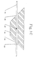
- the unistructural mass 21, shown in Figure 1B, is created when the memory polymer collapses around the glass fiber section which now forms a pin 23, guaranteeing precise alignment of both pin cavity 25 and open cavity 29.
- One functional advantage of this splice is in the separate operations of: alignment achieved by heating, and securing of fibers in an optimum position achieved by UV-curing of the index-matching adhesive.
- Another functional advantage is alignment of the optical fibers with respect to the aligning pin which is more precise than relying only on the inherent shape of a single cavity.
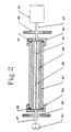
- This example describes a method of forming a cylindrical cavity in precise alignment with a cylindrical outer surface of the device by solidification of a resin on the surface of a spinning liquid which is immiscible with the liquid resin precursor and has a higher density.
- a liquid can be, for instance, water, a salt solution, molten inorganic salt, molten metal alloy, mercury and so forth.
- the apparatus for the spin casting is in Figure 2:
- Cylindrical vessel 41 is enclosed on one end by the lid 43 with the seal 45 and shaft 47 which is held by the bearing 49 and connected to the electrical motor 51.
- the similar lid 53 sealed by seal 55 is on the other end of the vessel 41.
- the lid 53 is equipped with hollow shaft 57 which is held by bearing 59 and ended by filling valve or enclosure 61.
- the vessel 41 is filled with precisely metered amounts of a suitable liquid (such as filtered mercury) and a liquid precursor to a crosslinked resin (such as the monomer mixture from Example 1).
- a suitable liquid such as filtered mercury
- a liquid precursor to a crosslinked resin such as the monomer mixture from Example 1.
- the fluid 67 can be a low-density liquid immiscible with the other components. More often, the fluid 67 is a gas.
- the volume of 67 increases as volume 65 shrinks due to the resin solidification (curing). The volume 67 can even be entirely due to the curing contraction.
- the curing of the resin under high-speed rotation forms a precisely concentric tube with dimensions which can be readily predicted from the vessel volume and diameter, amounts of liquid components and known volume contraction during the resin solidification.
- the precision tube is then deformed to increase its central cavity diameter.
- the tube is heated above the softening temperature of the resin, deformed by pressure of an inert fluid (ie. fluid which does not swell and/or plasticize the resin) inside of the cavity; and cooled to ambient temperature under pressure.
- an inert fluid ie. fluid which does not swell and/or plasticize the resin
- Cylindrical articles to be aligned can then be readily inserted into the enlarged cavity. If the device is heated above the softening temperature of the resin, the cavity collapses around the article aligning the article with respect to the outside surface of the device. The tube is then cooled to ambient temperature setting the resin into the glassy state to maintain and secure the aligned configuration.
- Example 2 The process according to Example 2 can be performed with a mixture of polymeric bis-epoxide and an aliphatic diamine which forms a sparingly crosslinked epoxy resin on the spinning mercury surface.
- the curing reaction is carried out above Ts of the cured resin so that conversion is practically complete at 125 deg. C after 24 hours.
- the volume shrinkage by crosslinking at this temperature is 0.17%.
- the amounts of the components are selected so that the final diameter of the resin tube is about 2.500 mm and the inner diameter 0.110 mm.
- the mold is cooled down and the rigid precision tubing is connected by both ends to a hydraulic pump containing glycerol.
- the tube is heated to abut 130 deg. C and glycerol pressure is increased to expand the inner cavity tubing to about 135 microns.
- the tube is cooled down while the pressure in the cavity is maintained.
- the tube is then cut to short sections (5 mm) and its ends are polished.
- the sections can be used as ferrules for connection of optical fibers.
- connection with the optical fiber is made as follows: Denuded end of an optical fiber (125 micron diameter) is inserted into the cavity so that the faces of the fiber and of the ferrule are in one plane. Then the tube is heated to about 135-150 deg. C for about thirty seconds and cooled down. The change of the outside diameter due to the fiber insertion is less than 1 micron.
- the final configuration is schematically depicted in Figure 3 where 71 is the unistructural cylindrical IMP body in which the precisely cylindrical outside surface 73 is precisely coaxial with the glass optical fiber 75. The advantages of this ferrule are low cost and simple installation without using adhesives.
- Monomer mixture is prepared by dissolution of 45 grams of low molecular weight copolymer of methylmethacrylate with 2 mol.% of allylmethacrylate (MW approximately 10,000) in a mixture of 50 grams of methyl methacrylate, 4.95 grams of ethyleneglycol dimethacrylate and 0.05 weight parts of benzoin. Molten mixture is then filled into the mold depicted in Fig. 4.
- the mold 81 is a polypropylene cylinder of inner diameter 15 mm which has lids 83,87 on each end. Core 85 of stainless steel rod of diameter 4.50 mm is inserted through the lids 83,87 so that it is coaxial with the mold wall and sealed.
- the mixture is then polymerized by UV lamp at ambient temperature first until vitrification, and then 6 hours at 125 deg. C.
- the cooled plastic molding is then lathed using the stainless steel core as the shaft until concentricity is achieved. Then the polymer is carefully swollen in Ethoxy Ethyl Acetate to an inner diameter of about 6 mm and pulled over a slightly conical TEFLON mandrel (6.6x5.5 mm for 250 mm of length). The acetate is gradually extracted with methanol and dried at 110 deg. C.
- the TEFLON mandrel is removed and the tubular device is used as a precision connecting element for various cylindrical articles of outside diameters between about 4.7 mm and 5.5 mm.
- articles to be connected and/or aligned are, for instance, shafts of electrical motors, to be connected with shafts of water pumps and other devices, tubings and capillaries, and so on.
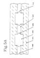
- Fig. 5A shows part of the mold assembly where 101 is the mold wall, 103 is the primary mandrel with lens-shaped rims 105, and spaces 107, 109 and 111 are filled with monomer mixture.
- the polymer sheet is removed from the mold and swollen in methanol-acetone mixtures with gradually increasing acetone concentration, until the lens-shaped inserts can be readily removed and replaced with similarly shaped inserts but with the diameter increased by about 10%.
- the polymer is then gradually deswollen and dried. The drying is finished at about 110 deg. C.
- the polymer becomes rigid and uniformly glassy as all its polymer components have a glass transition temperature around 100 deg. C or higher.
- the profile of the polymer in its rigid deformed state is in FIG. 5B where 121 is the memory polymer and 123 is the secondary mandrel.
- the Memory polymer thus formed is stronger, harder and more impact resistant than polymethylmethacrylate or similar purely amorphous resins due to a minor portion of crystalline network of polyacrylonitrile type which acts as additional physical network and reinforcing component.
- the crystals of PAN-type are not meltable below decomposition temperature (theoretical melting point of PAN is higher than 320 deg. C while depolymerization and degradation of this polymer starts at about 200 deg. C).
- Part of the polymer material is then milled off to make the shape of spectacle frames with two secondary mandrels per frame; the secondary mandrels are then removed.
- the frames are now ready for receiving lenses and for final custom shaping. If the glass lenses are now inserted into the deformed sockets and heated to a temperature between about 100 (where the material becomes deformable under internal stresses, albeit the shape recovery is slow) and about 200 deg. C (where the polymer decomposition starts), the lenses are secured into their mutually aligned positions.
- the shape of the frame can be adjusted to the individual needs by a gentle shaping at temperatures above 100 deg. C.
- This example describes a device and method for the connection and precision alignment of optical fiber with a passive or active optical device including but not limited to optical sources (such as LEDs or laser diodes), optical detectors, couplers, wavelength-division multiplexers, and switches which are customarily "pig-tailed".
- optical sources such as LEDs or laser diodes
- optical detectors such as LEDs or laser diodes
- couplers such as lasers or laser diodes
- wavelength-division multiplexers such as a passive or active optical device
- switches which are customarily "pig-tailed”.
- "Pig-tailing” provides the device with a short length of optical fiber of which one end is fixed by an epoxy adhesive to the "face” of the device while the other is prepared for connection to another optical fiber by splicing, connectorizing, fusion etc.
- sophisticated X-Y-Z translation stages are used to align a fiber end with the active area of the optical device in order to epoxy the fiber to the device.
- the installation procedure can be described by the following steps:
- the device can then be optionally heated to a temperature of 50 to 100 deg. to improve and finish the epoxy curing. However, this is generally not necessary, because the adhesive cure continues even at ambient temperature albeit at a slower rate.
- This device and method saves considerable installation time and eliminates the need for costly devices such as aligning X-Y-Z translators or mechanical splices. It also eliminates one connection thereby decreasing losses and making for a very compact, light-weight assembly.
- This example describes one combination of measures according to our invention to achieve precise alignment and mutual positioning of optical elements useful for both light and charged-particle optics.
- the goal is to demonstrate the possibility of combining high precision, speed of assembly and operation, and durability using a simple and inexpensive device.
- we are using this Example to illustrate the option of suppressing the Ts of IMP by plastification by monomers which are polymerized in a subsequent step after the alignment has been achieved.
- the mold is assembled in the following way:
- the polymer is now plasticized by the monomers introduced during the swelling step so that its softening temperature is depressed to about 50 deg. C.
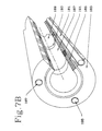
- the plasticized multilumen tube as depicted by 183 in Figure 7B, can be used for alignment and assembly of the elements of an electron gun in the following manner:
Landscapes
- Physics & Mathematics (AREA)
- General Physics & Mathematics (AREA)
- Optics & Photonics (AREA)
- Shaping By String And By Release Of Stress In Plastics And The Like (AREA)
- Mechanical Coupling Of Light Guides (AREA)
- Light Guides In General And Applications Therefor (AREA)
- Compositions Of Macromolecular Compounds (AREA)
Applications Claiming Priority (2)
| Application Number | Priority Date | Filing Date | Title |
|---|---|---|---|
| US464187 | 1990-01-12 | ||
| US07/464,187 US5037178A (en) | 1988-12-22 | 1990-01-12 | Amorphous memory polymer alignment device |
Publications (2)
| Publication Number | Publication Date |
|---|---|
| EP0439892A2 true EP0439892A2 (de) | 1991-08-07 |
| EP0439892A3 EP0439892A3 (en) | 1991-11-13 |
Family
ID=23842901
Family Applications (1)
| Application Number | Title | Priority Date | Filing Date |
|---|---|---|---|
| EP19900304651 Withdrawn EP0439892A3 (en) | 1990-01-12 | 1990-04-27 | Amorphous memory polymer alignment device |
Country Status (4)
| Country | Link |
|---|---|
| US (1) | US5037178A (de) |
| EP (1) | EP0439892A3 (de) |
| JP (1) | JPH03214110A (de) |
| CA (1) | CA2015529A1 (de) |
Cited By (6)
| Publication number | Priority date | Publication date | Assignee | Title |
|---|---|---|---|---|
| EP1217403A1 (de) * | 2000-12-22 | 2002-06-26 | Lucent Technologies Inc. | Optischer Verbinder mit Formgedächtnis-Polymer |
| US7455674B2 (en) | 2002-01-31 | 2008-11-25 | Smith & Nephew Plc | High strength bioresorbables containing poly-glycolic acid |
| US7524891B2 (en) | 2001-07-04 | 2009-04-28 | Smith & Nephew Plc | Biodegradable polymer systems |
| US9120919B2 (en) | 2003-12-23 | 2015-09-01 | Smith & Nephew, Inc. | Tunable segmented polyacetal |
| US9770534B2 (en) | 2007-04-19 | 2017-09-26 | Smith & Nephew, Inc. | Graft fixation |
| US9815240B2 (en) | 2007-04-18 | 2017-11-14 | Smith & Nephew, Inc. | Expansion moulding of shape memory polymers |
Families Citing this family (22)
| Publication number | Priority date | Publication date | Assignee | Title |
|---|---|---|---|---|
| JPH02121907A (ja) * | 1988-10-31 | 1990-05-09 | Mitsubishi Heavy Ind Ltd | 人用化粧料 |
| US5370109A (en) * | 1993-02-19 | 1994-12-06 | United States Surgical Corporation | Deformable endoscopic surgical retractor |
| US5450842A (en) * | 1993-02-19 | 1995-09-19 | United States Surgical Corporation | Endoscopic surgical retractor |
| US5445140A (en) * | 1993-06-07 | 1995-08-29 | United States Surgical Corporation | Endoscopic surgical device |
| US6240630B1 (en) * | 1997-12-03 | 2001-06-05 | The Regents Of The University Of California | Apparatus for loading shape memory gripper mechanisms |
| US6679605B2 (en) * | 2000-05-22 | 2004-01-20 | Medennium, Inc. | Crystalline polymeric compositions for ophthalmic devices |
| US7207946B2 (en) * | 2002-05-09 | 2007-04-24 | Spiration, Inc. | Automated provision of information related to air evacuation from a chest cavity |
| US6944920B2 (en) * | 2002-10-19 | 2005-09-20 | General Motors Corporation | Electrostatically releasable fastening system and method of use |
| US7308738B2 (en) | 2002-10-19 | 2007-12-18 | General Motors Corporation | Releasable fastener systems and processes |
| JP4015983B2 (ja) * | 2002-10-19 | 2007-11-28 | ゼネラル・モーターズ・コーポレーション | 解除可能な付属品用の磁気粘性ナノ複合エラストマー |
| US7013536B2 (en) * | 2002-10-19 | 2006-03-21 | General Motors Corporation | Releasable fastener systems and processes |
| US7146690B2 (en) * | 2002-10-19 | 2006-12-12 | General Motors Corporation | Releasable fastener system |
| US7140081B2 (en) * | 2002-10-19 | 2006-11-28 | General Motors Corporation | Releasable fastener system |
| US7032282B2 (en) | 2002-10-19 | 2006-04-25 | General Motors Corporation | Releasable fastener system |
| US6983517B2 (en) * | 2002-10-19 | 2006-01-10 | General Motors Corporation | Releasable fastener system |
| US6973701B2 (en) * | 2002-10-19 | 2005-12-13 | General Motors Corporation | Releasable fastening system based on ionic polymer metal composites and method of use |
| US7013538B2 (en) | 2002-10-19 | 2006-03-21 | General Motors Corporation | Electroactive polymer releasable fastening system and method of use |
| US6920675B2 (en) * | 2003-07-01 | 2005-07-26 | General Motors Corporation | Process for attachment and/or disengagement of components |
| CA2446533A1 (en) * | 2003-10-24 | 2005-04-24 | 9134-9001 Quebec Inc. | Flexible ferrule device for connection of optical fiber and use thereof |
| US20060261109A1 (en) * | 2005-05-18 | 2006-11-23 | Browne Alan L | Cargo container including an active material based releasable fastener system |
| US8722783B2 (en) | 2006-11-30 | 2014-05-13 | Smith & Nephew, Inc. | Fiber reinforced composite material |
| JP5520814B2 (ja) | 2007-04-19 | 2014-06-11 | スミス アンド ネフュー インコーポレーテッド | マルチモーダル形状記憶ポリマー |
Family Cites Families (24)
| Publication number | Priority date | Publication date | Assignee | Title |
|---|---|---|---|---|
| GB865378A (en) * | 1956-08-30 | 1961-04-19 | Ti Group Services Ltd | Improvements in and relating to chlorinated polymers |
| NL130678C (de) * | 1960-07-15 | 1900-01-01 | ||
| NL270833A (de) * | 1960-10-31 | |||
| US3370112A (en) * | 1963-09-26 | 1968-02-20 | Raychem Corp | Process and apparatus for producing plastic memory articles |
| US3616363A (en) * | 1968-05-17 | 1971-10-26 | Du Pont | Photolytic cross-linking of olefinic hydrocarbon containing carboxylic acid copolymers |
| US4193899A (en) * | 1977-11-29 | 1980-03-18 | Exxon Research & Engineering Co. | Elastomeric systems having unusual memory characteristics |
| US4178067A (en) * | 1978-01-19 | 1979-12-11 | Amp Incorporated | Splicing optic waveguides by shrinkable means |
| US4179320A (en) * | 1978-04-10 | 1979-12-18 | Raychem Corporation | Recoverable articles |
| US4261644A (en) * | 1978-11-30 | 1981-04-14 | The United States Of America As Represented By The Secretary Of The Navy | Method and article of manufacturing an optical fiber connector |
| US4396476A (en) * | 1979-02-01 | 1983-08-02 | Dentsply Research & Development Corporation | Blend of cross-linked polymer, swelling monomer and cross-linking agent and curing process |
| US4352542A (en) * | 1980-08-26 | 1982-10-05 | The United States Of America As Represented By The Secretary Of The Navy | Cable connector |
| CA1217310A (en) * | 1981-09-14 | 1987-02-03 | George B. Park | Heat recoverable article |
| US4467002A (en) * | 1981-12-15 | 1984-08-21 | Raychem Limited | Dimensionally-recoverable article |
| SE429626B (sv) * | 1982-01-20 | 1983-09-19 | Tetra Pak Dev | Sett att medelst krympformning framstella forpackningsbehallare jemte anordning for settets utforande |
| US4489217A (en) * | 1982-04-07 | 1984-12-18 | Raychem Corporation | Shield connection device |
| CA1179211A (en) * | 1982-11-12 | 1984-12-11 | Dilip K. Tailor | Heat shrinkable covering and method for applying same |
| EP0105775B1 (de) * | 1982-09-20 | 1989-01-11 | Norsolor S.A. | Schrumpffähige geformte Gegenstände |
| ATE40011T1 (de) * | 1982-11-26 | 1989-01-15 | British Telecomm | Verbindungsstuecke. |
| US4725117A (en) * | 1984-11-13 | 1988-02-16 | Raychem Corporation | Optical fiber contact and method of terminating an optical fiber using same |
| GB2172540B (en) * | 1985-03-18 | 1988-12-21 | Metal Box Plc | Making dimensionally stable thermoplastic open-ended tubular articles |
| GB8512699D0 (en) * | 1985-05-20 | 1985-06-26 | Raychem Ltd | Article comprising fibre |
| FR2601285B1 (fr) * | 1986-07-10 | 1988-11-04 | Pirelli Treficable | Manchon thermoretractable comportant des moyens pour controler son chauffage uniforme, et procede de fabrication de ce manchon. |
| GB8619398D0 (en) * | 1986-08-08 | 1986-09-17 | Raychem Ltd | Dimensionally recoverable article |
| US4921323A (en) * | 1988-12-22 | 1990-05-01 | Kingston Technologies, L.P. | Memory polymer optical fiber splicer and methods |
-
1990
- 1990-01-12 US US07/464,187 patent/US5037178A/en not_active Expired - Fee Related
- 1990-04-26 CA CA002015529A patent/CA2015529A1/en not_active Abandoned
- 1990-04-27 JP JP2110694A patent/JPH03214110A/ja active Pending
- 1990-04-27 EP EP19900304651 patent/EP0439892A3/en not_active Withdrawn
Cited By (6)
| Publication number | Priority date | Publication date | Assignee | Title |
|---|---|---|---|---|
| EP1217403A1 (de) * | 2000-12-22 | 2002-06-26 | Lucent Technologies Inc. | Optischer Verbinder mit Formgedächtnis-Polymer |
| US7524891B2 (en) | 2001-07-04 | 2009-04-28 | Smith & Nephew Plc | Biodegradable polymer systems |
| US7455674B2 (en) | 2002-01-31 | 2008-11-25 | Smith & Nephew Plc | High strength bioresorbables containing poly-glycolic acid |
| US9120919B2 (en) | 2003-12-23 | 2015-09-01 | Smith & Nephew, Inc. | Tunable segmented polyacetal |
| US9815240B2 (en) | 2007-04-18 | 2017-11-14 | Smith & Nephew, Inc. | Expansion moulding of shape memory polymers |
| US9770534B2 (en) | 2007-04-19 | 2017-09-26 | Smith & Nephew, Inc. | Graft fixation |
Also Published As
| Publication number | Publication date |
|---|---|
| CA2015529A1 (en) | 1991-07-12 |
| EP0439892A3 (en) | 1991-11-13 |
| US5037178A (en) | 1991-08-06 |
| JPH03214110A (ja) | 1991-09-19 |
Similar Documents
| Publication | Publication Date | Title |
|---|---|---|
| US5037178A (en) | Amorphous memory polymer alignment device | |
| US5066091A (en) | Amorphous memory polymer alignment device with access means | |
| US4969705A (en) | Memory polymer multiple cavity fiber splicer | |
| SU674658A3 (ru) | Форма дл изготовлени контактных линз | |
| US4921323A (en) | Memory polymer optical fiber splicer and methods | |
| US5587116A (en) | Process for injection molding optical ferrules | |
| JPH063545A (ja) | 光伝走路ネットワーク用デバイスの製造方法およびこの方法により製造したデバイス | |
| EP1494847B1 (de) | Verfahren zur herstellung von einer mikrostrukturierten optischen faser | |
| US6074511A (en) | Method of joining plastic optical fibers to each other | |
| JP2002228880A (ja) | 第1のエレメントを第2のエレメントに結合するための方法およびポリマーコネクタの製造方法 | |
| JPH1176279A (ja) | 眼内レンズの製造方法 | |
| EP0237995B1 (de) | Wärmeresistente optische Faser aus Kunstharz | |
| Heckele et al. | Hot embossing and injection molding for micro-optical components | |
| KR20030090818A (ko) | 플라스틱 광섬유 모재 및 이의 제조방법 | |
| Kalveram et al. | Precision molding techniques for optical waveguide devices | |
| Johnson et al. | Precision molded plastic ferrules for single-mode optical fibers | |
| Schulze et al. | Contactless embossing of microlenses: a new technology for manufacturing refractive microlenses | |
| US11745454B2 (en) | High resolution and high flexibility fiber optical cables and microfabrication methods for making same | |
| Bauer et al. | Manufacturing microcomponents for optical information technology using the LIGA technique | |
| JPH0854520A (ja) | プラスチック光ファイバ母材の製造方法 | |
| JPH03221905A (ja) | プラスチック光導波路、その製法およびそれを用いた光部品 | |
| JPH10319252A (ja) | プラスチック光ファイバ母材の製造方法 | |
| Wu | Overview of MEMS technology for packaging optoelectronic components | |
| Bauer et al. | Micro-optical Components for Information Technology fabricated via LIGA Technique | |
| Lai et al. | Polymer microlens array integrated with imaging sensors by UV-molding technique |
Legal Events
| Date | Code | Title | Description |
|---|---|---|---|
| PUAI | Public reference made under article 153(3) epc to a published international application that has entered the european phase |
Free format text: ORIGINAL CODE: 0009012 |
|
| AK | Designated contracting states |
Kind code of ref document: A2 Designated state(s): BE DE FR GB LU NL |
|
| PUAL | Search report despatched |
Free format text: ORIGINAL CODE: 0009013 |
|
| AK | Designated contracting states |
Kind code of ref document: A3 Designated state(s): BE DE FR GB LU NL |
|
| 17P | Request for examination filed |
Effective date: 19920511 |
|
| 17Q | First examination report despatched |
Effective date: 19930504 |
|
| STAA | Information on the status of an ep patent application or granted ep patent |
Free format text: STATUS: THE APPLICATION IS DEEMED TO BE WITHDRAWN |
|
| 18D | Application deemed to be withdrawn |
Effective date: 19930915 |