EP0438740A1 - Fitting for a wing of a window, door or similar which at least pivots - Google Patents
Fitting for a wing of a window, door or similar which at least pivots Download PDFInfo
- Publication number
- EP0438740A1 EP0438740A1 EP90124811A EP90124811A EP0438740A1 EP 0438740 A1 EP0438740 A1 EP 0438740A1 EP 90124811 A EP90124811 A EP 90124811A EP 90124811 A EP90124811 A EP 90124811A EP 0438740 A1 EP0438740 A1 EP 0438740A1
- Authority
- EP
- European Patent Office
- Prior art keywords
- wing
- bearing
- bearing part
- fitting according
- fitting
- Prior art date
- Legal status (The legal status is an assumption and is not a legal conclusion. Google has not performed a legal analysis and makes no representation as to the accuracy of the status listed.)
- Withdrawn
Links
Images

Classifications
-
- E—FIXED CONSTRUCTIONS
- E05—LOCKS; KEYS; WINDOW OR DOOR FITTINGS; SAFES
- E05D—HINGES OR SUSPENSION DEVICES FOR DOORS, WINDOWS OR WINGS
- E05D15/00—Suspension arrangements for wings
- E05D15/48—Suspension arrangements for wings allowing alternative movements
- E05D15/52—Suspension arrangements for wings allowing alternative movements for opening about a vertical as well as a horizontal axis
- E05D15/5211—Concealed suspension fittings
-
- E—FIXED CONSTRUCTIONS
- E05—LOCKS; KEYS; WINDOW OR DOOR FITTINGS; SAFES
- E05D—HINGES OR SUSPENSION DEVICES FOR DOORS, WINDOWS OR WINGS
- E05D7/00—Hinges or pivots of special construction
- E05D7/08—Hinges or pivots of special construction for use in suspensions comprising two spigots placed at opposite edges of the wing, especially at the top and the bottom, e.g. trunnions
- E05D7/081—Hinges or pivots of special construction for use in suspensions comprising two spigots placed at opposite edges of the wing, especially at the top and the bottom, e.g. trunnions the pivot axis of the wing being situated near one edge of the wing, especially at the top and bottom, e.g. trunnions
-
- E—FIXED CONSTRUCTIONS
- E05—LOCKS; KEYS; WINDOW OR DOOR FITTINGS; SAFES
- E05D—HINGES OR SUSPENSION DEVICES FOR DOORS, WINDOWS OR WINGS
- E05D7/00—Hinges or pivots of special construction
- E05D7/04—Hinges adjustable relative to the wing or the frame
- E05D2007/0469—Hinges adjustable relative to the wing or the frame in an axial direction
-
- E—FIXED CONSTRUCTIONS
- E05—LOCKS; KEYS; WINDOW OR DOOR FITTINGS; SAFES
- E05Y—INDEXING SCHEME RELATING TO HINGES OR OTHER SUSPENSION DEVICES FOR DOORS, WINDOWS OR WINGS AND DEVICES FOR MOVING WINGS INTO OPEN OR CLOSED POSITION, CHECKS FOR WINGS AND WING FITTINGS NOT OTHERWISE PROVIDED FOR, CONCERNED WITH THE FUNCTIONING OF THE WING
- E05Y2900/00—Application of doors, windows, wings or fittings thereof
- E05Y2900/10—Application of doors, windows, wings or fittings thereof for buildings or parts thereof
- E05Y2900/13—Application of doors, windows, wings or fittings thereof for buildings or parts thereof characterised by the type of wing
- E05Y2900/148—Windows
Definitions
- the invention relates to a fitting for an at least rotatable wing of a window, a door or the like, each with a pivot bearing for the lower and upper pivot axis corner of the wing and a circumferential, against a rebate space between the wing and a fixed frame open fitting groove.
- the sash is not only at least rotatably mounted on the fixed frame, but is locked in the closed position against the fixed frame.
- it is equipped with an operating handle which is connected to a gear or similar device.
- One or two with This gear connected drive rods carry locking members that cooperate with fixed frame-side locking counter-members, such as striking plates. If the wing is a turn-tilt wing, a so-called three-position gear is generally used as the gear.
- the fitting is designed according to the preamble of claim 1 in accordance with the characterizing part of this claim. Because the cross-section of the fitting part groove is defined in the sense of standardization, and the rebate space between sash and fixed frame cannot exceed a certain size, there is not enough space available for the installation of a concealed fitting in the area of the fitting part groove, at least not for one fitting , which can also be used with larger and heavier sashes, especially double-glazed sashes.
- the bearing pin of the lower frame bearing part is spherical at its free end or carries a ball and there is an internally spherical bearing bore or bearing socket on the wing bearing part.
- This bearing is especially suitable for a turn and tilt sash. It is then expedient if there is a spherical bearing pan or bearing recess conically expanding outer part.
Abstract
Description
Die Erfindung bezieht sich auf einen Beschlag für einen wenigstens drehbaren Flügel eines Fensters, einer Tür od. dgl., mit je einem Drehlager für die untere und obere drehachsseitige Ecke des Flügels sowie einer umlaufenden, gegen einen Falzraum zwischen dem Flügel und einem festen Rahmen hin offenen Beschlagteilnut. Mit Hilfe dieses Beschlags wird der Flügel am festen Rahmen nicht nur wenigstens drehbar gelagert, sondern in der Schließstellung gegen den festen Rahmen verriegelt. Zu diesem Zwecke ist er mit einem Bedienungsgriff ausgestattet, der mit einem Getriebe oder einer ähnlichen Einrichtung verbunden ist. Eine oder zwei mit diesem Getriebe verbundene Treibstangen tragen Verriegelungsglieder, die mit festrahmenseitigen Verriegelungs-Gegengliedern, beispielsweise Schließblechen, zusammenwirken. Falls es sich bei dem Flügel um einen Dreh-Kipp-Flügel handelt, so verwendet man in der Regel als Getriebe ein sogenanntes Drei-Stellungs-Getriebe.The invention relates to a fitting for an at least rotatable wing of a window, a door or the like, each with a pivot bearing for the lower and upper pivot axis corner of the wing and a circumferential, against a rebate space between the wing and a fixed frame open fitting groove. With the help of this fitting, the sash is not only at least rotatably mounted on the fixed frame, but is locked in the closed position against the fixed frame. For this purpose it is equipped with an operating handle which is connected to a gear or similar device. One or two with This gear connected drive rods carry locking members that cooperate with fixed frame-side locking counter-members, such as striking plates. If the wing is a turn-tilt wing, a so-called three-position gear is generally used as the gear.
Der Bedienungsgriff befindet sich üblicherweise am schließseitigen Vertikalholm des Flügels. Er muß immer gut zugänglich sein und deshalb steht er über die Innenfläche des Flügels vor. Es besteht vielfach der Wunsch, daß außer dem Bedienungsgriff kein Teil des Beschlags über die Innenfläche der Rahmen vorsteht und möglichst auch nicht sichtbar ist. Man bezeichnet derartige, im Prinzip bekannte Beschläge, als verdeckte Beschläge.The operating handle is usually located on the closing vertical spar of the wing. It must always be easily accessible and therefore it protrudes over the inside surface of the wing. There is often a desire that, apart from the operating handle, no part of the fitting protrudes beyond the inner surface of the frame and, if possible, is not visible. Such fittings, known in principle, are referred to as concealed fittings.
Die DE-PS 15 59 878 zeigt und beschreibt einen derartigen verdeckten Beschlag für ein Drehkippfenster. Er ist in bevorzugter Weise für Aluminium-Fenster ausgebildet, bei dem die Drehpunkte für die Kipp- und die Drehstellung hinter der Flügelvorderkante angeordnet sind. Dabei sind die Profilkonstruktion und der Beschlag selbst aufeinander abgestimmt. Für Fenster mit Standardfälzen, wie sie bei Konstruktionen aus Holz- oder Kunststoffprofilen vorgesehen sind, ist dieser Beschlag nicht verwendbar.DE-PS 15 59 878 shows and describes such a hidden fitting for a tilt and turn window. It is preferably designed for aluminum windows in which the pivot points for the tilt and the pivot position are arranged behind the leading edge of the sash. The profile construction and the fitting itself are coordinated. This fitting cannot be used for windows with standard rebates, such as those provided for constructions made of wood or plastic profiles.
Die Aufgabe der Erfindung besteht infolgedessen darin, einen Beschlag der eingangs genannten Art so weiterzubilden, daß er auch in ein Fenster oder in eine Tür mit sogenannten Standardfälzen oder ähnlich profilierten Rahmenholmen eingebaut werden kann, die über eine umlaufende, gegebenenfalls auch eine sich lediglich über drei Holme erstreckende Beschlagteilnut für den üblichen Verschluß verfügen.The object of the invention is therefore to develop a fitting of the type mentioned in such a way that it also in a window or in a door with so-called standard rebates or similarly profiled frame spars can be installed, which have a circumferential, possibly also only a three spar extending fitting part groove for the usual closure.
Zur Lösung dieser Aufgabe wird erfindungsgemäß vorgeschlagen, daß der Beschlag gemäß dem Oberbegriff des Anspruchs 1 entsprechend dem kennzeichnenden Teil dieses Anspruchs ausgebildet ist. Weil der Querschnitt der Beschlagteilnut im Sinne einer Normung festgelegt ist, und auch der Falzraum zwischen Flügel und festem Rahmen eine bestimmte Größe nicht überschreiten kann, steht für den Einbau eines verdeckten Beschlags im Bereich der Beschlagteilnut kein ausreichender Platz zur Verfügung, zumindest nicht für einen Beschlag, der auch bei größeren und schwereren Flügeln, insbesondere doppelt verglasten Flügeln, verwendet werden kann. Wenn man nun aber erfindungsgemäß neben dem drehachsseitigen Teil der Beschlagteilnut zumindest am unteren Drehlager eine Aufnahme vorsieht, die quer zur geometrischen Drehachse unmittelbar in den vertikalen Teil der Beschlagteilnut übergeht, so kann man darin einen seitlichen Ansatz des betreffenden Flügellagerteils unterbringen. Dieser Ansatz, den man auch als seitliche Verbreiterung des Gehäuses oder Grundkörpers des Flügellagerteils ansehen kann, ermöglicht insgesamt eine sehr kräftige und damit auch entsprechend belastbare Ausbildung des Flügellagerteils, so daß dieses Flügellager auch für große und schwere Flügel geeignet ist. Wenn man den Querschnitt der Aufnahme günstig wählt, so ist deren Anbringung, beispielsweise bei einem Holzrahmen, völlig problemlos und sie kann auch so ausgeführt werden, daß die dadurch verursachte Schwächung des Rahmenquerschnitts so gering wie möglich gehalten werden kann. Andererseits ist dieser Beschlag für eine Serienfertigung geeignet und sein besonderer Vorteil liegt darin, daß er zumindest weitgehend die Verwendung mit einem herkömmlichen Verschluß und anderen Beschlagteilen einer Standardkonstruktion ermöglicht. Nicht nur die beiden, zumindest das Drehen des Flügels ermöglichenden Lager, sondern auch die übrigen Teile eines Standardbeschlags können innerhalb des Rahmens untergebracht werden. Auch die Nuten brauchen von den Standardnuten nicht abzuweichen, so daß im Falle eines Holzrahmens die üblichen und in der Regel bei einem Fensterbauer immer vorhandenen Fräsersätze und dergleichen weiterhin verwendet werden können. Die Rahmen können in herkömmlicher oder davon etwas abweichender Weise gefälzt sein. Außerdem ist die Anbringung eines sogenannten Beifalzes am festen Rahmen möglich. Er macht das Anbringen einzelner Fräsungen für die Schließplatten eines Standardbeschlags überflüssig, ohne das optische Erscheinungsbild des Fensters oder der Tür negativ zu beeinträchtigen. Selbstverständlich behindert dieser Beschlag auch nicht die Anbringung einer besonderen Dichtung zwischen dem festen Rahmen und dem Blendrahmen.To achieve this object, it is proposed according to the invention that the fitting is designed according to the preamble of
Eine Weiterbildung der Erfindung ergibt sich aus Anspruch 2. Die Verwendung eines kreisförmigen Querschnitts für die Aufnahme hat den Vorteil, daß letztere mit Hilfe eines entsprechenden Bohrers oder Fräsers leicht erstellt werden kann. Weil jedoch der seitliche Ansatz und das Gehäuse oder der Grundkörper des Flügellagerteils eine Einheit bilden, sie insbesondere einstückig hergestellt sind, gehen nicht nur diese beiden Teile mit einer entsprechenden Breite unmittelbar ineinander über, sondern auch die Aufnahme und der vertikale Teil der Beschlagteilnut. Die Zuordnung kann so getroffen werden, daß die eine Flanke der Beschlagteilnut etwa eine Sehne des Kreisquerschnitts bildet. Da die Aufnahme nicht nur in Querrichtung gegen die Beschlagteilnut hin offen ist, sondern auch in axialer Richtung nach oben bzw. nach unten, kann man von oben her bzw. von unten her das Flügellagerteil in die Aufnahme und die Beschlagteilnut einschieben. Die Montageendlage kann man leicht dadurch vorgeben, daß man die Aufnahme in Achsrichtung gesehen, genau herstellt. Wie bei bekannten Dreh- oder Dreh-Kipp-Lagern kann man den Lagerzapfen am Rahmenlagerteil und die Lagerbohrung am Flügellagerteil oder umgekehrt anbringen.A further development of the invention results from
Eine weitere Ausgestaltung der Erfindung sieht vor, daß der Lagerzapfen des unteren Rahmenlagerteils an seinem freien Ende ballig ausgebildet ist oder eine Kugel trägt und sich am Flügellagerteil eine innen kugelig ausgeformte Lagerbohrung oder Lagerpfanne befindet. Dieses Lager ist vor allen Dingen für einen Dreh-Kipp-Flügel geeignet. Dabei ist es dann zweckmäßig, wenn sich an die kugelige Lagerpfanne oder Lagerausnehmung ein sich konisch erweiternder Außenteil anschießt.Another embodiment of the invention provides that the bearing pin of the lower frame bearing part is spherical at its free end or carries a ball and there is an internally spherical bearing bore or bearing socket on the wing bearing part. This bearing is especially suitable for a turn and tilt sash. It is then expedient if there is a spherical bearing pan or bearing recess conically expanding outer part.
Eine besonders bevorzugte Ausführungsform der Erfindung kennzeichnet sich dadurch, daß der Lagerzapfen des oberen Flügellagerteils in das Innere seines seitlichen Ansatzes verschiebbar oder aus diesem ausschiebbar ist. Eine besondere Bedeutung kommt diesem Merkmal bei einem oberen Drehlager zu. Es erleichtert das Ein- und Aushängen des Flügels, indem man zum Aushängen den Lagerzapfen ins Innere des Flügellagers zumindest soweit verschiebt, daß er aus der Lagerbohrung des Festrahmenteils austritt.A particularly preferred embodiment of the invention is characterized in that the bearing journal of the upper wing bearing part can be moved into the interior of its lateral extension or can be pushed out of it. This feature is particularly important for an upper pivot bearing. It makes it easier to mount and unmount the sash by moving the bearing journal inside the sash bearing at least to the extent that it emerges from the bearing bore in the fixed frame part.
Eine weitere Variante der Erfindung ist dadurch gekennzeichnet, daß der Grundkörper oder das Gehäuse des oberen und unteren Flügellagerteils eine im wesentlichen winkelförmige Gestalt aufweist, wobei die Winkelschenkel dem Querschnitt in der Beschlagteilnut angepaßt und darin wenigstens teilweise eingesetzt sind. Wenn es sich bei der Beschlagteilnut um eine Standardnut handelt, die an ihrem äußeren Ende zum Anlegen einer Stulpschiene absatzweise verbreitert ist, so kann man dies durch entsprechende Ausbildung des Flügellagerteil-Grundkörpers berücksichtigen. Ansonsten wird der Grundkörper möglichst vollständig in die Beschlagteilnut eingesetzt und darin in geeigneter und bekannter Weise verankert, beispielsweise angeschraubt. Aus diesem Grunde wird man den Grundkörper an geeigneter Stelle mit wenigstens einem, vorzugsweise aber mit mehreren Befestigungsdurchbrüchen bzw. Bohrungen ausstatten.Another variant of the invention is characterized in that the base body or the housing of the upper and lower wing bearing part has an essentially angular shape, the angle legs being adapted to the cross section in the fitting part groove and being at least partially inserted therein. If the fitting part groove is a standard groove that is widened in sections at its outer end for fitting a faceplate, this can be taken into account by appropriate design of the wing bearing part base body. Otherwise, the base body is inserted as completely as possible into the fitting part groove and anchored therein in a suitable and known manner, for example screwed on. For this reason, the base body will be equipped at a suitable point with at least one, but preferably with several fastening openings or bores.
In Weiterbildung der Erfindung wird vorgeschlagen, daß das Flügellagerteil zumindest des unteren Ecklagers zweiteilig ausgebildet ist und die beiden Teile parallel zur Drehachse gegeneinander verstellbar sind. Mit Hilfe dieses Flügellagerteils kann man leicht eine Höheneinstellung des Flügels gegenüber dem festen Rahmen durchführen. Wenn man das untere Ecklager derart einstellbar ausbildet, so erübrigt sich eine dementsprechende Konstruktion am oberen Ecklager, vielmehr kann man hierfür eine einfachere und damit kostengünstigere Ausbildung vorsehen. Die Verstellung erfolgt in bekannter Weise über ein zwischengeschaltetes Schraubglied.In a development of the invention it is proposed that the wing bearing part of at least the lower corner bearing is formed in two parts and the two parts are mutually adjustable parallel to the axis of rotation. With the help of this wing bearing part you can easily adjust the height of the wing relative to the fixed frame. If the lower corner bearing is designed to be adjustable in this way, there is no need for a corresponding construction on the upper corner bearing, rather a simpler and therefore more cost-effective training can be provided for this. The adjustment is carried out in a known manner via an intermediate screw member.
Eine in dieser Hinsicht vorteilhafte Ausgestaltung der Erfindung ergibt sich aus Anspruch 13. Die äußeren Abmessungen der Winkelschenkel sind auch bei der zweiteiligen Ausführung durch die Beschlagteilnut vorgegeben. Soweit Teile ineinandergreifen, oder gegeneinander verschiebbar sind, muß dem durch die Dimensionierung des jeweils außenliegenden Teils entsprechend Rechnung getragen werden. Eng tolerierte Längsführungen gewährleisten auch bei der verstellbaren Ausführung eine stabile Lagerausbildung, die den Belastungen voll gewachsen ist, wobei es sich bekanntermaßen nicht nur um Gewichtsbelastungen handelt.An advantageous embodiment of the invention in this respect results from
Eine andere bevorzugte Ausführungsform der Erfindung ist in Anspruch 14 beschrieben. Herstellungsmäßig verlangt sie keinen besonderen Aufwand und bei der Montage erfordert sie keine speziellen Maßnahmen. Andererseits ist sie aber trotz ihrer einfachen Ausbildung sehr wirkungsvoll. Der Aushebesicherung kommt insbesondere im gekippten Zustand des Flügels besondere Bedeutung zu. Die Dimensionierung der beiden Teile der Aushebesicherung ist so vorzunehmen, daß die notwendigen Relativbewegungen sowohl bei der Montage, als auch bei der Benutzung des Flügels möglich sind. Weil diese Aushebesicherung in erster Linie für den gekippten Flügel gedacht ist, ist es aus Montagegründen zweckmäßig, wenn man das Einhängen des Flügels in der Drehstellung des Beschlags vornimmt. Außerdem muß diese Aushebesicherung das Drehen des Flügels ohne weiteres ermöglichen.Another preferred embodiment of the invention is described in
Das Rahmenlagerteil ist in besonders bevorzugter Weise zweiteilig ausgebildet, wobei seine beiden Teile in horiziontaler Richtung gegeneinander verstellbar sind. Damit läßt sich der Flügel quer zur geometrischen Drehachse bezüglich des festen Rahmen sehr genau ausrichten. Die Verstellung nimmt man am besten auch hier über ein Gewinde vor.In a particularly preferred manner, the frame bearing part is formed in two parts, its two parts being mutually adjustable in the horizontal direction. This allows the wing to be aligned very precisely transversely to the geometric axis of rotation with respect to the fixed frame. The best way to do this is to use a thread.
Eine weitere bevorzugte Variante der Erfindung enthält Anspruch 17. Im Normalfalle kommt ihr nur bei einem Dreh-Kipp-Flügel Bedeutung zu. Dabei fluchtet die geometrische Drehachse des unteren Drehlagers mit dem Drehlager der Ausstellvorrichtung. Weil letzteres aus Festigkeitsgründen eine die Höhe des Falzraums übersteigende Dicke aufweisen muß, bringt man auch in diesem Falle am oberen Flügelquerholm eine Aufnahme an, die derjenigen am unteren Flügelende entspricht und die damit koaxial angeordnet ist, jedoch reicht dabei eine geringere Tiefe aus. Auf jeden Fall können beide Bohrungen sowohl bei dieser Variante, als auch bei derjenigen mit einem normalen oberen Drehlager auf die gleiche Weise und unter Verwendung gleicher Werkzeuge und gegebenenfalls Bohrlehren und dgl. angebracht werden.A further preferred variant of the invention contains
Eine Weiterbildung der Erfindung ergibt sich aus Anspruch 18. Im Hinblick auf die gute Bedienbarkeit der Längeneinstellvorrichtung, aber auch wegen der einfachen Ausbildung und Montage, bietet sich die Verwendung eines Einstellexzenters in Verbindung mit einem Längsschlitz besonders an. Die jeweils gefundene Längeneinstellung, die ebenfalls der Ausrichtung des Flügels dient, kann in geeigneter und bekannter Weise, beispielsweise mittels einer Klemmschraube od. dgl., vorgenommen werden. Weitere vorteilhafte Ausgestaltungen dieses Beschlags und zusätzliche Vorteile ergeben sich aus der nachfolgenden Beschreibung zweier Ausführungsbeispiele. Die Zeichnung zeigt diese zwei Ausführungsbeispiele. Hierbei stellen dar:
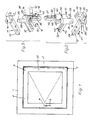
- Fig. 1
- eine Innenansicht eines mit dem Beschlag ausgestatteten Fensters mit einem Drehflügel,
- Fig. 2
- in vergrößertem Maßstab perspektivisch und explosionsartig das untere Drehlager,
- Fig. 3
- eine dementsprechende Darstellung des oberen Drehlagers,
- Fig. 4
- in einer gegenüber Fig. 1 verkleinerten Darstellung eine Innenansicht eines zweiten Fensters mit einem Dreh-Kipp-Flügel,
- Fig. 5
-
ein der Figur 2 entsprechendes unteres Dreh-Kipp-Lager, - Fig. 6
- ebenfalls in Schrägbilddarstellung und verkleinert eine Ausstellvorrichtung,
- Fig. 7
- einen vergrößerten horiziontalen Schnitt etwa an der Stelle VII-
VII der Figur 4.
- Fig. 1
- an interior view of a window equipped with the fitting with a rotating sash,
- Fig. 2
- on an enlarged scale, perspective and explosive, the lower pivot bearing,
- Fig. 3
- a corresponding representation of the upper pivot bearing,
- Fig. 4
- 1 is an interior view of a second window with a tilt and turn sash,
- Fig. 5
- a lower turn-tilt bearing corresponding to Figure 2,
- Fig. 6
- also in an oblique view and reduces the size of an opening device,
- Fig. 7
- an enlarged horizontal section approximately at the point VII-VII of Figure 4.
In einem festen Rahmen 1 ist ein Flügel 2 um eine vertikale Achse 3 drehbar gelagert. Mit Hilfe eines Getriebes 4 od. dgl. läßt sich wenigstens eine Treibstange 5 verschieben. Das Getriebe wird über eine Handhabe 6 betätigt. An der sich vom Getriebe 4 nach oben oder nach oben und unten erstreckenden Treibstange befinden sich nicht gezeigte, an sich bekannte Verriegelungsglieder, die bei geschlossenem Flügel mit entsprechenden Verriegelungsgegengliedern, beispielsweise Schließblechen od. dgl., zusammenwirken. Solche Verriegelungsstellen können sich sowohl an der Schließseite des Flügels, als auch an dessen oberem und/oder unterem Ende befinden. Bei dem lediglich drehbaren Flügel der Fig. 1 finden ein unteres Drehlager 7 und ein oberes Drehlager 8 Verwendung. Fig. 2 zeigt das erfindungsgemäß ausgebildete untere Drehlager, während sich das zugehörige obere Drehlager aus Fig. 3 ergibt.A
Das untere Drehlager 7 besteht seinerseits aus einem Rahmenlagerteil 9 und einem Flügellagerteil 10. In gleicher Weise besitzt das obere Drehlager 8 ein Rahmenlagerteil 11 und ein Flügellagerteil 12. Beim Ausführungsbeispiel sind die beiden Rahmenlagerteile 9 und 11 im wesentlichen gleich ausgebildet. Der einzige Unterschied besteht darin, daß am Rahmenlagerteil 9 ein Lagerzapfen 13 angebracht ist, während sich an entsprechender Stelle beim Rahmenlagerteil 11 eine Lagerbohrung 14 befindet.The lower pivot bearing 7 in turn consists of a
Das Rahmenlagerteil 9 bzw. 11 ist beim Ausführungsbeispiel und in bevorzugter Weise zweiteilig ausgebildet. Dabei wird das eine Teil 15 am zugeordneten horiziontalen Holm des festen Rahmens angeschlagen, insbesondere angeschraubt. Es besitzt zu diesem Zwecke zwei im Längsabstand angeordnete, angesenkte Befestigungsbohrungen 16 und 17. Es hat einen im wesentlichen U-förmigen Querschnitt, der im Bereich des Lagerzapfens 13 bzw. der Lagerbohrung 14 ausgenommen ist. Am freien Ende befindet sich ein stegartiger Winkelschenkel 18 mit einer Befestigungsbohrung 19 und einer Aufnahme 20. Das eine Teil 15 hat infolgedessen eine winkelförmige Gestalt. Das andere Teil 23 ist zwischen den U-Schenkeln des einen Teils 15 im Sinne des Doppelpfeils 21 verschiebbar gelagert. Es trägt den Lagerzapfen 13 bzw. die Lagerbohrung 14, und zwar an einem seitlichen Ansatz 22. Dieser ist der Stelle des einen Teils 15 zugeordnet, an dem der U-Schenkel fehlt.The
Zwischen die beiden Teile 15 und 23 des Rahmenlagerteils 9 bzw. 11 ist eine Verstellschraube 24 geschaltet. Mit deren Hilfe kann das Teil 23 gegenüber dem einen Lagerteil 15 feinfühlig verstellt werden, wobei dann der Lagerzapfen 13 parallel zu sich wandert. Die Verstellschraube 24 ist in einem der beiden Teile, beispielsweise im anderen Teil 23 drehbar aber unverschiebbar gelagert und sie durchsetzt ein Muttergewinde am in Fig. 2 linken Ende des einen Teils 15. Die Verstellschraube ist in bekannter Weise mit einer Aufnahme für ein Betätigungswerkzeug, beispielsweise einem Schlitz, versehen. An dieser Stelle wird noch darauf hingewiesen, daß der Lagerzapfen 13 beim Ausführungsbeispiel aus einem Schaft mit an dessen freiem Ende angebrachter Kugel 25 besteht. Aus diesem Grunde ist die zugehörige, als Sackbohrung ausgebildete Lagerbohrung 26 innen in der Art einer Hohlkugel gestaltet, an die sich nach außen hin eine trichterförmige Erweiterung anschließt, welche das Kippen ohne weiteres ermöglicht.An adjusting
Das Flügellagerteil 10, 12 besitzt im wesentlichen eine winkelförmige Gestalt. Es kann gemäß Fig. 3 einteilig oder gemäß Fig. 2 zweiteilig ausgebildet sein, wodurch noch eine Verstellmöglichkeit in vertikaler Richtung gegeben ist.The
Erfindungsgemäß ist nun am Gehäuse 27 des Flügellagerteils 10, 12, seitlich von dessen vertikalem Winkelschenkel ein Ansatz 28 angebracht, insbesondere einstückig mit dem betreffenden Schenkel bzw. bei zweiteiliger Ausbildung mit dem ecknahen Schenkelteil gefertigt. Der Flügel 2 ist mit einer vorzugsweise umlaufenden, sich zumindest aber über drei Holme erstreckenden Beschlagteilnut 29 versehen. Es handelt sich beim Ausführungsbeispiel um eine sogenannte Standardnut mit einem im wesentlichen rechteckigen Querschnitt, der am äußeren, dem Falzraum 30 zwischen den beiden Rahmen zugekehrten Ende, absatzartig erweitert ist. In diese absatzartige Erweiterung 31 ist eine Stulpschiene 32 bündig eingesetzt. Dahinter befindet sich die bereits erwähnte Treibstange 5 mit wenigstens einem Verriegelungsglied 33. Die Stulpschiene besitzt an der betreffenden Stelle einen den Verriegelungshub zulassenden Längsschlitz.According to the invention, a
Seitlich der Beschlagteilnut 29 ist am betreffenden Vertikalholm 35 bzw. an der betreffenden Flügelecke eine sich ebenfalls in vertikaler Richtung parallel zum vertikalen Teil der Beschlagteilnut 29 erstreckende Aufnahme 34 angebracht, im Falle eines Holzrahmens eingebohrt. Die Aufnahme für das untere Lager ist nach unten hin und diejenige für das obere Lager nach oben hin offen. Die Tiefe wird entsprechend der Höhe des seitlichen Ansatzes 28 gewählt. Aus Fig. 7 ersieht man, daß der Querschnitt der Aufnahme 34 demjenigen des seitlichen Ansatzes 28 (z.B. Fig. 2) entspricht, wobei aus fertigungstechnichen Gründen einem kreisrunden Querschnitt der Vorzug gegeben wird. Der Kreisquerschnitt ist dem Nutquerschnitt so zugeordnet, daß dessen eine Seitenflanke etwa eine Kreissehne bildet. Desweiteren entnimmt man der Fig. 7, daß sich die geometrische Drehachse 3 im Inneren der Aufnahme 34 befindet. Sie ist jedoch gegenüber der Bohrungsmitte 36 seitlich und nach vorne versetzt. Aus dem Vorstehenden wird deutlich, daß das Flügellagerteil 10 des unteren Drehlagers 7 von unten nach oben und das Flügellagerteil 12 des oberen Drehlagers 8 von oben nach unten eingeschoben wird, wobei der vertikale Winkelschenkel des Gehäuses im drehachsseitigen vertikalen Teil der Beschlagteilnut 29 und der seitliche Ansatz 28 in der jeweils zugeordneten Aufnahme 34 seine Aufnahme findet. Der horiziontale Winkelschenkel des Gehäuses 27 des oberen Drehlagers 8 greift in den oberen horiziontalen Teil der umlaufenden Beschlagteilnut 29 ein, während der horiziontale Winkelschenkel des unteren Drehlagers 10 in den unteren horiziontalen Teil der Beschlagteilnut 29 eingeschoben wird. Aufgrund von angeformten seitlichen Leisten 37 bzw. 38 erreicht man eine sichere Abstützung in der absatzartigen Erweiterung 31 der Beschlagteilnut 29.To the side of the
Der Lagerzapfen 39 des oberen Drehlagers 8 hat eine zylinderförmige Gestalt. Er ist beim Ausführungsbeispiel in einer Bohrung 40 des seitlichen Ansatzes 28 in vertikaler Richtung verschiebbar. Man erreicht dies mit Hilfe eines Verstellmechanismus 41 mit einem fliedend gelagerten Schwenkhebel 42. Mit festen Linien ist die hereingeklappte Stellung des Mechanismus zu sehen, wobei sich dieser dann innerhalb der Kontur des vollen Querschnitts des Winkelschenkels befindet, und der die herausgefahrene, in Fig. 3 gezeigte Stellung des Lagerzapfens 39 zugeordnet ist, in welches er in die Lagerbohrung 14 des Rahmenlagerteils 11 eingreift. Mit strichpunktierten Linien ist die Verschwenkendstellung des Verstellmechanismus gezeigt, in welcher der Lagerzapfen 39 in die Bohrung 40 zumindest teilweise hineinverschoben und aus der Bohrung 14 völlig herausgezogen ist. In dieser Endlage des Lagerzapfens 39 läßt sich der Flügel leicht ein- und aushängen.The bearing
Das freie Ende des Schwenkhebels 42 des Verstellmechanismus 41 ist zur Bildung einer Handhabe abgewinkelt. Am gegenüberliegenden Ende ist ein Verbindungsglied 73 vorzugsweise in Form eines Zapfens befestigt, dessen anderes Ende mit dem inneren oder unteren Ende des Lagerzapfens 39 verbunden ist. Ein Führungsschlitz 74 sorgt für die nötige Vertikalführung. Zwischen dem Verbindungsglied 73 und der Handhabe des Schwenkhebels 42 ist an diesem ein als Lasche ausgebildetes Zwischenglied 72 drehbar gelagert. Sein anderes Ende ist am Gehäuse 27 des Flügellagerteils 12 angelenkt.The free end of the
Beim Ausführungsbeispiel ist, wie bereits erläutert, das untere Lager 7 als zweiteiliges Lager ausgebildet. Es besteht aus dem inneren Flügellagerteil 43 und dem äußeren Flügellagerteil 44. Beide haben eine winkelförmige Gestalt, jedoch ist der vertikale Winkelschenkel des inneren Flügellagerteils 43 größer als derjenige des äußeren Flügellagerteils 44, wie Fig 2 der Zeichnung deutlich zeigt. Zwischen den vertikalen Schenkel des äußeren Flügellagerteils 44 und das nach oben überstehende Teilstück des vertikalen Winkelschenkels des inneren Flügellagerteils 43 ist eine Höhenverstellvorrichtung 45 geschaltet. Wesentlicher Bestandteil ist ein Verstellgewinde 46 einer Schraube 47, die drehbar aber unverschiebbar in einem Muttergewinde des vertikalen Schenkels des äußeren Flügellagerteils 44 gelagert ist und mittels eines geeigneten Werkzeugs, beispielsweise eines Innensechskantschlüssels, gedreht werden kann. Die Schraube 47 ist im oberen Teilstück des vertikalen Winkelschenkels des inneren Flügellagerteils 43 verschraubbar. Das äußere Flügellagerteil 44 besitzt noch eine innenliegende Führungsnut 48 für das stegartige innere Teilstück 49 des vertikalen Schenkels des inneren Flügellagerteils 43.In the exemplary embodiment, as already explained, the lower bearing 7 is designed as a two-part bearing. It consists of the inner wing bearing part 43 and the outer
Am vertikalen Schenkel des äußeren Flügellagerteils 44 ist gemäß Fig. 2 der Ansatz 28 seitlich angesetzt bzw. angeformt. Außerdem besitzt der horiziontale Winkelschenkel des äußeren Flügellagerteils 44 eine trogförmige Gestalt. Im Inneren ist der horiziontale Winkelschenkel des inneren Flügellagerteils 43 in vertikaler Richtung verschiebbar geführt. Bei völlig abgesenktem inneren Flügellagerteil 43 kann er zumindest weitgehend im Troginneren untergebracht sein. Außerdem entnimmt man der Fig. 2, daß das innere Flügellagerteil 43 mit Befestigungsbohrungen 50 bis 52 ausgestattet ist. Es wird am Flügelrahmen unmittelbar befestigt.According to FIG. 2, the
Im Bereich der Ecke des äußeren Flügellagerteils 44 ist ein in horiziontaler Richtung vorstehender Ansatz 53 angebracht, insbesondere angeformt, der in den Durchbruch 20 des zugeordneten Rahmenlagerteils 9 eingreift und damit die erwähnte Aushebesicherung zumindest für den gekippten Flügel bildet.In the area of the corner of the outer
Die beiden in Fig. 7 gezeichneten Rahmenquerschnitte sind nur als Ausführungsbeispiele gedacht, von denen ohne weiteres abgewichen werden kann. Wesentlich ist nur, daß der Flügel 2 die beschriebene Beschlagteilnut 29 aufweist, die sich wenigstens über den drehachseitigen Vertikalschenkel, den oberen Horiziontalschenkel und zumindest den oberen Teil des schließseitigen Vertikalschenkels erstrecken sollte. Im letzteren Falle müßte natürlich dafür gesorgt werden, daß auch der horiziontale Winkelschenkel des unteren Lagers 7 versenkt montiert werden kann. Um dies auf einfache Weise zu gewährleisten, versieht man vorteilhafterweise den gesamten Flügel mit einer ringsumlaufenden Beschlagteilnut.The two frame cross-sections drawn in FIG. 7 are only intended as exemplary embodiments, from which it is easy to deviate. It is only essential that the
Das Rahmenlagerteil 9, 11 wird entweder in eine der Beschlagteilnut 29 gegenüberliegende, gegen diese hin offene Nut des festen Rahmens 1 eingesetzt, oder aber in einen anstelle dieser Nut vorgesehenen Beifalz 54. Er bietet in Längs- und Querrichtung eine Anschlagfläche.The
Es wurde bereits darauf hingewiesen, daß bei einem Dreh-Kipp-Flügel (Fig. 4) das untere Lager gemäß Fig. 5 ausgebildet sein kann, wobei die Höhenverstellung nicht unbedingt notwendig, aber vorteilhaft ist. Anstelle des oberen Lagers gemäß Fig. 3 wird der Flügel oben mit Hilfe eines Ausstellarms 55 drehbar gelagert. Dabei geht die geometrische Drehachse 3 durch den Lagerbolzen 56. Der Ausstellarm 55 ist Teil einer Ausstellvorrichtung 57, die auch noch einen nicht gezeichneten, an sich bekannten Hilfslenker umfaßt, der an der Lagerstelle 58 des Ausstellarms 55 einerseits und am Flügel 2 andererseits, angelenkt ist. Dort wird auch das in Fig. 6 linke freie Ende des Ausstellarms 55 dreh- und schiebbar gelagert. Die Ausstellvorrichtung 57 selbst wird am festen Rahmen 1 angeschlagen.It has already been pointed out that in the case of a turn-tilt sash (FIG. 4) the lower bearing is designed according to FIG. 5 can, the height adjustment is not absolutely necessary, but is advantageous. Instead of the upper bearing according to FIG. 3, the wing is rotatably supported at the top with the aid of an extension arm 55. The geometric axis of rotation 3 passes through the bearing
Der Lagerbolzen 56 schafft die drehbare Verbindung zwischen dem am festen Rahmen, beispielsweise im Beifalz 54 montierten Befestigungswinkel 59 und dem Ausstellarm 55. Die Verbindung erfolgt jedoch nicht unmittelbar, sondern unter Zwischenschaltung eines winkelförmigen Zwischenstücks 60. Sein vom Befestigungswinkel wegweisender Winkelschenkel hat einen U-förmigen Querschnitt und er nimmt das zugeordnete Ende des stabförmigen Ausstellarms 55 auf. Die Verbindung erfolgt über einen lediglich angedeuteten Einstellexzenter 61. Eine Drehung des letzteren bewirkt eine Verschiebung des Ausstellarms 55 relativ zum Zwischenstück 60 im Sinne des Doppelpfeils 62. Solche Exzentereinstellungen sind an sich bereits bekannt, beispielsweise aus der europäischen Offenlegungsschrift Nr. 0 259 618, weswegen eine nähere Erläuterung hier entbehrlich ist. Im Bereich des Einstellexzenters 61 befindet sich am winkelförmigen Zwischenstück 60 ein Längsschlitz der Einstellvorrichtung für das obere Flügelende.The bearing
Am horiziontalen Winkelschenkel des Befestigungswinkels 59 ist eine Verbreiterung angebracht, so daß insgesamt eine Breite vorhanden ist, welche der Länge des zugeordneten Winkelschenkels des Zwischenstücks 60 entspricht. Um eine stabile Ausbildung zu erhalten, kann man, sofern eine vollständige Unterbringung des Ausstellarms im Spaltraum 30 nicht möglich ist, am Flügel eine Aufnahme vorsehen, die der Aufnahme 34 am unteren Flügelende entspricht, welche aber gegen die Außenfläche 63 des Flügels hin offen ist. In vertikaler Richtung reicht sie bis zur Beschlagteilnut. Im übrigen erkennt man aus Fig. 7, daß zwischen den Flügel und den festen Rahmen eine in eine Flügelnut eingesetzte Dichtleiste 64 geschaltet ist.A widening is attached to the horizontal angle leg of the
An der Unterseite des Ausstellarms 55 befindet sich eine Verriegelungsplatte 65 mit einem gegen das linke Ende des Ausstellarms 55 hin randoffenen Schlitz zur Aufnahme eines Verriegelungszapfens 33 an der oberen horiziontalen Treibstange 5.On the underside of the raising arm 55 there is a locking
Am flügelseitigen Ende des Ausstellarms 55 befindet sich eine Auslösevorrichtung 66, die ein An- und Abkuppeln des Ausstellarms am Flügel 2 gestattet. Wesentlicher Bestandteil dieser Auslösevorrichtung ist ein um die Achse 67 drehbarer Hebel 68, der mit einer Verrastnase 69 und einem Einsteckschlitz 70 für ein Drehwerkzeug ausgestattet sein kann. Die Verrastnase wirkt in der Verriegelungsstellung der Auslösevorrichtung mit einer entsprechenden Vertiefung am abgekröpften Ende des Ausstellarms 55 zusammen. Die Verriegelung selbst wird mit einem nach unten ragenden Zweikant 71 od. dgl. bewirkt, der mit einem seiner Dicke angepaßten Verriegelungsschlitz am Flügel zusammenwirkt, den er in der Arbeitsstellung untergreift. Im übrigen kann das freie Ende des Hebels 68 auch als Handhabe benutzt werden. Der erwähnte Verriegelungsschlitz dient gleichzeitig zur dreh- und schiebbaren Anlenkung des flügelseitigen Endes des Ausstellarms 55.At the wing-side end of the raising arm 55 there is a
Besondere Merkmale dieses Beschlags sind die bereits erwähnte verdeckte Montage, die hohe Belastbarkeit, die auch die Verwendung bei schweren Flügeln ermöglicht, und ein 90 Grad übersteigender öffnungswinkel, der ohne weiteres auch 120 Grad bis 150 Grad betragen kann. Der Beschlag eignet sich für eine Serienfertigung, da er sehr einfach aufgebaut ist. Letzteres gilt insbesondere, wenn man auf die zweiteilige Ausbildung verzichtet. Das Ein- und Aushängen ist sehr einfach und rasch durchführbar. In Verbindung mit diesem Beschlag können weitgehend der Verschluß und die Beschlagteile einer Standardkonstruktion übernommen werden. Lediglich das obere und untere Drehlager wird durch die erfindungsgemäßen ersetzt. Der Beschlag ermöglicht in einer etwas aufwendigeren Ausführung jede übliche Einstellmöglichkeit des Flügels gegenüber dem festen Rahmen. Wenn man auf eine Beifalznut verzichtet und statt dessen Einfräsungen anbringt, so sind diese gleich, wie die Fräsungen für Schließplatten bei Standardbeschlägen, so daß auch insoweit keine besonderen Werkzeuge beim Verwender notwendig sind. Auch bei Verwendung eines Scherenlagers anstelle eines oberen Drehlagers, wie ihn die Fig. 3 zeigt, können die Bohrungen mit gleicher Schablone erstellt werden, da sie sich an äquivalenter Stelle oben und unten am Flügel befinden.Special features of this fitting are the already mentioned concealed mounting, the high load-bearing capacity, which also enables use with heavy sashes, and an opening angle that exceeds 90 degrees, which can easily be 120 degrees to 150 degrees. The fitting is suitable for series production because it is very simple to set up. The latter applies in particular if you do without the two-part training. Attaching and detaching is very easy and quick to do. In connection with this fitting, the lock and the fitting parts of a standard construction can largely be adopted. Only the upper and lower pivot bearing is replaced by the invention. In a somewhat more complex design, the fitting enables every customary setting option of the sash in relation to the fixed frame. If you do not use a bevel groove and instead cut in, these are same as the millings for strikers for standard fittings, so that no special tools are required for the user. Even when using a scissor-type bearing instead of an upper pivot bearing, as shown in FIG. 3, the bores can be made with the same template, since they are located in an equivalent place on the top and bottom of the wing.
Claims (21)
Applications Claiming Priority (2)
| Application Number | Priority Date | Filing Date | Title |
|---|---|---|---|
| DE9000594U | 1990-01-20 | ||
| DE9000594U DE9000594U1 (en) | 1990-01-20 | 1990-01-20 |
Publications (1)
| Publication Number | Publication Date |
|---|---|
| EP0438740A1 true EP0438740A1 (en) | 1991-07-31 |
Family
ID=6850183
Family Applications (1)
| Application Number | Title | Priority Date | Filing Date |
|---|---|---|---|
| EP90124811A Withdrawn EP0438740A1 (en) | 1990-01-20 | 1990-12-19 | Fitting for a wing of a window, door or similar which at least pivots |
Country Status (2)
| Country | Link |
|---|---|
| EP (1) | EP0438740A1 (en) |
| DE (1) | DE9000594U1 (en) |
Cited By (6)
| Publication number | Priority date | Publication date | Assignee | Title |
|---|---|---|---|---|
| EP0570945A1 (en) * | 1992-05-20 | 1993-11-24 | W. Hautau Gmbh | Concealed hinge |
| DE9420655U1 (en) * | 1994-12-23 | 1996-02-01 | Mayer & Co | Fitting system for swivel or swivel-tilt sashes |
| DE4443561A1 (en) * | 1994-12-07 | 1996-06-13 | Winkhaus Fa August | Tilt and turn fitment for windows and doors |
| DE19650085A1 (en) * | 1996-12-03 | 1998-06-04 | Aubi Baubeschlaege Gmbh | Bottom-corner bearing for hinging and tilting window or door |
| EP3034731A1 (en) * | 2014-12-19 | 2016-06-22 | Eugen Notter GmbH Beschlägefabrik | Fitting for windows and doors |
| CN110945203A (en) * | 2017-05-26 | 2020-03-31 | 李祯祥 | Door device easy to disassemble and assemble |
Families Citing this family (7)
| Publication number | Priority date | Publication date | Assignee | Title |
|---|---|---|---|---|
| DE9015323U1 (en) * | 1990-11-08 | 1992-03-12 | Siegenia-Frank Kg, 5900 Siegen, De | |
| DE9016204U1 (en) * | 1990-11-29 | 1991-02-14 | W. Hautau Gmbh, 3068 Helpsen, De | |
| FR2740167B1 (en) * | 1995-10-19 | 1998-02-27 | Ferco Int Usine Ferrures | HINGE FOR DOOR, WINDOW OR THE LIKE |
| FR2772823B1 (en) * | 1997-12-18 | 2000-02-18 | Ferco Int Usine Ferrures | HINGE FITTINGS FOR DOOR, WINDOW OR THE LIKE |
| FR2795124B1 (en) * | 1999-06-21 | 2001-08-03 | Ferco Int Usine Ferrures | INVISIBLE ARTICULATION FITTING FOR FRENCH OR SIMILAR DOOR OR WINDOW |
| DE10128453A1 (en) * | 2001-06-12 | 2002-12-19 | Winkhaus Fa August | Window or french window |
| FR2890094B1 (en) * | 2005-08-25 | 2008-11-14 | Ferco Int Usine Ferrures | JOINT FERRULE FOR A DOOR, WINDOW OR SIMILAR, FOR VERTICAL ADJUSTMENT OF THE OPENER WITH RESPECT TO THE DORMANT FRAME. |
Citations (10)
| Publication number | Priority date | Publication date | Assignee | Title |
|---|---|---|---|---|
| DE1078010B (en) * | 1955-12-05 | 1960-03-17 | Ernst Hohenstein | Fitting for tilt-swivel wing of windows, doors or the like. |
| US2933756A (en) * | 1957-07-03 | 1960-04-26 | Kawneer Co | Pivot assembly for doors |
| DE1254991B (en) * | 1964-07-09 | 1967-11-23 | Jaeger Frank K G | Espagnolette fitting, especially for tilt and swivel sashes of windows, doors or the like. |
| CH503187A (en) * | 1969-09-30 | 1971-02-15 | Kehrel Herbert | window |
| DE2405620A1 (en) * | 1974-02-06 | 1975-08-07 | Siegenia Frank Kg | Corner bearing for tilting and rotating windows - has spherical support with seat for left and right hand operation |
| FR2436247A3 (en) * | 1978-09-14 | 1980-04-11 | Schuermann & Co Heinz | Lower angle locator for tumbler window frame - has grooves in which flanged support edges fit, with locator fixed to wing vertical support |
| EP0052752A2 (en) * | 1980-11-25 | 1982-06-02 | SCHÜCO Heinz Schürmann GmbH & Co. | Stay for windows or doors |
| AT372483B (en) * | 1981-07-15 | 1983-10-10 | Lapp Finze Ag | CORNER BEARING OF A TURNTILT LEAF |
| EP0259618A2 (en) * | 1986-08-13 | 1988-03-16 | Gebr. Brotschi & Co. AG | Door and window hinge adjustable during and after its affixation |
| EP0265606A2 (en) * | 1986-10-31 | 1988-05-04 | Siegenia-Frank Kg | Hinge for windows, doors or the like |
-
1990
- 1990-01-20 DE DE9000594U patent/DE9000594U1/de not_active Expired - Lifetime
- 1990-12-19 EP EP90124811A patent/EP0438740A1/en not_active Withdrawn
Patent Citations (10)
| Publication number | Priority date | Publication date | Assignee | Title |
|---|---|---|---|---|
| DE1078010B (en) * | 1955-12-05 | 1960-03-17 | Ernst Hohenstein | Fitting for tilt-swivel wing of windows, doors or the like. |
| US2933756A (en) * | 1957-07-03 | 1960-04-26 | Kawneer Co | Pivot assembly for doors |
| DE1254991B (en) * | 1964-07-09 | 1967-11-23 | Jaeger Frank K G | Espagnolette fitting, especially for tilt and swivel sashes of windows, doors or the like. |
| CH503187A (en) * | 1969-09-30 | 1971-02-15 | Kehrel Herbert | window |
| DE2405620A1 (en) * | 1974-02-06 | 1975-08-07 | Siegenia Frank Kg | Corner bearing for tilting and rotating windows - has spherical support with seat for left and right hand operation |
| FR2436247A3 (en) * | 1978-09-14 | 1980-04-11 | Schuermann & Co Heinz | Lower angle locator for tumbler window frame - has grooves in which flanged support edges fit, with locator fixed to wing vertical support |
| EP0052752A2 (en) * | 1980-11-25 | 1982-06-02 | SCHÜCO Heinz Schürmann GmbH & Co. | Stay for windows or doors |
| AT372483B (en) * | 1981-07-15 | 1983-10-10 | Lapp Finze Ag | CORNER BEARING OF A TURNTILT LEAF |
| EP0259618A2 (en) * | 1986-08-13 | 1988-03-16 | Gebr. Brotschi & Co. AG | Door and window hinge adjustable during and after its affixation |
| EP0265606A2 (en) * | 1986-10-31 | 1988-05-04 | Siegenia-Frank Kg | Hinge for windows, doors or the like |
Cited By (9)
| Publication number | Priority date | Publication date | Assignee | Title |
|---|---|---|---|---|
| EP0570945A1 (en) * | 1992-05-20 | 1993-11-24 | W. Hautau Gmbh | Concealed hinge |
| DE4443561A1 (en) * | 1994-12-07 | 1996-06-13 | Winkhaus Fa August | Tilt and turn fitment for windows and doors |
| DE4443561C2 (en) * | 1994-12-07 | 2003-11-06 | Winkhaus Fa August | rotary brake |
| DE9420655U1 (en) * | 1994-12-23 | 1996-02-01 | Mayer & Co | Fitting system for swivel or swivel-tilt sashes |
| DE19650085A1 (en) * | 1996-12-03 | 1998-06-04 | Aubi Baubeschlaege Gmbh | Bottom-corner bearing for hinging and tilting window or door |
| DE19650085C2 (en) * | 1996-12-03 | 1998-10-15 | Aubi Baubeschlaege Gmbh | Lower corner bearing for a tilt and swivel window, a tilt and swivel door or the like |
| EP3034731A1 (en) * | 2014-12-19 | 2016-06-22 | Eugen Notter GmbH Beschlägefabrik | Fitting for windows and doors |
| CN110945203A (en) * | 2017-05-26 | 2020-03-31 | 李祯祥 | Door device easy to disassemble and assemble |
| CN110945203B (en) * | 2017-05-26 | 2022-07-15 | 李祯祥 | Door device easy to disassemble and assemble |
Also Published As
| Publication number | Publication date |
|---|---|
| DE9000594U1 (en) | 1990-03-01 |
Similar Documents
| Publication | Publication Date | Title |
|---|---|---|
| EP0598419B2 (en) | Pivoting or pivoting and tiltable fitting of windows, doors or similar | |
| EP0438740A1 (en) | Fitting for a wing of a window, door or similar which at least pivots | |
| EP0128371A2 (en) | Check for a tilting door or window with a pivoting and sliding bar | |
| EP1614844A2 (en) | Pivot device | |
| EP0531626B1 (en) | Fitting, in particular for tiltable and from one plane to a second parallel plane movable wings | |
| DE2658626B2 (en) | Switching lock for espagnolette fittings | |
| EP0980951B1 (en) | Fitting for adjustable-in-parallel and subsequently slidable windows, doors or the like | |
| DE3617216C2 (en) | ||
| DE4019450C1 (en) | ||
| DE2443036C3 (en) | Opening device | |
| CH649341A5 (en) | Corner joint on a turn-and-tilt window or on a turn-and-tilt door | |
| DE2817353A1 (en) | DISPLAY DEVICE IN PARTICULAR FOR Tilt & Turn Windows | |
| DE8103368U1 (en) | Tilt and turn window or door | |
| EP0674077B1 (en) | Door | |
| DE19929818A1 (en) | Window or door fitting has lever arm, first and second axles, two connecting link guides, pin and driving rod fitting | |
| DE69816770T2 (en) | Hinge fitting for door, window or the like | |
| EP0704593B1 (en) | Pivot fitting or pivot-tilting fitting for windows, doors or the like with lockable excentric part for adjusting the vertical groove and/or the compression force between the wing and/or the fixed frame | |
| DE60210362T2 (en) | Hinge fitting for sash of a door or a turn and / or tilt and turn window | |
| DE2116144B2 (en) | Bolt lock fitting for doors or windows - has extended wedge surfaces with projection to enlarge width of lock shaft | |
| DE4403524A1 (en) | Corner bushing for door or window | |
| DE1559736A1 (en) | Pressure and pressure device for the wing of tilt-swivel windows, doors or the like. | |
| EP0429981B1 (en) | Fittings hidden in the groove for tiltable and turning windows or doors, in particular with wooden frames | |
| DE2404267A1 (en) | Support member for rotary swing windows OR DOORS - has angular bracket with connection slot for support member | |
| EP0616106B1 (en) | Window or door with hinge fitting | |
| DE3348356C2 (en) | Tilting window casement or door wing extending arm |
Legal Events
| Date | Code | Title | Description |
|---|---|---|---|
| PUAI | Public reference made under article 153(3) epc to a published international application that has entered the european phase |
Free format text: ORIGINAL CODE: 0009012 |
|
| 17P | Request for examination filed |
Effective date: 19910528 |
|
| AK | Designated contracting states |
Kind code of ref document: A1 Designated state(s): AT BE CH DE DK FR GB IT LI NL SE |
|
| 17Q | First examination report despatched |
Effective date: 19921215 |
|
| STAA | Information on the status of an ep patent application or granted ep patent |
Free format text: STATUS: THE APPLICATION IS DEEMED TO BE WITHDRAWN |
|
| 18D | Application deemed to be withdrawn |
Effective date: 19940503 |