EP0438325A1 - Trennwand für die Karosserie eines Kraftfahrzeuges - Google Patents
Trennwand für die Karosserie eines Kraftfahrzeuges Download PDFInfo
- Publication number
- EP0438325A1 EP0438325A1 EP91400002A EP91400002A EP0438325A1 EP 0438325 A1 EP0438325 A1 EP 0438325A1 EP 91400002 A EP91400002 A EP 91400002A EP 91400002 A EP91400002 A EP 91400002A EP 0438325 A1 EP0438325 A1 EP 0438325A1
- Authority
- EP
- European Patent Office
- Prior art keywords
- partition according
- marginal
- practically
- sides
- shaped
- Prior art date
- Legal status (The legal status is an assumption and is not a legal conclusion. Google has not performed a legal analysis and makes no representation as to the accuracy of the status listed.)
- Granted
Links
- 238000005192 partition Methods 0.000 claims description 33
- 230000002093 peripheral effect Effects 0.000 claims description 4
- 239000011248 coating agent Substances 0.000 claims description 2
- 238000000576 coating method Methods 0.000 claims description 2
- 239000006260 foam Substances 0.000 claims description 2
- 238000005304 joining Methods 0.000 claims description 2
- 238000010276 construction Methods 0.000 abstract description 2
- 239000000243 solution Substances 0.000 description 6
- 238000000034 method Methods 0.000 description 5
- 238000004378 air conditioning Methods 0.000 description 4
- 239000000463 material Substances 0.000 description 3
- 239000003677 Sheet moulding compound Substances 0.000 description 2
- 238000000429 assembly Methods 0.000 description 2
- 230000004888 barrier function Effects 0.000 description 2
- KXGFMDJXCMQABM-UHFFFAOYSA-N 2-methoxy-6-methylphenol Chemical compound [CH]OC1=CC=CC([CH])=C1O KXGFMDJXCMQABM-UHFFFAOYSA-N 0.000 description 1
- 230000000712 assembly Effects 0.000 description 1
- 230000006835 compression Effects 0.000 description 1
- 238000007906 compression Methods 0.000 description 1
- 238000001816 cooling Methods 0.000 description 1
- 238000009826 distribution Methods 0.000 description 1
- 239000000835 fiber Substances 0.000 description 1
- 239000000945 filler Substances 0.000 description 1
- 230000006870 function Effects 0.000 description 1
- 210000002816 gill Anatomy 0.000 description 1
- 238000001746 injection moulding Methods 0.000 description 1
- 238000004519 manufacturing process Methods 0.000 description 1
- 230000005226 mechanical processes and functions Effects 0.000 description 1
- 239000005011 phenolic resin Substances 0.000 description 1
- 229920001568 phenolic resin Polymers 0.000 description 1
- 229920001225 polyester resin Polymers 0.000 description 1
- 239000004645 polyester resin Substances 0.000 description 1
- 230000002787 reinforcement Effects 0.000 description 1
- 239000000725 suspension Substances 0.000 description 1
- 229920002994 synthetic fiber Polymers 0.000 description 1
- 229920001169 thermoplastic Polymers 0.000 description 1
- 239000004416 thermosoftening plastic Substances 0.000 description 1
Images

Classifications
-
- B—PERFORMING OPERATIONS; TRANSPORTING
- B62—LAND VEHICLES FOR TRAVELLING OTHERWISE THAN ON RAILS
- B62D—MOTOR VEHICLES; TRAILERS
- B62D25/00—Superstructure or monocoque structure sub-units; Parts or details thereof not otherwise provided for
- B62D25/08—Front or rear portions
- B62D25/14—Dashboards as superstructure sub-units
Definitions
- the present invention relates to motor vehicles and relates, more particularly, to a separating partition intended to be placed between a front compartment, preferably an engine compartment, and a passenger compartment of a structure or shell of a motor vehicle.
- This type of design allows a high degree of automation and allows the implementation of robots and programmable controllers. In addition to this advantage, this type of solution makes it possible to adapt a vehicle very quickly to changes in fashion aesthetics and user expectations.
- the front compartment, very often engine, of a vehicle structure is separated from the passenger compartment by a partition or apron.
- the previous entity which includes for example the powerplant and the wheel set with its suspension, is often also provided with a cross member which makes it possible to close the window of the windshield at the bottom of this one.
- the separating partition also receives, usually, directly or indirectly, in particular a steering column, which means that this partition must be able to withstand and transmit significant forces.
- the object of the invention is to remedy most of the drawbacks of known solutions by giving such a partition a configuration which enables it to withstand and / or transmit forces which were previously transmitted essentially, in particular by the lower cross member of the bay. windshield.
- the subject of the invention is an improved separating partition for a motor vehicle structure which is intended to be placed between a front engine compartment and a passenger compartment.
- This separating partition is characterized in that it comprises a practically rectangular panel whose four sides are provided with a peripheral rim and delimit a central bowl with a bottom and which is shaped to obtain at least two longitudinal beams which are practically parallel to the long sides, which are approximately U-shaped and open opposite this bottom, which are practically continuous from one of the short sides to the other, and which are one margin located near one of these long sides and the other median located near the middle of the bowl.
- the marginal beam is intended to constitute a box for an air conditioning system and the middle beam is intended to constitute a housing for a direction.
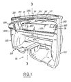
- a dividing wall perfected according to the invention is intended to equip a structure 10 of a motor vehicle to separate a front compartment, for example engine M from a living space H.
- this structure 10 only partially shown and schematically comprises an awning 11, a lower crossmember 12, a front spar 13, lateral uprights 14 and carries connectors not shown, for example flexible connectors, a steering column and pedal support 16 with a set of pedal pedals 17 and a steering column 18. All of this is conventional and , for example, disclosed in the aforementioned patent applications.
- a separating partition according to the invention comprises a panel 20, practically rectangular, the four sides of which, the large 201 and the small 202, are provided with a peripheral flange 203. These sides delimit a central bowl 204 with a bottom 205.
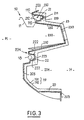
- this panel is shaped to obtain at least two beams, a marginal beam 21 and a median beam 22, both longitudinal and practically parallel to the long sides 201. It can be seen that these two beams 21 and 22 have a approximately U-shaped cross section and are open opposite this bottom 205. As can be seen, the two beams 21, 22 are practically continuous from one of the short sides 202 to the other. As can be seen, the marginal beam 21 is located near one of the long sides 201 while the middle beam 22 is located near the middle of the bowl 204.
- the marginal beam 21 comprises two wings 212 vis-à-vis practically parallel to the long sides 201, and a bridge 213 connecting the wings 212. From preferably, at least one hearing 211 locally pierces the beam 21, preferably the bridge 213. As can be observed, on either side of the marginal beam 21, outside the wings 212, the bottom 205 of the central bowl forms bases 110. These bases are more particularly intended to receive the canopy 11. In this way, it is understood that this beam, initially open, can then be closed and thus forms a box 210, very especially suitable for serving as a conduit. air for an air conditioning system not shown.
- the arrangement of the gills 211, their orientation and their distribution, possibly supplemented by illustrated side vents, makes it possible to distribute an air curtain towards the windshield or flows in the passenger compartment; this is well known and that is why we will not extend it further.
- the central beam 22 comprises two opposite wings 222, practically parallel to the long sides 201 and a bridge 223 connecting the wings 222. As can be observed, this central beam is pierced with a orifice 221 intended to be crossed by a shaft 181 of a steering column 18.
- the separating partition according to the invention comprises a panel 20 which is also shaped to obtain an intermediate beam 23 which is also practically parallel to the long sides 201.
- this intermediate beam 23 is located between the beams marginal 21 and median 22. It can also be noted that this beam is discontinuous, interrupted between the two short sides 202 by a depression 231.
- the intermediate beam 23 has an approximately U-shaped configuration and is open opposite the bottom 205. As we can observe it, the height above the bottom 205 of this intermediate beam 23 is greater than that of the marginal 21 and median beams 22.
- this intermediate beam is shaped to form an enclosure 230 intended to receive accessories.
- this intermediate beam 23 in the configuration of a flared U is delimited by two opposite sides 232 and by a facade 233 joining them. It can be noted that the depression 231 is delimited by cheeks 2310 opposite practically perpendicular to these flank 232 and facade 233. It will also be observed that this intermediate beam 23 is crossed by openings 2311 and clearances 2312 situated, preferably, on the facade 233.
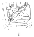
- the bottom 205 is pierced with cutouts 206 for crossing the connectors and passages 207 for the pedals of a crankset 17.
- the pedals of the crankset 17 are carried by a support steering column-pedal 16 which is housed in depression 231.
- This bottom also forms supports 280 for receiving a brake assist system and a rack mounting of the steering column.
- the bottom 205 comprises, between the central beam 22 and the long side 201 opposite to that close to the marginal beam 21, supports 121 and seats 122 for receiving, respectively, the lower cross member 12 and spar before 13 of the framework 10 which was discussed previously.
- peripheral rim 203 carries, on its short sides 202, supports 114 intended to receive the lateral uprights 14 of the structure.
- the partition according to the invention serves as a service, a servant workshop for assembly since it can receive, on one side, a steering rack support and a brake assist system and, on the other side, a dashboard and a column support steering-crankset.
- Such a separating partition according to the invention can be manufactured with synthetic materials to which fillers and / or reinforcements are added in the form of suitable fibers, in order to give it the desired properties, in particular mechanical.
- synthetic materials to which fillers and / or reinforcements are added in the form of suitable fibers, in order to give it the desired properties, in particular mechanical.
- SMC Sheet Molding Compound
- TRE Reinforced Thermoplastic Estempable
- this partition according to the invention is provided with a coating 19 based on foam 191 carrying on its outer face a septum or film 192 to give it an attractive look and feel, like it is classic.
- this improved partition according to the invention also serves as a thermal barrier and also plays the role of fire barrier according to the standards applicable in the matter.
Landscapes
- Engineering & Computer Science (AREA)
- Chemical & Material Sciences (AREA)
- Combustion & Propulsion (AREA)
- Transportation (AREA)
- Mechanical Engineering (AREA)
- Body Structure For Vehicles (AREA)
- Vehicle Step Arrangements And Article Storage (AREA)
Applications Claiming Priority (2)
| Application Number | Priority Date | Filing Date | Title |
|---|---|---|---|
| FR9000628A FR2657319B1 (fr) | 1990-01-19 | 1990-01-19 | Cloison separatrice pour coque de vehicule automobile. |
| FR9000628 | 1990-01-19 |
Publications (2)
| Publication Number | Publication Date |
|---|---|
| EP0438325A1 true EP0438325A1 (de) | 1991-07-24 |
| EP0438325B1 EP0438325B1 (de) | 1992-07-15 |
Family
ID=9392952
Family Applications (1)
| Application Number | Title | Priority Date | Filing Date |
|---|---|---|---|
| EP19910400002 Expired - Lifetime EP0438325B1 (de) | 1990-01-19 | 1991-01-02 | Trennwand für die Karosserie eines Kraftfahrzeuges |
Country Status (4)
| Country | Link |
|---|---|
| EP (1) | EP0438325B1 (de) |
| DE (1) | DE69100002T2 (de) |
| ES (1) | ES2033561T3 (de) |
| FR (1) | FR2657319B1 (de) |
Cited By (2)
| Publication number | Priority date | Publication date | Assignee | Title |
|---|---|---|---|---|
| DE4440973A1 (de) * | 1994-11-17 | 1996-05-30 | Daimler Benz Ag | Trennwand zwischen einem Motorraum und einem Fahrgastraum eines Personenkraftwagens |
| GB2348175A (en) * | 1999-03-26 | 2000-09-27 | Rover Group | Vehicle body having bulkhead secured by adhesive or sealant |
Families Citing this family (6)
| Publication number | Priority date | Publication date | Assignee | Title |
|---|---|---|---|---|
| DE4430920C1 (de) * | 1994-08-31 | 1996-03-07 | Daimler Benz Ag | Aussteifung für eine Stirnwand eines Fahrgastraumes eines Kraftfahrzeuges |
| DE19749294C1 (de) * | 1997-11-07 | 1999-04-01 | Daimler Benz Ag | Karosseriestruktur mit wenigstens einer Querverbindung |
| DE19925840B4 (de) * | 1999-06-01 | 2004-07-08 | Brose Fahrzeugteile Gmbh & Co. Kg, Coburg | Karosserieteil für Kraftfahrzeuge sowie Verfahren zu dessen Herstellung |
| DE10260534B4 (de) * | 2002-12-21 | 2016-02-11 | Volkswagen Ag | Vorderwagen eines Kraftfahrzeugs |
| DE102005047651B4 (de) * | 2005-10-05 | 2019-06-19 | Volkswagen Ag | Stirnwandisolationsanordnung |
| DE102009006960A1 (de) * | 2009-01-31 | 2010-08-05 | Aksys Gmbh | Fahrzeug-Instrumententafel-Montageträger und Verfahren zur Herstellung eines Fahrzeug-Instrumententafel-Montageträgers |
Citations (2)
| Publication number | Priority date | Publication date | Assignee | Title |
|---|---|---|---|---|
| FR2614257A1 (fr) * | 1987-04-27 | 1988-10-28 | Peugeot Aciers Et Outillage | Piece de structure pour vehicule automobile et son application notamment au montage automatique de ce dernier. |
| EP0291385A1 (de) * | 1987-05-13 | 1988-11-17 | Ecia - Equipements Et Composants Pour L'industrie Automobile | Modulare Struktur für Fahrzeuge und ihre Verwendung in der automatischen Montage |
-
1990
- 1990-01-19 FR FR9000628A patent/FR2657319B1/fr not_active Expired - Lifetime
-
1991
- 1991-01-02 EP EP19910400002 patent/EP0438325B1/de not_active Expired - Lifetime
- 1991-01-02 ES ES91400002T patent/ES2033561T3/es not_active Expired - Lifetime
- 1991-01-02 DE DE1991600002 patent/DE69100002T2/de not_active Expired - Fee Related
Patent Citations (2)
| Publication number | Priority date | Publication date | Assignee | Title |
|---|---|---|---|---|
| FR2614257A1 (fr) * | 1987-04-27 | 1988-10-28 | Peugeot Aciers Et Outillage | Piece de structure pour vehicule automobile et son application notamment au montage automatique de ce dernier. |
| EP0291385A1 (de) * | 1987-05-13 | 1988-11-17 | Ecia - Equipements Et Composants Pour L'industrie Automobile | Modulare Struktur für Fahrzeuge und ihre Verwendung in der automatischen Montage |
Cited By (2)
| Publication number | Priority date | Publication date | Assignee | Title |
|---|---|---|---|---|
| DE4440973A1 (de) * | 1994-11-17 | 1996-05-30 | Daimler Benz Ag | Trennwand zwischen einem Motorraum und einem Fahrgastraum eines Personenkraftwagens |
| GB2348175A (en) * | 1999-03-26 | 2000-09-27 | Rover Group | Vehicle body having bulkhead secured by adhesive or sealant |
Also Published As
| Publication number | Publication date |
|---|---|
| FR2657319A1 (fr) | 1991-07-26 |
| DE69100002D1 (de) | 1992-08-20 |
| ES2033561T3 (es) | 1993-03-16 |
| DE69100002T2 (de) | 1993-03-04 |
| FR2657319B1 (fr) | 1992-05-15 |
| EP0438325B1 (de) | 1992-07-15 |
Similar Documents
| Publication | Publication Date | Title |
|---|---|---|
| EP0515287B1 (de) | Armaturenbrett eines Kraftfahrzeugs | |
| EP2852502B1 (de) | Windschutzfenster mit einer scheibe, die mit einer integrierten einlage ausgerüstet ist, die eine zu einem träger des fahrzeugrahmens passende form aufweist | |
| EP2448815B1 (de) | Rahmenkonstruktion für eine öffnung in einem flugzeugrumpf | |
| EP0994006B1 (de) | Verfahren zum Herstellen eines Tragwerks für die Frontseite von Kraftfahrzeugen ,und Tragwerk für die Frontseite von Kraftfahrzeugen hergestellt durch dieses Verfahren | |
| EP0291385B1 (de) | Modulare Struktur für Fahrzeuge und ihre Verwendung in der automatischen Montage | |
| EP1063151A9 (de) | Cockpit | |
| EP0438325B1 (de) | Trennwand für die Karosserie eines Kraftfahrzeuges | |
| EP0519776B1 (de) | Verbessertes Frontteil eines Kraftfahrzeuges | |
| FR2668436A1 (fr) | Facade de vehicule a pare-chocs au moins partiellement incorpore. | |
| EP1308374A1 (de) | Verfahren zur Herstellen von zwei Armaturenbrettern durch Benutzung von zwei Luftschläuchen | |
| DE19534661A1 (de) | Türinnenverkleidung zur Befestigung an einer Innenschale einer Kraftfahrzeugtür | |
| FR2692541A1 (fr) | Véhicule ferroviaire formé par assemblage modulaire. | |
| EP0431986B1 (de) | Verbessertes Strukturteil für ein Fahrzeug und seine Verwendung bei einer automatischen Montage | |
| EP3261904A1 (de) | Verbesserte verstärkungseinsatzanordnung mittels eines polymermaterials und technische kraftfahrzeugfrontfläche mit solch einer anordnung | |
| EP3283354B1 (de) | Technische vorderflächenstruktur eines kraftfahrzeugs aus kunststoff | |
| WO2016030589A1 (fr) | Assemblage d'inserts de renfort par un matériau polymère, notamment pour face avant technique de véhicule, cet assemblage étant renforce par sa fixation a un élément de structure | |
| EP0304366A1 (de) | Strukturteil für ein Fahrzeug, das an letzterem befestigt ist, um wenigstens teilweise als Trennwand zu dienen | |
| FR2659617A1 (fr) | Element de structure pour caisse ou coque de vehicule automobile. | |
| FR3071864A1 (fr) | Panneau vitre a pourtour polymerique, armatures de renfort et armatures de fixation | |
| FR2643034A1 (fr) | Procede de construction d'un vehicule automobile et vehicule obtenu par ce procede | |
| FR2698426A1 (fr) | Support élastique à rigidités bi ou tridirectionnelles fortement différentes. | |
| FR2831511A1 (fr) | Cabine de vehicule realisee par assemblage de troncon de profile | |
| EP3501954A1 (de) | Einteilige bodenstruktur aus verbundmaterial | |
| EP1852338A1 (de) | Campingwagen, dessen Fahrerkabine ein Profil umfasst | |
| WO2009053199A1 (fr) | Face avant pour véhicule automobile |
Legal Events
| Date | Code | Title | Description |
|---|---|---|---|
| PUAI | Public reference made under article 153(3) epc to a published international application that has entered the european phase |
Free format text: ORIGINAL CODE: 0009012 |
|
| AK | Designated contracting states |
Kind code of ref document: A1 Designated state(s): DE ES GB IT SE |
|
| 17P | Request for examination filed |
Effective date: 19910604 |
|
| 17Q | First examination report despatched |
Effective date: 19911217 |
|
| GRAA | (expected) grant |
Free format text: ORIGINAL CODE: 0009210 |
|
| ITF | It: translation for a ep patent filed | ||
| AK | Designated contracting states |
Kind code of ref document: B1 Designated state(s): DE ES GB IT SE |
|
| PG25 | Lapsed in a contracting state [announced via postgrant information from national office to epo] |
Ref country code: SE Effective date: 19920722 |
|
| REF | Corresponds to: |
Ref document number: 69100002 Country of ref document: DE Date of ref document: 19920820 |
|
| GBT | Gb: translation of ep patent filed (gb section 77(6)(a)/1977) | ||
| REG | Reference to a national code |
Ref country code: ES Ref legal event code: FG2A Ref document number: 2033561 Country of ref document: ES Kind code of ref document: T3 |
|
| PLBE | No opposition filed within time limit |
Free format text: ORIGINAL CODE: 0009261 |
|
| STAA | Information on the status of an ep patent application or granted ep patent |
Free format text: STATUS: NO OPPOSITION FILED WITHIN TIME LIMIT |
|
| 26N | No opposition filed | ||
| PGFP | Annual fee paid to national office [announced via postgrant information from national office to epo] |
Ref country code: GB Payment date: 19981229 Year of fee payment: 9 |
|
| PGFP | Annual fee paid to national office [announced via postgrant information from national office to epo] |
Ref country code: DE Payment date: 19990107 Year of fee payment: 9 |
|
| PGFP | Annual fee paid to national office [announced via postgrant information from national office to epo] |
Ref country code: ES Payment date: 19990118 Year of fee payment: 9 |
|
| PG25 | Lapsed in a contracting state [announced via postgrant information from national office to epo] |
Ref country code: GB Free format text: LAPSE BECAUSE OF NON-PAYMENT OF DUE FEES Effective date: 20000102 |
|
| PG25 | Lapsed in a contracting state [announced via postgrant information from national office to epo] |
Ref country code: ES Free format text: LAPSE BECAUSE OF NON-PAYMENT OF DUE FEES Effective date: 20000103 |
|
| GBPC | Gb: european patent ceased through non-payment of renewal fee |
Effective date: 20000102 |
|
| PG25 | Lapsed in a contracting state [announced via postgrant information from national office to epo] |
Ref country code: DE Free format text: LAPSE BECAUSE OF NON-PAYMENT OF DUE FEES Effective date: 20001101 |
|
| REG | Reference to a national code |
Ref country code: ES Ref legal event code: FD2A Effective date: 20011010 |
|
| PG25 | Lapsed in a contracting state [announced via postgrant information from national office to epo] |
Ref country code: IT Free format text: LAPSE BECAUSE OF NON-PAYMENT OF DUE FEES;WARNING: LAPSES OF ITALIAN PATENTS WITH EFFECTIVE DATE BEFORE 2007 MAY HAVE OCCURRED AT ANY TIME BEFORE 2007. THE CORRECT EFFECTIVE DATE MAY BE DIFFERENT FROM THE ONE RECORDED. Effective date: 20050102 |