EP0437262B2 - Method for preventive consolidation of the soil for underground minings - Google Patents
Method for preventive consolidation of the soil for underground minings Download PDFInfo
- Publication number
- EP0437262B2 EP0437262B2 EP91100265A EP91100265A EP0437262B2 EP 0437262 B2 EP0437262 B2 EP 0437262B2 EP 91100265 A EP91100265 A EP 91100265A EP 91100265 A EP91100265 A EP 91100265A EP 0437262 B2 EP0437262 B2 EP 0437262B2
- Authority
- EP
- European Patent Office
- Prior art keywords
- tube
- soil
- rod
- hollow
- excavation
- Prior art date
- Legal status (The legal status is an assumption and is not a legal conclusion. Google has not performed a legal analysis and makes no representation as to the accuracy of the status listed.)
- Expired - Lifetime
Links
Images

Classifications
-
- E—FIXED CONSTRUCTIONS
- E02—HYDRAULIC ENGINEERING; FOUNDATIONS; SOIL SHIFTING
- E02D—FOUNDATIONS; EXCAVATIONS; EMBANKMENTS; UNDERGROUND OR UNDERWATER STRUCTURES
- E02D3/00—Improving or preserving soil or rock, e.g. preserving permafrost soil
- E02D3/12—Consolidating by placing solidifying or pore-filling substances in the soil
-
- E—FIXED CONSTRUCTIONS
- E21—EARTH DRILLING; MINING
- E21D—SHAFTS; TUNNELS; GALLERIES; LARGE UNDERGROUND CHAMBERS
- E21D20/00—Setting anchoring-bolts
- E21D20/02—Setting anchoring-bolts with provisions for grouting
Abstract
Description
According to the known technique of drilling first and then injecting from the bottom of the borehole, the metal reinforcement can be fitted only when the column is formed. Two alternative methods can be used:
- a reinforcing steel tube is inserted as soon as the column is completed, therefore the tube will tend to move, because if its weight, to the lower part of the semi-solid column and it will not be coaxial with respect to it;
- the reinforcing tube is inserted in the column when this is already stiff, after having drilled the centre of the column; then it should be sealed by injecting additional grout.
Claims (2)
- A method for stabilising the soil for tunnel excavations by inserting into the soil arrays of steel tubes for the injection of grout about an intended tunnel excavation,
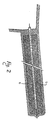
characterised in that it comprises the steps of:locating a said hollow tube (1) at an excavation site;positioning a hollow rod (2) with nozzles co-axially within said hollow tube (1) wherein an annular space (5) is defined between the rod (2) and the tube (1), the hollow rod being fitted with a boring tool (3) at one end thereof;rotating the hollow tube (1) and the hollow rod (2) for excavating material from said excavation site by means of said boring tool (3);simultaneously injecting a high pressurised liquid mixture through said hollow rod (2) into said excavation site through radially positioned nozzles proximate to the boring tool during rotation of the hollow tube (1) and the hollow rod (2) thereby increasing the diameter of the excavation, wherein a portion of the finest part of the excavated soil is removed from the excavation site via said annular space (5) and said liquid mixture admixes with the remaining portion of the excavated material for forming a stiffening column (6) of soil and liquid mixture around the tube (1) behind the boring tool as it progresses into the soil; andremoving said rod (2) from the hollow tube (1) subsequent to achieving the desired length of column (6). - A method according to Claim 1, characterised in that during excavation the tube (1) and the rod (2) are forced to proceed simultaneously and are rotated in opposite directions.
Applications Claiming Priority (2)
| Application Number | Priority Date | Filing Date | Title |
|---|---|---|---|
| IT330690 | 1990-01-11 | ||
| IT00330690A IT1238428B (en) | 1990-01-11 | 1990-01-11 | PROCEDURE FOR THE PREVENTIVE CONSOLIDATION OF GALLERY EXCAVATIONS USING THE PROTECTIVE UMBRELLA TECHNIQUE |
Publications (3)
| Publication Number | Publication Date |
|---|---|
| EP0437262A1 EP0437262A1 (en) | 1991-07-17 |
| EP0437262B1 EP0437262B1 (en) | 1994-07-27 |
| EP0437262B2 true EP0437262B2 (en) | 1998-01-14 |
Family
ID=11104658
Family Applications (1)
| Application Number | Title | Priority Date | Filing Date |
|---|---|---|---|
| EP91100265A Expired - Lifetime EP0437262B2 (en) | 1990-01-11 | 1991-01-10 | Method for preventive consolidation of the soil for underground minings |
Country Status (4)
| Country | Link |
|---|---|
| EP (1) | EP0437262B2 (en) |
| AT (1) | ATE109234T1 (en) |
| DE (1) | DE69103027T3 (en) |
| IT (1) | IT1238428B (en) |
Families Citing this family (3)
| Publication number | Priority date | Publication date | Assignee | Title |
|---|---|---|---|---|
| JPH089863B2 (en) * | 1991-08-14 | 1996-01-31 | 株式会社エヌ、アイ、テイ | All-angle ground improvement body construction method and its equipment |
| RU2468207C1 (en) * | 2011-04-05 | 2012-11-27 | Государственное образовательное учреждение высшего профессионального образования "Санкт-Петербургский государственный горный институт имени Г.В. Плеханова (технический университет)" | Method for reinforcement of mines soil |
| CN104564113B (en) * | 2015-01-15 | 2016-08-17 | 山东科技大学 | The construction method of roadway surrounding rock fiber slurry grouting and reinforcing |
Family Cites Families (2)
| Publication number | Priority date | Publication date | Assignee | Title |
|---|---|---|---|---|
| IT1208123B (en) * | 1983-04-19 | 1989-06-06 | Fondedile Spa | CONGLOMERATE COLUMN MADE IN THE GROUND IN SITU BY PLACING INERT MATERIALS DURING PERFORATION AND CONTEMPORARY OR SUBSEQUENT INJECTION WITH SUITABLE BINDERS, RELEVANT EXECUTION PROCEDURES |
| CH665878A5 (en) * | 1984-12-11 | 1988-06-15 | Rodio Found Eng Ltd | PROCEDURE FOR THE CONSOLIDATION OF LAND IN THE EXCAVATION OF GALLERIES. |
-
1990
- 1990-01-11 IT IT00330690A patent/IT1238428B/en active IP Right Grant
-
1991
- 1991-01-10 EP EP91100265A patent/EP0437262B2/en not_active Expired - Lifetime
- 1991-01-10 AT AT91100265T patent/ATE109234T1/en not_active IP Right Cessation
- 1991-01-10 DE DE69103027T patent/DE69103027T3/en not_active Expired - Lifetime
Also Published As
| Publication number | Publication date |
|---|---|
| DE69103027D1 (en) | 1994-09-01 |
| EP0437262B1 (en) | 1994-07-27 |
| DE69103027T2 (en) | 1994-11-17 |
| EP0437262A1 (en) | 1991-07-17 |
| IT1238428B (en) | 1993-07-26 |
| IT9003306A1 (en) | 1991-07-12 |
| ATE109234T1 (en) | 1994-08-15 |
| DE69103027T3 (en) | 1998-06-10 |
| IT9003306A0 (en) | 1990-01-11 |
Similar Documents
| Publication | Publication Date | Title |
|---|---|---|
| WO2000032906A1 (en) | Sardine-bone construction method for large-section tunnel | |
| KR20190023619A (en) | Tunnel Reinforcement structure and Tunnel Reinforcement methods using the same | |
| US6120214A (en) | Process for constructing reinforced subterranean columns | |
| US3839871A (en) | Earthen dam repair | |
| CA2456303C (en) | Continuous method of realization of underground tunnels including peripheral perforations | |
| EP0437262B2 (en) | Method for preventive consolidation of the soil for underground minings | |
| US9181673B2 (en) | Tools and methods for constructing large diameter underground piles | |
| KR101241382B1 (en) | Micro pile capable of withdrawing upper cassing and method for constructing foundation using the same | |
| US5152638A (en) | Process and apparatus for excavating tunnels | |
| KR101985267B1 (en) | Grouting device for inhibiting slime discharge and grouting method for jet using the same | |
| US5380127A (en) | Non-entry method of underground excavation in weak or water bearing grounds | |
| US20200032477A1 (en) | Cutting Tool Adapter and Method of Underpinning Structures Using Cutting Tool Adapter for Soil Mixing | |
| JP3450639B2 (en) | Rock bolt driving method and rock bolt driving machine | |
| JP3306460B2 (en) | Pile driving method | |
| WO1995015419A1 (en) | Ground boring device and method for constructing an underground wall using the same | |
| JPS5841373B2 (en) | Kankei Kou Zou Bzaiodo Souniuchi Komu Houtou Souchi | |
| JP3455157B2 (en) | Shoring construction method | |
| JP3735152B2 (en) | Tunnel excavation method | |
| JPH06100080B2 (en) | Large-section tunnel construction method and ground solidification column construction device | |
| JPH05321511A (en) | Construction method for underground vessel in weak ground | |
| WO2000044994A1 (en) | Soil mixing process | |
| Ressi di Cervia | New techniques in difficult ground tunneling | |
| JPH0882186A (en) | Construction method of horizontal mortar tunnel | |
| JPH0427012A (en) | Construction of earth anchor | |
| JPH07158389A (en) | Working face independence method in collapse bedrock tunnel |
Legal Events
| Date | Code | Title | Description |
|---|---|---|---|
| PUAI | Public reference made under article 153(3) epc to a published international application that has entered the european phase |
Free format text: ORIGINAL CODE: 0009012 |
|
| AK | Designated contracting states |
Kind code of ref document: A1 Designated state(s): AT DE ES FR GB GR IT NL |
|
| 17P | Request for examination filed |
Effective date: 19911023 |
|
| 17Q | First examination report despatched |
Effective date: 19921015 |
|
| GRAA | (expected) grant |
Free format text: ORIGINAL CODE: 0009210 |
|
| AK | Designated contracting states |
Kind code of ref document: B1 Designated state(s): AT DE ES FR GB GR IT NL |
|
| PG25 | Lapsed in a contracting state [announced via postgrant information from national office to epo] |
Ref country code: ES Free format text: THE PATENT HAS BEEN ANNULLED BY A DECISION OF A NATIONAL AUTHORITY Effective date: 19940727 Ref country code: AT Effective date: 19940727 Ref country code: GR Free format text: LAPSE BECAUSE OF FAILURE TO SUBMIT A TRANSLATION OF THE DESCRIPTION OR TO PAY THE FEE WITHIN THE PRESCRIBED TIME-LIMIT Effective date: 19940727 Ref country code: NL Effective date: 19940727 |
|
| REF | Corresponds to: |
Ref document number: 109234 Country of ref document: AT Date of ref document: 19940815 Kind code of ref document: T |
|
| REF | Corresponds to: |
Ref document number: 69103027 Country of ref document: DE Date of ref document: 19940901 |
|
| ITF | It: translation for a ep patent filed |
Owner name: BARZANO'E ZANARDO S.P.A. |
|
| ET | Fr: translation filed | ||
| PG25 | Lapsed in a contracting state [announced via postgrant information from national office to epo] |
Ref country code: GB Effective date: 19950110 |
|
| NLV1 | Nl: lapsed or annulled due to failure to fulfill the requirements of art. 29p and 29m of the patents act | ||
| PLBI | Opposition filed |
Free format text: ORIGINAL CODE: 0009260 |
|
| 26 | Opposition filed |
Opponent name: BAUER SPEZIALTIEFBAU GMBH Effective date: 19950420 |
|
| GBPC | Gb: european patent ceased through non-payment of renewal fee |
Effective date: 19950110 |
|
| PLAW | Interlocutory decision in opposition |
Free format text: ORIGINAL CODE: EPIDOS IDOP |
|
| PLAW | Interlocutory decision in opposition |
Free format text: ORIGINAL CODE: EPIDOS IDOP |
|
| PUAH | Patent maintained in amended form |
Free format text: ORIGINAL CODE: 0009272 |
|
| STAA | Information on the status of an ep patent application or granted ep patent |
Free format text: STATUS: PATENT MAINTAINED AS AMENDED |
|
| 27A | Patent maintained in amended form |
Effective date: 19980114 |
|
| AK | Designated contracting states |
Kind code of ref document: B2 Designated state(s): AT DE ES FR GB GR IT NL |
|
| ITF | It: translation for a ep patent filed |
Owner name: BARZANO'E ZANARDO S.P.A. |
|
| ET3 | Fr: translation filed ** decision concerning opposition | ||
| PG25 | Lapsed in a contracting state [announced via postgrant information from national office to epo] |
Ref country code: IT Free format text: LAPSE BECAUSE OF NON-PAYMENT OF DUE FEES;WARNING: LAPSES OF ITALIAN PATENTS WITH EFFECTIVE DATE BEFORE 2007 MAY HAVE OCCURRED AT ANY TIME BEFORE 2007. THE CORRECT EFFECTIVE DATE MAY BE DIFFERENT FROM THE ONE RECORDED. Effective date: 20050110 |
|
| PLAB | Opposition data, opponent's data or that of the opponent's representative modified |
Free format text: ORIGINAL CODE: 0009299OPPO |
|
| PGRI | Patent reinstated in contracting state [announced from national office to epo] |
Ref country code: IT Effective date: 20091201 |
|
| PGFP | Annual fee paid to national office [announced via postgrant information from national office to epo] |
Ref country code: FR Payment date: 20100208 Year of fee payment: 20 |
|
| PGFP | Annual fee paid to national office [announced via postgrant information from national office to epo] |
Ref country code: DE Payment date: 20100107 Year of fee payment: 20 |
|
| PGRI | Patent reinstated in contracting state [announced from national office to epo] |
Ref country code: IT Effective date: 20091201 |
|
| PGFP | Annual fee paid to national office [announced via postgrant information from national office to epo] |
Ref country code: IT Payment date: 20100125 Year of fee payment: 20 |
|
| PGRI | Patent reinstated in contracting state [announced from national office to epo] |
Ref country code: IT Effective date: 20110616 |
|
| PG25 | Lapsed in a contracting state [announced via postgrant information from national office to epo] |
Ref country code: DE Free format text: LAPSE BECAUSE OF EXPIRATION OF PROTECTION Effective date: 20110110 |