EP0435569B2 - Radial schrumpfbare Muffe zum Einschliessen einer Verbindung oder eines Anschlusses eines elektrischen Kabels - Google Patents
Radial schrumpfbare Muffe zum Einschliessen einer Verbindung oder eines Anschlusses eines elektrischen Kabels Download PDFInfo
- Publication number
- EP0435569B2 EP0435569B2 EP90313978A EP90313978A EP0435569B2 EP 0435569 B2 EP0435569 B2 EP 0435569B2 EP 90313978 A EP90313978 A EP 90313978A EP 90313978 A EP90313978 A EP 90313978A EP 0435569 B2 EP0435569 B2 EP 0435569B2
- Authority
- EP
- European Patent Office
- Prior art keywords
- sleeve
- layer
- conductive
- semi
- cable
- Prior art date
- Legal status (The legal status is an assumption and is not a legal conclusion. Google has not performed a legal analysis and makes no representation as to the accuracy of the status listed.)
- Expired - Lifetime
Links
- 239000004020 conductor Substances 0.000 claims description 29
- 238000009413 insulation Methods 0.000 claims description 22
- 239000000463 material Substances 0.000 claims description 22
- 230000000452 restraining effect Effects 0.000 claims description 14
- 239000003989 dielectric material Substances 0.000 claims description 10
- 238000001746 injection moulding Methods 0.000 claims description 10
- 229920002379 silicone rubber Polymers 0.000 claims description 6
- 230000000717 retained effect Effects 0.000 claims description 4
- 239000004944 Liquid Silicone Rubber Substances 0.000 claims description 3
- 239000006229 carbon black Substances 0.000 claims description 2
- 229920001296 polysiloxane Polymers 0.000 claims 7
- 239000004945 silicone rubber Substances 0.000 claims 1
- 230000001276 controlling effect Effects 0.000 description 10
- 238000000034 method Methods 0.000 description 7
- 230000015556 catabolic process Effects 0.000 description 5
- 230000000694 effects Effects 0.000 description 5
- 239000013536 elastomeric material Substances 0.000 description 4
- 238000001125 extrusion Methods 0.000 description 4
- 238000009826 distribution Methods 0.000 description 3
- 230000005684 electric field Effects 0.000 description 3
- 239000002654 heat shrinkable material Substances 0.000 description 3
- 238000004519 manufacturing process Methods 0.000 description 3
- 230000035515 penetration Effects 0.000 description 3
- 238000007789 sealing Methods 0.000 description 3
- 230000007704 transition Effects 0.000 description 3
- XLYOFNOQVPJJNP-UHFFFAOYSA-N water Substances O XLYOFNOQVPJJNP-UHFFFAOYSA-N 0.000 description 3
- 150000001875 compounds Chemical class 0.000 description 2
- HIHIPCDUFKZOSL-UHFFFAOYSA-N ethenyl(methyl)silicon Chemical compound C[Si]C=C HIHIPCDUFKZOSL-UHFFFAOYSA-N 0.000 description 2
- 239000012774 insulation material Substances 0.000 description 2
- 238000003754 machining Methods 0.000 description 2
- 239000004065 semiconductor Substances 0.000 description 2
- RYGMFSIKBFXOCR-UHFFFAOYSA-N Copper Chemical compound [Cu] RYGMFSIKBFXOCR-UHFFFAOYSA-N 0.000 description 1
- 238000006073 displacement reaction Methods 0.000 description 1
- 239000013013 elastic material Substances 0.000 description 1
- 230000002349 favourable effect Effects 0.000 description 1
- 238000009434 installation Methods 0.000 description 1
- 239000011810 insulating material Substances 0.000 description 1
- 239000000203 mixture Substances 0.000 description 1
- 238000000465 moulding Methods 0.000 description 1
- 239000003973 paint Substances 0.000 description 1
- 239000002245 particle Substances 0.000 description 1
- 230000008092 positive effect Effects 0.000 description 1
- 238000009827 uniform distribution Methods 0.000 description 1
Images

Classifications
-
- H—ELECTRICITY
- H02—GENERATION; CONVERSION OR DISTRIBUTION OF ELECTRIC POWER
- H02G—INSTALLATION OF ELECTRIC CABLES OR LINES, OR OF COMBINED OPTICAL AND ELECTRIC CABLES OR LINES
- H02G15/00—Cable fittings
- H02G15/08—Cable junctions
- H02G15/18—Cable junctions protected by sleeves, e.g. for communication cable
- H02G15/184—Cable junctions protected by sleeves, e.g. for communication cable with devices for relieving electrical stress
-
- H—ELECTRICITY
- H02—GENERATION; CONVERSION OR DISTRIBUTION OF ELECTRIC POWER
- H02G—INSTALLATION OF ELECTRIC CABLES OR LINES, OR OF COMBINED OPTICAL AND ELECTRIC CABLES OR LINES
- H02G15/00—Cable fittings
- H02G15/08—Cable junctions
- H02G15/18—Cable junctions protected by sleeves, e.g. for communication cable
- H02G15/182—Cable junctions protected by sleeves, e.g. for communication cable held in expanded condition in radial direction prior to installation
- H02G15/1826—Cable junctions protected by sleeves, e.g. for communication cable held in expanded condition in radial direction prior to installation on a removable hollow core, e.g. a tube
- H02G15/1833—Cable junctions protected by sleeves, e.g. for communication cable held in expanded condition in radial direction prior to installation on a removable hollow core, e.g. a tube formed of helically wound strip with adjacent windings, which are removable by applying a pulling force to a strip end
Definitions
- the invention refers to a radially shrinkable sleeve for enclosing a connection or a terminal, respectively, of an electrical cable, particularly of a medium voltage cable.
- Radially shrinkable sleeves for enclosing a connection or termination of an electrical cable are known in various designs.
- the EPO application 0 272 131 discloses a sleeve arrangement wherein first a heat shrinkable sleeve of dielectric material is shrunk onto the connection area with the ends engaging the exposed field restraining layer of the cable ends. A conductive paint is coated onto the outer side of the shrinkable hose in the area of the connector element interconnecting the conductors.
- a double layer heat shrinkable sleeve of insulating material is shrunk onto the first sleeve, the length of the inner layer being somewhat larger than that of the outer layer so that a conical gradation is achieved for a geometrical capacitive field control.
- the placement of the sleeve arrangement in two steps is relatively time consuming. Further, it may occur that air is entrapped between the insulation layer and the field restraining layer which affects the electrical behavior.
- the cylindrical sleeve of this kind includes a field-controlling inner layer, a middle insulating layer and an electrically conducting outer layer.
- the electrically conducting layer consists of a heat shrinkable material so that the sleeve may be shrunachi the connection area after the connection has been made.
- the area between the field restraining layers of cables to be interconnected does not have a uniform cylindrical configuration, in particular, different radii occur in the range of the connector element.
- the individual sleeves or layers consist of elastomeric material and are individually retained in a radially expanded state by means of a supporting coil. If the coil is removed, the sleeve shrinks radially and engages the connection area or the layer therebelow.
- a compound sleeve which is made by extrusion and comprises an inner conductive or semi-conductive layer, a middle insulating layer and an outer conductive layer which also has heat shrinking properties.
- the extruded cylindrical sleeve is machined by a chip-forming process such that the inner diameter is conically enlarged toward the free ends in order to achieve geometrical capacitive field control.
- the machining of the known sleeve after forming the sleeve by extrusion is relatively expensive.
- the known sleeve also requires a preparing treatment in the connection area before it is radially shrunk.
- Cold shrinking sleeves held by a coil in a pre-stretched condition and heat shrinking sleeves have the advantage that they attain an inner diameter in the pre-stretched state which is larger than the outer diameter of the cable sheath. Therefore, such sleeves can be parked in a relatively favorable position on a cable end prior to establishing the conductor connection.
- integrally formed sleeves which are made by injection molding of relatively stiff elastomeric material. The known sleeve has a relatively small inner diameter at its ends. In order to attain a parking position on one end portion of a cable, it is necessary to remove the insulation throughout a greater length.
- the sleeve is pushed onto the connection area after the conductor connection has been established with the portions having a smaller diameter engaging the field restraining layer of the cable ends under pressure.
- the area of engagement must be relatively small and the pressure by which the field restraining layer is engaged must not be high, otherwise the displacement of the sleeve onto the connection area cannot be carried out by manual operation.
- the use of such sleeves has the advantage that the wrapping of dielectric tapes on the connection area prior to the placing of the sleeve can be omitted.
- a conductive electrode is positioned inside the sleeve which extends beyond both ends of the connector element and clampingly engages the insulation layer. Such electrode effects a uniform distribution of the field so that hollow spaces within the sleeve are not critical.
- an integral sleeve which includes a heat shrinkable insulation layer, the outer side thereof is provided with a semi-conductive layer while the inner side thereof is laminated with a conductive layer which contiguously engages the electrical connection after shrinking of the sleeve.
- the extremities of the sleeve are conically shaped.
- US patent 4,390,745 discloses a cylindrical sleeve composed of two separate sleeve portions of heat shrinkable material.
- the first or inner sleeve portion has an insulating layer, a dielectric portion at least at one extremity of the sleeve, and a conductive portion spaced from the dielectric portion being provided at the inner side of the insulating layer.
- the second or outer sleeve portion includes an insulating layer, a semi-conductive layer being provided at the outer side thereof.
- DE-A-3,001,158 discloses a sleeve for a high voltage cable comprising an inner layer of semiconductive material located between the ends of the sleeve, a radially outer layer of semiconductive material and a middle layer between the inner and outer layers.
- the semiconducting inner layer connects the semiconducting screens of the cable.
- the present invention provides a sleeve for enclosing a connection or a termination of an electrical cable, which can be simply manufactured and installed without great expense of time, which further provides a compact cable connection or a compact termination and which finally secures a sufficient tightness so that it can operate over a long time with high reliability.
- a radially shrinkable cylindrical sleeve in accordance with claim 1.
- the sleeve disclosed is a single piece part and substantially uniform cylindrically.
- the middle and the outer layer are conventionally structured and are of material which has a sufficient elasticity to be radially expanded and relaxed to be placed onto a cable connection or a cable termination.
- the inner layer includes at least one first end portion at one end of the sleeve consisting of permanent flexible dielectric material. It engages the field or stress restraining layer of the cable and has stress controlling properties to influence the field distribution at the end of the field restraining cable enclosure.
- a further portion of the inner layer of electrically conducting or semi-conducting material is located at a distance from the first portion which acts as an electrode and in case of a cable connection surrounds a connector element and engages the conductor insulation at both ends of the connector element.
- the portions of the inner layer are embedded in the material of the insulation layer, that the inner diameter of the end portion or portions and/or the second portion is substantially the same as of the middle or insulation layer.
- the sleeve accordinq to the invention cannot be molded by extrusion, rather, according to an embodiment of the invention, can be formed by injection molding by forming the layers successively.
- a method for injection molding of such sleeves has become known from the German patent specification 36 33 884.
- a series of cores having a shape corresponding to the cavity of the article is cyclically advanced through a series of mold cavities, and is provided, by injection molding, with a free core being present at the beginning of the series.
- each of the subsequent mold cavities a partial article is formed which is a subsequent layer of the article, and a finished article is removable at the end of the series, and is separated from the core.
- the sleeve according to the invention can be made by mass production without requiring a subsequent machining or the like.
- the integral sleeve according to the invention is radially shrinkable; for this two different techniques can be offered which both are known in the art.
- an outer layer is comprised of heat shrinkable material which in a radially stretched state retains the middle and the inner layer radially expanded.
- the individual layers of the sleeve according to the invention are formed by injection molding, they have to be bonded together. Therefore, the radially expanded outer layer may hold the middle and the inner layer in a stretched condition after a corresponding treatment. If for example the sleeve is shrunk onto a cable connection, the outer layer contracts radially, while the middle and the insulation layer follow this movement if they are made of elastomeric material.
- Compound sleeves which are structured in this manner and are adapted to be heat shrunk to elongated articles are for example known from US patent 4,207,364.
- the sleeve according to the invention can be retained in the radially stretched state by an internal support device, preferably a support core which is removed if a shrinking of the sleeve has to take place.
- This process is known as cold shrinking.
- Coils which are designed to retain a sleeve of elastomeric material in a radially stretched state are for example known from US patent 3,515,798 or the German patent specification 37 15 915. If such coils are used for cable sleeves which are composed of a multi layer, each layer is radially supported by a separate supporting coil.
- the material of the individual layers has to be sufficiently elastic or soft-elastic so that they may withstand the occurring forces.
- the middle insulating layer consists of liquid-silicon-rubber which has significant soft-resilient properties. It also turned out that due to the uniform cylindrical shape and the design of the inner layer, the overall wall thickness of the sleeve can be relatively small which meets the use of a mechanical support means.
- the one-piece structure of the sleeve according to the invention necessitates only one insulation layer in contrast to the known sleeve of US patent 4,390,745. Therefore, the insulation layer can be provided with a small thickness since the risk of air entrainments or the like can be excluded.
- the sleeve according to the invention has numerous positive effects. As already mentioned, it can be simply made by mass production. It can be extremely easily installed. The application of field or stress controlling tapes to the area of the connector element is unnecessary since the conducting or semi-conducting material of the second portion of the inner layer effects an equalizing of the field distribution. The dimensions of the sleeve according to the invention in its shrunk state enable a compact cable connection.
- the sleeve according to the invention is also extremely reliable and should retain its effectiveness over a sufficiently long period of time to afford nearly continuous service.
- the geometry of the sleeve according to the invention enables an effective stress control of the electrical field so that the danger of breakdowns and electrical discharges is very small.
- the sleeve according to the invention engages the cable and the connection area, respectively, over its total length whereby a sufficient sealing is achieved avoiding a penetration of water and humidity.
- the cable connection can be operated immediately after installation of the splice.
- the assembly of the sleeve according to the invention is possible preferably in the temperature range from ⁇ 0°C to + 40° C.
- the sleeve according to the invention can be stored for at least 6 months at a maximum temperature of + 40°C.
- the possible lifetime of the sleeve according to the invention is at least 20 years in which time period a sufficient sealing against the penetration of water and humidity is achieved.
- the necessary electrical properties according to the standard provisions can be met in the normally prevailing temperature range of + 5°C up to 90°C.
- the sleeve 10 shown in Figs. 1 and 2 is annularly cylindrical and includes an outer layer 11, a middle layer 12 and an inner layer which is composed of two end portions 14, 16 and a median portion 18 which is spaced from the end portions.
- the outer layer 11 has a uniform wall thickness and consists of semi-conductive material, e.g. semi-ccnductive Vinyl-Methyl-Silicon.
- the middle layer consists of an insulative cured liquid-silicone rubber.
- the end portions 14, 16 consist cf stress controlling dielectric material, e.g. Vinyl-Methyl-Silicon vulcanized at high temperature.
- the dissipation factor is below 0.1.
- the dielectric constant is between 15 and 25, preferably about 15.
- the stress controlling portions consist preferably of a material which is known from the German patent specification 30 08 264. It is a permanent-flexible dielectric material having an electrical volume resistivity at room temperature of at least 10 6 Ohm.cm.
- the base material is silicon rubber with a content of a finely divided conductive material to increase the relative dielectric constant.
- the conductive material comprises strongly structurized dustfine particles of a weakly conductive, electrically polarizable material in a mass content of up to about 350g per kg base material.
- the conductive material is carbon black.
- the median portion 18 acts as an electrode and consists of semi-conductive Vinyl-Methyl-Silicon-Mixture vulcanized at high temperature.
- the portions 14, 16 and 18 are embedded in the insulation material; but the outer and the inner surface of the sleeve 10 have a constant diameter.
- the sleeve is formed by injection molding wherein preferably first the portions 14, 16 and 18 are formed and thereafter the layers 12 and 11.
- a method is applied which is described in the German patent specification 36 33 884.
- the layerwise injection molding takes place by means of a plurality of cores having a shape corresponding to the cavity of the article, the cores being cyclically advanced through a series of mold cavities and is provided, by injection molding, with a free core being present at the beginning of the series.
- a partial article is formed which is a subsequent layer of the article, and a finished article is removable at the end of the series, and is separated from the core.
- All layers of sleeve 10 shown are of elastic material so that it can be radially stretched to a sufficient amount.
- the portions 14, 16 and 18 have preferably the same wall thickness.
- the inner diameter is for example 17.7 mm.
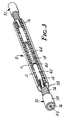
- the sleeve 10 is radially stretched for example to an inner diameter of 55 mm by a suitable device (not shown).
- a support coil 20 is introduced (Fig. 2) for example known from the German patent specification 37 15 915. Adjacent convolutions of the support coil 20 are interconnected in circumferential areas so that the coil may withstand the inherent radial forces of sleeve 10.
- the lefthand portion of the coil 10 is led back through the coil and can be manually gripped at 24. By withdrawing the coil 20 from the sleeve, the sleeve 10 may radially shrink.
- FIG. 3 the sleeve 10 is shrunk onto a cable connection.
- two ends 30, 32 of one-core cables are illustrated having a typical structure. This structure is to be briefly explained with the aid of cable end 30.
- a cable sheath 34 of suitable insulation material surrounds an earth conductor or shield 36 of copper wire which in turn surrounds an electrically semi-conductive screen 38. It serves as known for the restraint of the electrical field of conductor 40 which is surrounded by an insulation 42.
- the exposed conductors of the cable ends 30, 32 are interconnected by means of a connector element 44.
- the connector element 44 is crimped onto the conductors 40. To this purpose it is necessary to remove the insulation 42.
- the field restraining screen 38 is removed at a larger distance from the conductor end.
- the earth conductor 36 and the cable sheath 34 are removed at a still larger distance from the end as can be seen.
- the sleeve 10 is shrunk such that the portion 18 extends along the connector element 44 and engages the insulation 42.
- the portions 14, 16 of dielectric material are in engagement with the field restraining semi-conductive screen 38. It can be seen that the sleeve 10 when shrunk has a constant outer diameter and also approximately a constant inner diameter with some small deformations occurring at the transitions between the field restraining layer and the insulation 42 and between the insulation 42 and the conductor 40 or the connector element 44, respectively.
- the necessary field or stress controlling or field distributing effect of sleeve 10 thus does not take place through a geometric capacitive configuration, rather, exclusively by the stress controlling cylindrical portions 14, 16.
- the electrode 18 effects a uniform field distribution by defining a Faraday cage.
- a wrapping with a dielectric tape or the like prior to the shrinking of sleeve 10 is not necessary.
- the interstices between the insulation 42 and the connector element 44 or between the connector element 44 and the electrode 18 are of no importance and do not cause electrical discharges or breakdowns.
- sleeve 10 Before the shrinking step takes place and before making the electrical connection by means of the connector element 44, sleeve 10 is parked in a position on one cable end 30 or 32, respectively. After this, sleeve 10 is displaced and positioned in the connection area in its still radially stretched state. Subsequently, the support coil 20 is removed as described in connection with Fig. 2 so that sleeve 10 may be shrunk onto the cable connection. It is understood that after the shrinking of sleeve 10, respective end-sleeves (not shown) can be shrunk onto the transition area of cable sheath 34 and sleeve 10 which end sleeves may also consist of field or stress controlling dielectric material. Such conical sleeves are generally known.
- outer layer 11 is electrically connected to the shield 36 e.g. by means of a metallic net sleeve.
Landscapes
- Cable Accessories (AREA)
Claims (15)
- Radial schrumpfbare zylindrische Muffe zum Einschließen einer Verbindung bzw. eines Anschlusses eines elektrischen Kabels mit einem Leiter (40), einer den Leiter umgebenden Isolierung (42) und einer die Isolierung (42) umgebenden Feldabschirmschicht (38), wobei die Muffe eine erste innere Schicht, die mit der Feldabschirmschicht (38) in Eingriff treten kann, eine mittlere Schicht aus einem elektrisch isolierenden Material und eine äußere Schicht aus einem elektrisch halbleitenden Material besteht, so daß eine einstückige Muffe (10) entsteht, wobei die Muffe elastisch und permanent flexibel ist und elastisch gestreckt und im radial aufgeweiteten Zustand auf eine herausnehmbare Halterung (20) aufgebracht ist, dadurch gekennzeichnet, daß die innere Schicht (18) einen zylindrischen Abschnitt aus einem leitenden oder halbleitenden Material umfaßt, der zwischen den Enden der Muffe angeordnet ist und mit dem Leiter (40) oder einem muffenartigen Verbindungselement (44) und der angrenzenden Isolierung (42) in Eingriff treten kann, und mindestens ein zylindrischer Endabschnitt (14, 16) aus dielektrischem Material besteht und mit der Feldabschirmschicht (38) in Eingriff ist, um eine Feldsteuerung zu bewirken, daß die Halterung eine Spule (20) ist, und daß die Schichten zylindrische Abschnitte (14, 16, 12, 11) sind und aus Silicon bestehen, so daß die Muffe wieder in ihre entspannte Position zurückkehrt.
- Muffe nach Anspruch 1, dadurch gekennzeichnet, daß die Muffe entgegengesetzte Enden besitzt und die innere Schicht einen zylindrischen Abschnitt (18) aus einem leitenden oder halbleitenden Material umfaßt, der zwischen den Enden der Muffe (10) angeordnet ist, und daß der Innendurchmesser der Muffe zwischen den Enden einheitlich ist und die Innenseite ausschließlich durch den Endabschnitt und den muffenartigen Abschnitt (18) der inneren Schicht und der mittleren Schicht (12) begrenzt ist.
- Muffe nach Anspruch 1 oder 2, dadurch gekennzeichnet, daß die äußere Schicht aus halbleitendem Silicongummi besteht.
- Muffe nach Anspruch 1 oder 2, dadurch gekennzeichnet, daß die mittlere und/oder die äußere Schicht aus flüssigem Silicongummi hergestellt ist bzw. sind.
- Muffe nach Anspruch 2, dadurch gekennzeichnet, daß der Verlustfaktor des Endabschnitts unter 10% liegt.
- Muffe nach Anspruch 1, dadurch gekennzeichnet, daß die innere Schicht ein Paar zylindrischer Endabschnitte (14, 16) aus einem dielektrischen Vinyl-Methyl-Silicon und einen zylindrischen mittleren Abschnitt (18) aus halbleitendem Vinyl-Methyl-Silicon umlaßt, der zwischen den Endabschnitten und im Abstand von diesen angeordnet ist, und daß der mittlere Abschnitt (18) mit dem Leiter (40) oder einem muffenartigen Verbindungselement (44) und der angrenzenden Kabelisolierung (42) in Eingriff treten kann, daß die mittlere Schicht (12) aus einem elektrisch isolierenden Silicon besteht, das mit der inneren Schicht verklebt ist, und daß die äußere Schicht (11) ein elektrisch halbleilendes Vinyl-Methyl-Silicon umfaßt, das mit der mittleren Schicht verklebt ist, um eine einstückige Muffe (10) zu bilden, wobei die Schichten aus einem elastischen und permanent flexiblen Material bestehen, das in einem radial aufgeweiteten Zustand auf einer spulenartigen Halterung (20) gehalten werden kann, um die Schichten im aufgeweiteten Zustand zu halten, wobei die Spuleneinrichtung in der inneren Schicht angeordnet ist und die Halterung eine Spule (20) umfaßt, die so ausgebildet ist, daß sie entfernt werden kann, indem die Spule Lage für Lage abgewickelt wird, um die Spule aus der Muffe herauszuziehen, so daß die Muffe sich auf der Verbindung entspannen kann, und daß das halbleitende Material ein elektrisch polarisierbares Material umfaßt, um den gewünschten Leitwert herzustellen.
- Muffe nach Anspruch 6, dadurch gekennzeichnet, daß die Endabschnitte (14, 16) und der mittlere Abschnitt (18) in das Material der mittleren Schicht (12) eingebettet sind.
- Muffe nach Anspruch 7, dadurch gekennzeichnet, daß der Innendurchmesser des Endabschnitts (14) gleich dem der mittleren Schicht (18) ist.
- Muffe nach Anspruch 6, dadurch gekennzeichnet, daß die Schichten (14, 16, 18, 12, 11) nacheinander durch Spritzgießen hergestellt werden
- Muffe nach Anspruch 6, dadurch gekennzeichnet, daß der leitende oder halbleitende zylindrische Abschnitt (18) bei hoher Temperatur vulkanisiertes Vinyl-Methyl-Silicon ist.
- Langgestreckte zylindrische Muffe (10) zur Verbindung oder zum Abschluß eines isolierten Kabels mit einem Schirmgitter (38), umfassend eine äußere Umfangsschicht (11) aus halbleitendem Material, eine innere Umfangsschicht (14, 16, 18) mit einem ersten Abschnitt (14, 16) aus einem die Belastung kontrollierenden dielektrischen Material im Bereich von wenigstens einem Ende der Muffe in Längsrichtung, um mit dem Schirmgitter (38) des Kabels in Eingriff zu treten, und mit einem zweiten Abschnitt (18) aus halbleitendem oder leitendem Material, der von dem Ende entfernt ist, um mit dem Leiter (40) des Kabels oder einem muffenartigen Verbindungselement (44) und der angrenzenden Isolierung (42) in Eingriff zu treten, wobei die Muffe des weiteren eine Schicht aus einem elektrisch isolierenden Material (12) zwischen der inneren und der äußeren Schicht umfaßt, wobei die Schichten der Muffe miteinander verklebt sind, indem sie nacheinander durch Spritzgießen hergestellt wurden, so daß die Muffe einstückig ausgebildet ist, und wobei jede Schicht aus einem weichen elastischen und permanent flexiblen Material besteht, so daß die Muffe elastisch und radial von einem entspannten in einen gestreckten Zustand gestreckt werden kann, um auf eine herausnehmbare Halterung (20) aufgepaßt zu werden, und anschließend wieder in den entspannten Zustand zurückkehrt.
- Muffe nach Anspruch 11, bei der die Schicht aus elektrisch isolierendem Material zwischen der inneren und der äußeren Schicht und/oder die äußere Schicht(11) aus flüssigem Silicongummi hergestellt ist bzw. sind.
- Muffe nach Anspruch 11 oder 12, bei der der erste Abschnitt (14, 16) aus die Belastung kontrollierendem dielektrischen Material und/oder der zweite Abschnitt (18) aus bei hoher Temperatur vulkanisiertem Vinyl-Methyl-Silicon besteht bzw. bestehen.
- Muffe nach einem der Ansprüche 1 bis 13, bei der der erste Abschnitt (14, 16) aus die Belastung kon-trollierendem dielektrischem Material ein Mittel zur Erhöhung der Dielektrizitätskonstante, und zwar insbesondere Ruß enthält.
- Muffe nach einem der Ansprüche 11 bis 14, bei der die Dielektrizitätskonstante des ersten Abschnitts zwischen 15 und 25 liegt und vorzugsweise etwa 15 beträgt.
Applications Claiming Priority (2)
| Application Number | Priority Date | Filing Date | Title |
|---|---|---|---|
| DE3943296A DE3943296C2 (de) | 1989-12-29 | 1989-12-29 | Muffe zum Einhüllen einer Verbindung oder eines Endes eines Elektrokabels |
| DE3943296 | 1989-12-29 |
Publications (3)
| Publication Number | Publication Date |
|---|---|
| EP0435569A1 EP0435569A1 (de) | 1991-07-03 |
| EP0435569B1 EP0435569B1 (de) | 1996-03-13 |
| EP0435569B2 true EP0435569B2 (de) | 2002-12-04 |
Family
ID=6396606
Family Applications (1)
| Application Number | Title | Priority Date | Filing Date |
|---|---|---|---|
| EP90313978A Expired - Lifetime EP0435569B2 (de) | 1989-12-29 | 1990-12-20 | Radial schrumpfbare Muffe zum Einschliessen einer Verbindung oder eines Anschlusses eines elektrischen Kabels |
Country Status (12)
| Country | Link |
|---|---|
| EP (1) | EP0435569B2 (de) |
| JP (1) | JPH04210724A (de) |
| KR (1) | KR910013647A (de) |
| CN (1) | CN1028700C (de) |
| AU (1) | AU637655B2 (de) |
| BR (1) | BR9006547A (de) |
| CA (1) | CA2031262C (de) |
| DE (2) | DE3943296C2 (de) |
| ES (1) | ES2084672T5 (de) |
| MX (1) | MX173206B (de) |
| SG (1) | SG49317A1 (de) |
| ZA (1) | ZA909955B (de) |
Families Citing this family (50)
| Publication number | Priority date | Publication date | Assignee | Title |
|---|---|---|---|---|
| FR2674073B1 (fr) * | 1991-03-12 | 1996-05-10 | Pirelli Cables | Dispositif de raccordement pour un ou deux cables electriques, et procede pour monter ce dispositif a l'extremite du ou des cables |
| IT1251986B (it) * | 1991-11-08 | 1995-05-27 | Pirelli Cavi Spa | Complesso di rivestimento di elementi cilindrici allungati giunti di cavi elettrici |
| DE4308593A1 (de) * | 1993-03-18 | 1994-09-22 | Kabelmetal Electro Gmbh | "Verfahren zum Umhüllen von Substraten" |
| US5756936A (en) * | 1994-05-18 | 1998-05-26 | Minnesota Mining And Manufacturing Company | Cylindrical radially shrinkable sleeve for an electrical cable and composition thereof |
| DE4417363A1 (de) * | 1994-05-18 | 1995-11-23 | Minnesota Mining & Mfg | Radial schrumpfbare zylindrische Muffenanordnung zum Einhüllen einer Verbindung oder eines Endes eines Elektrokabels |
| CA2188430C (en) * | 1994-05-18 | 2006-08-15 | Manfred G. G. Viebranz | Cylindrical radially shrinkable sleeve for an electrical cable and composition thereof |
| DE4417364A1 (de) * | 1994-05-18 | 1995-11-23 | Minnesota Mining & Mfg | Elektrisch isolierende formbare Masse mit feldsteuernder Wirkung, insbesondere für die Anwendung im Mittelspannungsbereich |
| US5801332A (en) * | 1995-08-31 | 1998-09-01 | Minnesota Mining And Manufacturing Company | Elastically recoverable silicone splice cover |
| DE19532559C2 (de) * | 1995-09-04 | 1997-07-03 | Felten & Guilleaume Energie | Einteiliger Muffenkörper |
| DE69610400T2 (de) | 1995-12-23 | 2001-05-17 | Minnesota Mining And Mfg. Co., Saint Paul | Universeller Kabeladapter, mit Hilfe des Adapters hergestellte Kabelverbindung sowie Verfahren zur Herstellung derselben |
| US5844170A (en) * | 1996-03-01 | 1998-12-01 | Minnesota Mining And Manufacturing Company | Closure with flowable material and reinforcing core |
| FR2753844B1 (fr) * | 1996-09-26 | 1998-10-30 | Equipement pour extremite de cable et materiau de constitution de l'equipement | |
| DE19703474A1 (de) * | 1997-01-31 | 1997-06-26 | Horst Rauhut | Kabelverbinder |
| GB9705692D0 (en) | 1997-03-19 | 1997-05-07 | Raychem Ltd | Recoverable article |
| GB9705696D0 (en) * | 1997-03-19 | 1997-05-07 | Raychem Ltd | Recoverable article |
| GB9705695D0 (en) * | 1997-03-19 | 1997-05-07 | Raychem Ltd | Recoverable article |
| GB9705697D0 (en) | 1997-03-19 | 1997-05-07 | Raychem Ltd | Recoverable article |
| US6103975A (en) * | 1998-06-29 | 2000-08-15 | 3M Innovative Properties Company | Pre-assembled electrical splice component |
| EP1009082B1 (de) | 1998-12-10 | 2002-06-26 | Nexans | Schirmverbindung für mechanisch schrumpfbare Gegenstände |
| DE19857334A1 (de) * | 1998-12-11 | 2000-06-15 | Rxs Schrumpftech Garnituren | Kabelgarnitur zum Schutz einer Kabelverbindung in der Mittelspannungstechnik |
| DE10060110A1 (de) * | 2000-05-26 | 2002-06-06 | Cellpack Gmbh | Muffenisolierkörper mit Schraubverbinder zur Herstellung einer Kabelverbindung für Mittelspannungs-Kunststoffkabel |
| DE10026088C1 (de) * | 2000-05-26 | 2001-11-15 | Cellpack Gmbh | Muffenisolierkörper mit Schraubverbinder zur Herstellung einer Kabelverbindung für Mittelspannungs-Kunststoffkabel |
| US6948955B2 (en) | 2001-04-26 | 2005-09-27 | 3M Innovative Properties Company | Terminal of a medium voltage electrical cable |
| DE10164367C1 (de) * | 2001-12-28 | 2003-08-14 | Rehau Ag & Co | Vorrichtung und Verfahren zu ihrer Herstellung |
| JP4158904B2 (ja) * | 2003-04-18 | 2008-10-01 | 古河電気工業株式会社 | 常温収縮型ゴムユニット |
| EP1805858B1 (de) * | 2004-10-27 | 2012-02-15 | Prysmian S.p.A. | Verfahren und einrichtung zur beschichtung des verbindungsbereichs zwischen mindestens zwei länglichen elementen insbesondere zwischen elektrischen kabeln |
| ES2741646T3 (es) | 2005-12-28 | 2020-02-11 | Prysmian Spa | Procedimiento de unión y unión relacionada para cables eléctricos |
| BRPI0711186A2 (pt) | 2006-05-05 | 2011-08-23 | 3M Innovative Properties Co | terminal tubular para um cabo |
| ATE450914T1 (de) | 2006-05-05 | 2009-12-15 | 3M Innovative Properties Co | ROHRFÖRMIGER KABELANSCHLUß |
| DE202007004671U1 (de) | 2007-03-28 | 2008-08-07 | Rehau Ag + Co | Stützwendel |
| CN101832435B (zh) * | 2010-04-27 | 2011-09-21 | 中国一冶集团有限公司 | 施工过程中现场对直埋电缆钢管进行对接的方法 |
| CN102013291B (zh) * | 2010-09-16 | 2012-04-04 | 长园集团股份有限公司 | 热缩复合管 |
| DK2656463T3 (da) * | 2010-12-22 | 2021-05-25 | Prysmian Spa | Fremgangsmåde til fremstilling af en forbindelsesindretning til elektriske mellemspændings- og højspændingskabler |
| US9219318B2 (en) | 2010-12-22 | 2015-12-22 | Prysmian S.P.A. | Jointing assemblies for electrical cables |
| PT2608338E (pt) | 2011-12-21 | 2014-02-21 | 3M Innovative Properties Co | Dispositivo de ligação de terminais para um cabo de alimentação |
| DE102012220197A1 (de) * | 2012-11-06 | 2014-05-08 | Tyco Electronics Raychem Gmbh | Erdungsvorrichtung für den elektrisch leitfähigen Mantel eines Kabels und Verfahren zum Anbringen der Erfindungsvorrichtung |
| CN105340145B (zh) | 2013-06-26 | 2019-06-18 | 3M创新有限公司 | 电力电缆端子连接装置 |
| JP6425383B2 (ja) * | 2014-01-09 | 2018-11-21 | スリーエム イノベイティブ プロパティズ カンパニー | 電力ケーブルの接続方法、及び電力ケーブルの接続構造 |
| CN105186437A (zh) * | 2015-07-20 | 2015-12-23 | 安徽省无为煤矿机械制造有限公司 | 一种保护嵌套 |
| CN105552793A (zh) * | 2015-12-25 | 2016-05-04 | 深圳市沃尔核材股份有限公司 | 保护线束的方法以及线束保护套和线束系统 |
| US9870848B2 (en) | 2016-04-22 | 2018-01-16 | Te Connectivity Corporation | Multiple stress control device for cable accessories and methods and systems including same |
| CA3037450C (en) * | 2016-09-19 | 2022-05-10 | Prysmian S.P.A. | Joint for high voltage direct current cables |
| AU2017414065B2 (en) * | 2017-05-11 | 2022-04-21 | Prysmian S.P.A. | Cable termination system, termination assembly and method for installing such a termination assembly |
| US11476614B2 (en) | 2017-05-11 | 2022-10-18 | Prysmian S.P.A. | Cable termination system, termination assembly and method for installing such a termination assembly |
| CN107286664A (zh) * | 2017-07-26 | 2017-10-24 | 云南电网有限责任公司电力科学研究院 | 一种绝缘硅橡胶、半导电硅橡胶、电缆头套管及制备方法 |
| CN107785863A (zh) * | 2017-11-22 | 2018-03-09 | 许继(厦门)智能电力设备股份有限公司 | 可调屏蔽连接导体结构 |
| EP4107830A1 (de) | 2020-02-18 | 2022-12-28 | nVent Services GmbH | Vorrichtungen und verfahren für elektrische kabelspleisse |
| CN112461392B (zh) * | 2020-12-04 | 2021-08-17 | 中国科学院力学研究所 | 一种同轴热电偶瞬态热流传感器的渐进式制作方法 |
| FR3131809B1 (fr) * | 2022-01-12 | 2024-01-19 | Nexans | Procédé de fabrication d’une jonction de câble électrique, jonction et câble associés |
| JP2024005488A (ja) * | 2022-06-30 | 2024-01-17 | スリーエム イノベイティブ プロパティズ カンパニー | 被覆処理具、及び被覆処理方法 |
Family Cites Families (13)
| Publication number | Priority date | Publication date | Assignee | Title |
|---|---|---|---|---|
| US3515798A (en) * | 1968-12-06 | 1970-06-02 | Minnesota Mining & Mfg | Elastic cover and removable cone assembly |
| US3717717A (en) * | 1970-04-20 | 1973-02-20 | Joslyn Mfg & Supply Co | Shrinkable cable joint sleeve, cable joint employing the same, and method of forming a cable joint |
| US3816640A (en) * | 1973-07-12 | 1974-06-11 | Minnesota Mining & Mfg | Multitube cable splice assembly and method of making same |
| US4383131A (en) * | 1978-09-14 | 1983-05-10 | Raychem Limited | Shielded electrical cable joints and terminations and sleeve and method for forming same |
| AU531523B2 (en) * | 1978-12-01 | 1983-08-25 | Raychem Gmbh | Electrical apparatus |
| CH626754A5 (en) * | 1979-01-16 | 1981-11-30 | Cossonay Cableries Trefileries | Method for joining high-voltage cables and device for implementing this method |
| US4304616A (en) * | 1979-04-02 | 1981-12-08 | Raychem Corporation | Radially shrinkable sleeves |
| GB2042818B (en) * | 1979-11-30 | 1983-07-27 | Raychem Gmbh | Enclosures for electrical apparatus |
| DE3008264C2 (de) * | 1980-03-04 | 1983-01-05 | Minnesota Mining and Manufacturing Co., 55133 Saint Paul, Minn. | Dauerelastischer dielektrischer Werkstoff zur Beeinflussung elektrischer Felder, sowie seine Verwendung in Feldsteuerungselementen |
| GB2183935A (en) * | 1985-12-04 | 1987-06-10 | Pirelli General Plc | Improvements in or relating to electric cable joints |
| DE3633884C1 (de) * | 1986-10-04 | 1988-02-25 | Minnesota Mining & Mfg | Verfahren und Vorrichtung zum Herstellen feldsteuernder elastischer Umhuellungen fuer elektrische Mittel- und Hochspannungs-Verbinder |
| GB8630335D0 (en) * | 1986-12-19 | 1987-01-28 | Raychem Gmbh | Hv cables |
| DE3715915A1 (de) * | 1987-05-13 | 1988-12-08 | Minnesota Mining & Mfg | Stuetzwendel fuer einen radial gedehnten huelsenkoerper |
-
1989
- 1989-12-29 DE DE3943296A patent/DE3943296C2/de not_active Expired - Lifetime
-
1990
- 1990-11-29 AU AU67604/90A patent/AU637655B2/en not_active Ceased
- 1990-11-30 CA CA002031262A patent/CA2031262C/en not_active Expired - Lifetime
- 1990-12-11 ZA ZA909955A patent/ZA909955B/xx unknown
- 1990-12-13 MX MX023722A patent/MX173206B/es unknown
- 1990-12-20 DE DE69025890T patent/DE69025890T3/de not_active Expired - Fee Related
- 1990-12-20 SG SG1996009222A patent/SG49317A1/en unknown
- 1990-12-20 EP EP90313978A patent/EP0435569B2/de not_active Expired - Lifetime
- 1990-12-20 ES ES90313978T patent/ES2084672T5/es not_active Expired - Lifetime
- 1990-12-21 BR BR909006547A patent/BR9006547A/pt not_active IP Right Cessation
- 1990-12-27 CN CN90110185A patent/CN1028700C/zh not_active Expired - Fee Related
- 1990-12-28 JP JP2418574A patent/JPH04210724A/ja active Pending
- 1990-12-28 KR KR1019900022096A patent/KR910013647A/ko not_active Ceased
Also Published As
| Publication number | Publication date |
|---|---|
| MX173206B (es) | 1994-02-08 |
| CA2031262C (en) | 2001-07-03 |
| DE3943296C2 (de) | 1994-08-11 |
| AU6760490A (en) | 1991-07-04 |
| KR910013647A (ko) | 1991-08-08 |
| CN1055841A (zh) | 1991-10-30 |
| EP0435569A1 (de) | 1991-07-03 |
| ZA909955B (en) | 1991-10-30 |
| EP0435569B1 (de) | 1996-03-13 |
| CN1028700C (zh) | 1995-05-31 |
| SG49317A1 (en) | 1998-05-18 |
| DE3943296A1 (de) | 1991-07-11 |
| JPH04210724A (ja) | 1992-07-31 |
| AU637655B2 (en) | 1993-06-03 |
| CA2031262A1 (en) | 1991-06-30 |
| HK1007640A1 (en) | 1999-04-16 |
| DE69025890T2 (de) | 1996-11-21 |
| ES2084672T3 (es) | 1996-05-16 |
| ES2084672T5 (es) | 2003-07-01 |
| DE69025890T3 (de) | 2003-07-31 |
| DE69025890D1 (de) | 1996-04-18 |
| BR9006547A (pt) | 1991-10-01 |
Similar Documents
| Publication | Publication Date | Title |
|---|---|---|
| EP0435569B2 (de) | Radial schrumpfbare Muffe zum Einschliessen einer Verbindung oder eines Anschlusses eines elektrischen Kabels | |
| US5130495A (en) | Cable terminator | |
| KR100394929B1 (ko) | 전력케이블접속구조체 | |
| JPS62133685A (ja) | ケ−ブル接続装置 | |
| CN1355951A (zh) | 高压绝缘套管 | |
| EP0244957B1 (de) | Anordnung zur Steuerung des elektrischen Potentials | |
| EP0272131B1 (de) | Hochspannungskabel | |
| GB2099638A (en) | Improvements relating to jointing and/or terminating electric cables | |
| JP2010502161A (ja) | 電力ケーブルアダプタ及び使用方法 | |
| HK1007640B (en) | Radially shrinkable sleeve for enclosing a connection or a terminal of an electrical cable | |
| JP7479341B2 (ja) | ケーブル端末構造およびその形成方法 | |
| WO2020167218A1 (en) | Elastic tubular high-voltage insulating body | |
| US3539703A (en) | High voltage termination apparatus for high voltage cables and pipetype transmission lines | |
| EP0039161B1 (de) | Mehrleiterkabelverbindung für Mittelspannungskabel | |
| JP2677869B2 (ja) | 電力ケーブル用接続箱の組立方法 | |
| JP7583369B2 (ja) | 電力ケーブルの終端構造、及び筒部品 | |
| JPH0226184Y2 (de) | ||
| JPH0226189Y2 (de) | ||
| JPH0124856Y2 (de) | ||
| JPH025614Y2 (de) | ||
| JPH0640425Y2 (ja) | 直流cvケーブル用試験端末 | |
| DE2342042B2 (de) | Temperaturfuehleranordnung an formspulen mit profilleitern fuer wicklungen elektrischer maschinen | |
| JPH0648339U (ja) | ゴム、プラスチック絶縁ケーブルの端末処理部 | |
| JPS6322615Y2 (de) | ||
| JPH0311506B2 (de) |
Legal Events
| Date | Code | Title | Description |
|---|---|---|---|
| PUAI | Public reference made under article 153(3) epc to a published international application that has entered the european phase |
Free format text: ORIGINAL CODE: 0009012 |
|
| 17P | Request for examination filed |
Effective date: 19901228 |
|
| AK | Designated contracting states |
Kind code of ref document: A1 Designated state(s): DE ES FR GB IT |
|
| 17Q | First examination report despatched |
Effective date: 19930419 |
|
| ITF | It: translation for a ep patent filed | ||
| GRAA | (expected) grant |
Free format text: ORIGINAL CODE: 0009210 |
|
| AK | Designated contracting states |
Kind code of ref document: B1 Designated state(s): DE ES FR GB IT |
|
| REF | Corresponds to: |
Ref document number: 69025890 Country of ref document: DE Date of ref document: 19960418 |
|
| ET | Fr: translation filed | ||
| REG | Reference to a national code |
Ref country code: ES Ref legal event code: FG2A Ref document number: 2084672 Country of ref document: ES Kind code of ref document: T3 |
|
| PLBI | Opposition filed |
Free format text: ORIGINAL CODE: 0009260 |
|
| PLBF | Reply of patent proprietor to notice(s) of opposition |
Free format text: ORIGINAL CODE: EPIDOS OBSO |
|
| 26 | Opposition filed |
Opponent name: FELTEN & GUILLEAUME ENERGIETECHNIK AKTIENGESELLSCH Effective date: 19961205 |
|
| PLBF | Reply of patent proprietor to notice(s) of opposition |
Free format text: ORIGINAL CODE: EPIDOS OBSO |
|
| PLBF | Reply of patent proprietor to notice(s) of opposition |
Free format text: ORIGINAL CODE: EPIDOS OBSO |
|
| PLAB | Opposition data, opponent's data or that of the opponent's representative modified |
Free format text: ORIGINAL CODE: 0009299OPPO |
|
| PLAW | Interlocutory decision in opposition |
Free format text: ORIGINAL CODE: EPIDOS IDOP |
|
| R26 | Opposition filed (corrected) |
Opponent name: FELTEN & GUILLEAUME AG VRP PATENT- UND LIZENZABTEI Effective date: 19961205 |
|
| RAP2 | Party data changed (patent owner data changed or rights of a patent transferred) |
Owner name: MINNESOTA MINING AND MANUFACTURING COMPANY |
|
| APAC | Appeal dossier modified |
Free format text: ORIGINAL CODE: EPIDOS NOAPO |
|
| APAE | Appeal reference modified |
Free format text: ORIGINAL CODE: EPIDOS REFNO |
|
| APAC | Appeal dossier modified |
Free format text: ORIGINAL CODE: EPIDOS NOAPO |
|
| REG | Reference to a national code |
Ref country code: GB Ref legal event code: IF02 |
|
| APAC | Appeal dossier modified |
Free format text: ORIGINAL CODE: EPIDOS NOAPO |
|
| PLAW | Interlocutory decision in opposition |
Free format text: ORIGINAL CODE: EPIDOS IDOP |
|
| PUAH | Patent maintained in amended form |
Free format text: ORIGINAL CODE: 0009272 |
|
| STAA | Information on the status of an ep patent application or granted ep patent |
Free format text: STATUS: PATENT MAINTAINED AS AMENDED |
|
| 27A | Patent maintained in amended form |
Effective date: 20021204 |
|
| AK | Designated contracting states |
Kind code of ref document: B2 Designated state(s): DE ES FR GB IT |
|
| ET3 | Fr: translation filed ** decision concerning opposition | ||
| REG | Reference to a national code |
Ref country code: ES Ref legal event code: DC2A Date of ref document: 20030228 Kind code of ref document: T5 |
|
| APAH | Appeal reference modified |
Free format text: ORIGINAL CODE: EPIDOSCREFNO |
|
| PGFP | Annual fee paid to national office [announced via postgrant information from national office to epo] |
Ref country code: ES Payment date: 20081226 Year of fee payment: 19 |
|
| PGFP | Annual fee paid to national office [announced via postgrant information from national office to epo] |
Ref country code: DE Payment date: 20090202 Year of fee payment: 19 |
|
| PGFP | Annual fee paid to national office [announced via postgrant information from national office to epo] |
Ref country code: GB Payment date: 20081229 Year of fee payment: 19 |
|
| PGFP | Annual fee paid to national office [announced via postgrant information from national office to epo] |
Ref country code: IT Payment date: 20081224 Year of fee payment: 19 |
|
| PGFP | Annual fee paid to national office [announced via postgrant information from national office to epo] |
Ref country code: FR Payment date: 20081217 Year of fee payment: 19 |
|
| GBPC | Gb: european patent ceased through non-payment of renewal fee |
Effective date: 20091220 |
|
| REG | Reference to a national code |
Ref country code: FR Ref legal event code: ST Effective date: 20100831 |
|
| PG25 | Lapsed in a contracting state [announced via postgrant information from national office to epo] |
Ref country code: FR Free format text: LAPSE BECAUSE OF NON-PAYMENT OF DUE FEES Effective date: 20091231 |
|
| PG25 | Lapsed in a contracting state [announced via postgrant information from national office to epo] |
Ref country code: DE Free format text: LAPSE BECAUSE OF NON-PAYMENT OF DUE FEES Effective date: 20100701 |
|
| PG25 | Lapsed in a contracting state [announced via postgrant information from national office to epo] |
Ref country code: GB Free format text: LAPSE BECAUSE OF NON-PAYMENT OF DUE FEES Effective date: 20091220 |
|
| PG25 | Lapsed in a contracting state [announced via postgrant information from national office to epo] |
Ref country code: IT Free format text: LAPSE BECAUSE OF NON-PAYMENT OF DUE FEES Effective date: 20091220 |
|
| REG | Reference to a national code |
Ref country code: ES Ref legal event code: FD2A Effective date: 20110408 |
|
| PG25 | Lapsed in a contracting state [announced via postgrant information from national office to epo] |
Ref country code: ES Free format text: LAPSE BECAUSE OF NON-PAYMENT OF DUE FEES Effective date: 20110328 |
|
| PG25 | Lapsed in a contracting state [announced via postgrant information from national office to epo] |
Ref country code: ES Free format text: LAPSE BECAUSE OF NON-PAYMENT OF DUE FEES Effective date: 20091221 |