EP0435112A2 - Ventil - Google Patents
Ventil Download PDFInfo
- Publication number
- EP0435112A2 EP0435112A2 EP90124247A EP90124247A EP0435112A2 EP 0435112 A2 EP0435112 A2 EP 0435112A2 EP 90124247 A EP90124247 A EP 90124247A EP 90124247 A EP90124247 A EP 90124247A EP 0435112 A2 EP0435112 A2 EP 0435112A2
- Authority
- EP
- European Patent Office
- Prior art keywords
- valve
- spring
- seat
- piston
- valve seat
- Prior art date
- Legal status (The legal status is an assumption and is not a legal conclusion. Google has not performed a legal analysis and makes no representation as to the accuracy of the status listed.)
- Withdrawn
Links
Images
Classifications
-
- B—PERFORMING OPERATIONS; TRANSPORTING
- B60—VEHICLES IN GENERAL
- B60T—VEHICLE BRAKE CONTROL SYSTEMS OR PARTS THEREOF; BRAKE CONTROL SYSTEMS OR PARTS THEREOF, IN GENERAL; ARRANGEMENT OF BRAKING ELEMENTS ON VEHICLES IN GENERAL; PORTABLE DEVICES FOR PREVENTING UNWANTED MOVEMENT OF VEHICLES; VEHICLE MODIFICATIONS TO FACILITATE COOLING OF BRAKES
- B60T13/00—Transmitting braking action from initiating means to ultimate brake actuator with power assistance or drive; Brake systems incorporating such transmitting means, e.g. air-pressure brake systems
- B60T13/10—Transmitting braking action from initiating means to ultimate brake actuator with power assistance or drive; Brake systems incorporating such transmitting means, e.g. air-pressure brake systems with fluid assistance, drive, or release
- B60T13/24—Transmitting braking action from initiating means to ultimate brake actuator with power assistance or drive; Brake systems incorporating such transmitting means, e.g. air-pressure brake systems with fluid assistance, drive, or release the fluid being gaseous
- B60T13/46—Vacuum systems
- B60T13/52—Vacuum systems indirect, i.e. vacuum booster units
- B60T13/57—Vacuum systems indirect, i.e. vacuum booster units characterised by constructional features of control valves
-
- B—PERFORMING OPERATIONS; TRANSPORTING
- B60—VEHICLES IN GENERAL
- B60T—VEHICLE BRAKE CONTROL SYSTEMS OR PARTS THEREOF; BRAKE CONTROL SYSTEMS OR PARTS THEREOF, IN GENERAL; ARRANGEMENT OF BRAKING ELEMENTS ON VEHICLES IN GENERAL; PORTABLE DEVICES FOR PREVENTING UNWANTED MOVEMENT OF VEHICLES; VEHICLE MODIFICATIONS TO FACILITATE COOLING OF BRAKES
- B60T8/00—Arrangements for adjusting wheel-braking force to meet varying vehicular or ground-surface conditions, e.g. limiting or varying distribution of braking force
- B60T8/32—Arrangements for adjusting wheel-braking force to meet varying vehicular or ground-surface conditions, e.g. limiting or varying distribution of braking force responsive to a speed condition, e.g. acceleration or deceleration
- B60T8/34—Arrangements for adjusting wheel-braking force to meet varying vehicular or ground-surface conditions, e.g. limiting or varying distribution of braking force responsive to a speed condition, e.g. acceleration or deceleration having a fluid pressure regulator responsive to a speed condition
- B60T8/36—Arrangements for adjusting wheel-braking force to meet varying vehicular or ground-surface conditions, e.g. limiting or varying distribution of braking force responsive to a speed condition, e.g. acceleration or deceleration having a fluid pressure regulator responsive to a speed condition including a pilot valve responding to an electromagnetic force
- B60T8/3615—Electromagnetic valves specially adapted for anti-lock brake and traction control systems
- B60T8/362—Electromagnetic valves specially adapted for anti-lock brake and traction control systems in pneumatic systems
- B60T8/3625—Electromagnetic valves specially adapted for anti-lock brake and traction control systems in pneumatic systems having at least one vacuum connection
-
- B—PERFORMING OPERATIONS; TRANSPORTING
- B60—VEHICLES IN GENERAL
- B60T—VEHICLE BRAKE CONTROL SYSTEMS OR PARTS THEREOF; BRAKE CONTROL SYSTEMS OR PARTS THEREOF, IN GENERAL; ARRANGEMENT OF BRAKING ELEMENTS ON VEHICLES IN GENERAL; PORTABLE DEVICES FOR PREVENTING UNWANTED MOVEMENT OF VEHICLES; VEHICLE MODIFICATIONS TO FACILITATE COOLING OF BRAKES
- B60T13/00—Transmitting braking action from initiating means to ultimate brake actuator with power assistance or drive; Brake systems incorporating such transmitting means, e.g. air-pressure brake systems
- B60T13/10—Transmitting braking action from initiating means to ultimate brake actuator with power assistance or drive; Brake systems incorporating such transmitting means, e.g. air-pressure brake systems with fluid assistance, drive, or release
- B60T13/66—Electrical control in fluid-pressure brake systems
- B60T13/72—Electrical control in fluid-pressure brake systems in vacuum systems or vacuum booster units
-
- G—PHYSICS
- G05—CONTROLLING; REGULATING
- G05D—SYSTEMS FOR CONTROLLING OR REGULATING NON-ELECTRIC VARIABLES
- G05D16/00—Control of fluid pressure
- G05D16/028—Controlling a pressure difference
-
- G—PHYSICS
- G05—CONTROLLING; REGULATING
- G05D—SYSTEMS FOR CONTROLLING OR REGULATING NON-ELECTRIC VARIABLES
- G05D16/00—Control of fluid pressure
- G05D16/20—Control of fluid pressure characterised by the use of electric means
- G05D16/2006—Control of fluid pressure characterised by the use of electric means with direct action of electric energy on controlling means
- G05D16/2013—Control of fluid pressure characterised by the use of electric means with direct action of electric energy on controlling means using throttling means as controlling means
-
- Y—GENERAL TAGGING OF NEW TECHNOLOGICAL DEVELOPMENTS; GENERAL TAGGING OF CROSS-SECTIONAL TECHNOLOGIES SPANNING OVER SEVERAL SECTIONS OF THE IPC; TECHNICAL SUBJECTS COVERED BY FORMER USPC CROSS-REFERENCE ART COLLECTIONS [XRACs] AND DIGESTS
- Y10—TECHNICAL SUBJECTS COVERED BY FORMER USPC
- Y10T—TECHNICAL SUBJECTS COVERED BY FORMER US CLASSIFICATION
- Y10T137/00—Fluid handling
- Y10T137/8593—Systems
- Y10T137/86919—Sequentially closing and opening alternately seating flow controllers
Definitions
- the invention relates to a valve for controlling a differential pressure with a housing which has an inlet for a fluid under relatively high pressure and at least one outlet for the fluid and in which a valve piston is axially displaceable in the direction of a valve seat by means of an electromagnet is axially biased in the opposite direction by means of a first spring.
- such a valve is to be used to control a brake booster in a vehicle brake system.
- a 3/2-pressure control valve of the type mentioned is known, in which two coaxial valve members are slidably mounted in the valve housing.
- a secondary pressure is regulated as a function of a force which acts on one of the valve members and is generated by an electromagnet.
- Springs act on the valve elements and the pneumatically or hydraulically effective surfaces are dimensioned such that the valve elements adjust depending on the desired pressures.
- the invention has for its object to provide a valve for controlling a differential pressure, which is simple and reliable, a very precise metering one Fluids allowed and has a long life.
- the valve should also be suitable to be actuated precisely with very little force.
- valve according to the invention of the type mentioned is characterized in that the valve piston comes into operative engagement with a stop which is connected to the valve seat when moving in the direction of the valve seat before or when it hits the valve seat via a second spring, and that the first spring has a greater tension force than the second spring.
- an axially movable valve seat is acted upon on one side by a first spring which prestresses the valve seat in its rest position.
- a valve piston is axially displaceable and is moved in the direction of the valve seat when the valve is actuated by means of an electromagnet (or another actuating device). If the valve piston hits the valve seat, it can lift it against the force of the first spring into an open position of the valve.
- the invention provides that the movement of the valve piston is first intercepted by means of a second spring, the second spring being weaker than the first spring, so that an increased force of the electromagnet must first act on the valve piston so that it can lift the valve seat off a sealing ring.
- the valve piston is sleeve-shaped and concentrically surrounds an inner sleeve, the aforementioned second spring being captured between the valve piston and the inner sleeve.
- valve seat is formed on a sleeve made of elastic material and that a ring is provided as a stop.
- valve seat can be pressed against a first seat ring, a flow path from the inlet to an outlet being closed, and that a second seat ring is formed on the valve piston, with which the valve piston moves axially
- the valve seat can be lifted off the first seat ring, with another outlet being blocked off.
- the term "seat ring” in the sense of the invention should not necessarily mean that the ring has a razor-sharp edge.
- the edge can also be rounded. It is essential that the "seat ring” can be pressed into the elastic valve seat and that a seal is achieved.
- the valve seat is formed as a flat surface and the seat rings are arranged concentrically.
- the seat rings are as close as possible to each other, so there is only a slight difference in diameter.
- Fig. 1 shows a schematic representation of a brake pedal P, which is moved for braking in the direction of the arrow.
- the force generated by the brake pedal is measured by means of a force sensor S 1.
- a brake booster 12 is arranged, which in a conventional manner has two chambers I, II and a piston K displaceable due to a pressure difference in the chambers.
- a further force sensor S 2 is arranged behind the brake booster 12 in the force path 10, with which the force amplified by means of the brake booster 12 can be measured.
- the force path 10 leads into a conventional master brake cylinder HZ, which feeds hydraulic fluid under pressure into brake circuits in a known manner.
- a brake circuit consisting of a wheel HR rear right and a wheel VL front left is shown.
- Known as such speed sensors S R and S L are arranged on the wheels.
- the chamber II of the brake booster 12 is connected via a line 14 in a known manner to a suction device in order to generate vacuum in the chamber II.
- valves V1 and V2 are provided for controlling the brake booster 12.
- the valve V1 is arranged in the force path 10. It is operated mechanically when the brake pedal P is pressed.
- the valve V1 can be of conventional design.
- an electromagnetically actuated valve V2 is provided with two valve paths.
- This electromagnetically actuated valve V2 is the subject of this invention.
- a valve path 16, 18 connects the two chambers I and II of the brake booster 12 and another valve path 18, 20 connects the pressure chamber I to a fluid source, such as the external atmosphere.
- the two valve paths 16, 18 on the one hand and 18, 20 on the other hand are switched alternatively, ie either the two chambers I, II are connected to one another, to apply vacuum in both chambers, or the connection between the chambers I, II is interrupted and only the chamber I is connected to the external atmosphere via the valve path 18, 20.
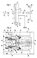
- Fig. 2 shows details of the control valve V2.
- the function of the connections 16, 18 and 20 of the valve has already been explained above.
- the connection 20 serves as an inlet for fluid under relatively high pressure, for example atmospheric air.
- the valve V2 has a housing 30 in which an electromagnet 32 is arranged.
- the armature 34 of the electromagnet 32 is axially movable in a conventional manner along the axis A of the valve.
- the armature 34 of the electromagnet 32 acts in FIG. 2 on the left on a valve piston 36, which is also axially movable.
- a valve piston 36 In the valve piston 36, an inner sleeve 38 is arranged concentrically therewith, which is also axially displaceable within limits.
- a spring 40 presses the inner sleeve 38 and the valve piston 36 in FIG. 2 to the right into the rest position shown. In this rest position, the connections 16 and 18 of the valve are conductively connected to one another, so that when the valve is used in a brake booster according to FIG. 1, both chambers I, II of the brake booster are suctioned.
- the switching of the individual valve paths is explained in more detail below.
- two further springs are provided, namely a spring 42 captured between the valve piston 36 and the inner sleeve 38 and a coaxial one Spring 44, which has a somewhat stronger tensioning force than spring 42. In the state shown in FIG. 2, spring 42 is relaxed.
- a bolt 46 guides the inner sleeve 38 in the valve piston 36 and allows an axial relative movement between these parts.
- the cuff 48 already mentioned is made of elastic material and allows the valve piston 36 to move axially.
- the cuff 48 is designed such that it moves the valve piston 36 into the rest position shown in FIG. 2.
- Another cuff 50 made of elastic material has a valve seat V S on the end face.
- a steel ring 52 is firmly inserted into the sleeve 50 and serves as a stop for the spring 44 and the inner sleeve 38.
- a free space 54 is left between the housing 30 and the sleeve 54 and, accordingly, there is a free space 56 between the valve piston 36 and the housing 30.
- a seat ring 60 is integrally formed on the housing 30, which in the state according to FIG. 2 engages with the valve seat V S. By this engagement of the seat ring 60 with the valve seat V S , the inlet 20 of the valve V2 is shut off, so that no atmospheric air can enter the valve.
- a further seat ring 62 is formed, which, in the state shown in FIG.
- a filter 64 is arranged in front of the inlet 20 of the valve V2.
- valve V2 The function of the valve V2 is as follows. 2, the inlet 20 and the associated circumferential free space 54 are blocked because the valve seat V S is pressed against the seat ring to the right by the spring 44 via the stop 52.
- a flow path runs from the connection 16 of the valve via a free space 66 through a gap between the stop 52 and the inner sleeve 38 and a further gap between the seat rings 60, 62 in the channel 18.
- the seat rings are 60, 62 drawn very closely next to each other, however, air passage is possible between them.
- the armature 34 in FIG. 2 presses to the left on the valve piston 36.
- the valve piston 36 therefore also moves to the left.
- the inner sleeve 38 is also moved to the left by the spring 42 until it abuts the stop 52 with its left end edge.
- the movement of the inner sleeve 38 is interrupted because the spring constant of the spring 42 e.g. 20% smaller than the spring constant of the spring 44.
- the springs 42, 44 are preferably dimensioned such that the captured spring 42 has 5 to 25%, preferably 10 to 25% less spring force than the spring 44 acting on the stop 52 from the left .
- the electromagnet 32 now pushes the valve piston 36 further to the left in FIG. 2 until the cutting edge 62 of the valve piston 36 abuts the valve seat V S.
- the cutting edge 62 presses the valve seat against the force of the spring 44 to the left, so that the valve seat V S lifts off the cutting edge 60 of the housing 30.
- the control of the fluid flow by means of the valve can thus be carried out very sensitively and precisely.
- the valve enables exact dosing and responds almost instantaneously.
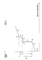
- Fig. 3 shows the functional dependence of the magnetic force of the electromagnet 32 and the path of the valve piston 36 in the opening stroke described above.
- a relatively low magnetic force is sufficient to overcome an idle stroke on path a.
- the tension of the relatively weak return spring 40 must be overcome.
- the slope of curve b corresponds to the spring constant of spring 40.
- the inner sleeve 38 abuts the stop 52.
- the armature 34 of the electromagnet 32 is practically at a standstill until the electromagnet has developed a sufficiently large force to be able to compress the captured spring 42. This is the case at point Y.
- the spring 42 counteracts a further movement of the armature and thus the slope of the curve piece d corresponds to the spring constant of the captured spring 42.
- the seat ring 62 of the valve piston 36 meets the valve seat V S.
- the force difference U shown in FIG. 3 is the force hysteresis that would occur in a valve with a single spring that has to be overcome to open the valve, that is to say a valve not according to the invention, while according to the invention when opening and closing the valve only that relatively small force difference V must be overcome.
- the slope of the associated curve piece e corresponds only to the "residual force" of the spring 44, since its tensioning force has already largely been canceled by the pressed spring 42.
Landscapes
- Physics & Mathematics (AREA)
- Engineering & Computer Science (AREA)
- Fluid Mechanics (AREA)
- Transportation (AREA)
- Mechanical Engineering (AREA)
- Electromagnetism (AREA)
- General Physics & Mathematics (AREA)
- Automation & Control Theory (AREA)
- Valves And Accessory Devices For Braking Systems (AREA)
- Magnetically Actuated Valves (AREA)
- Braking Systems And Boosters (AREA)
Abstract
Ein Ventil zum Steuern eines Differenzdruckes weist einen in einem Gehäuse 30 mittels eines Elektromagneten 32 verschiebbaren Ventilkolben 36 auf. Eine erste Feder 44 drückt über einen Anschlag 52 den Ventilsitz VS in seine Ruhestellung gegen einen ersten Sitzring 60. Der Ventilkolben 36 wird bei einer Bewegung in Richtung auf den Ventilsitz VS vor oder bei seinem Auftreffen auf den Ventilsitz über eine zweite Feder 42 abgefangen. Weil die erste Feder eine etwas größere Spannkraft aufweist als die zweite Feder ist hiermit eine sehr feinfühlige Betätigung des Ventils möglich.
Description
- Die Erfindung betrifft ein Ventil zum Steuern eines Differenzdruckes mit einem Gehäuse, das einen Einlaß für ein unter relativ hohem Druck stehendes Fluid und zumindest einen Auslaß für das Fluid aufweist und in dem ein Ventilkolben mittels eines Elektromagneten axial in Richtung auf einen Ventilsitz verschiebbar ist, der mittels einer ersten Feder in entgegengesetzter Richtung axial vorgespannt ist.
- Insbesondere soll ein solches Ventil zum Steuern eines Bremskraftverstärkers in einer Fahrzeugbremsanlage verwendet werden.
- Aus der DE-OS 37 22 315 ist ein 3/2-Druckregelventil der eingangs genannten Art bekannt, bei dem zwei koaxiale, im Ventilgehäuse verschiebbar gelagerte Ventilglieder vorgesehen sind. Es erfolgt eine Regelung eines Sekundärdruckes in Abhängigkeit von einer Kraft, die auf eines der ventilglieder wirkt und von einem Elektromagneten erzeugt ist. Auf die Ventilglieder wirken Federn und die pneumatisch oder hydraulisch wirksamen Flächen sind so bemessen, daß die Ventilglieder sich in Abhängigkeit von den gewünschten Drücken einstellen.
- Der Erfindung liegt die Aufgabe zugrunde, ein Ventil zum Steuern eines Differenzdruckes zu schaffen, welches einfach und funktionssicher aufgebaut ist, eine sehr exakte Dosierung eines Fluids gestattet und eine lange Lebensdauer besitzt. Das Ventil soll überdies geeignet sein, mit sehr geringen Kräften präzise betätigt zu werden.
- Das erfindungsgemäße Ventil der eingangs genannten Art ist dadurch gekennzeichnet, daß der ventilkolben bei einer Bewegung in Richtung auf den Ventilsitz vor oder bei seinem Auftreffen auf den Ventilsitz über eine zweite Feder in Wirkeingriff kommt mit einem Anschlag, der mit dem Ventilsitz verbunden ist, und daß die erste Feder eine größere Spannkraft hat als die zweite Feder.
- Erfindungsgemäß wird also ein axial bewegbarer Ventilsitz auf der einen Seite von einer ersten Feder beaufschlagt, die den Ventilsitz in seine Ruhelage vorspannt. Auf der anderen Seite ist ein Ventilkolben axial verschiebbar, der bei Betätigung des Ventils mittels eines Elektromagneten (oder einer anderen Stellvorrichtung) in Richtung auf den Ventilsitz bewegt wird. Trifft der Ventilkolben auf den Ventilsitz, so kann er ihn gegen die Kraft der ersten Feder in eine Offenstellung des Ventils abheben. Vor dem Auftreffen des Ventilkolbens auf den Ventilsitz ist aber erfindungsgemäß vorgesehen, daß die Bewegung des Ventilkolbens mittels einer zweiten Feder zunächst abgefangen wird, wobei die zweite Feder schwächer ist als die erste Feder, so daß erst eine erhöhte Kraft des Elektromagneten auf den Ventilkolben einwirken muß, damit dieser den Ventilsitz von einem Dichtring abheben kann.
- Gemäß einer bevorzugten Ausgestaltung des erfindungsgemäßen Ventils ist der Ventilkolben hülsenförmig ausgebildet und umfängt konzentrisch eine innere Hülse, wobei die vorstehend genannte zweite Feder zwischen dem Ventilkolben und der inneren Hülse eingefangen ist. Diese Anordnung ermöglicht einen einfach zu montierenden Aufbau des Ventils.
- Gemäß einer weiteren Ausgestaltung ist vorgesehen, daß der Ventilsitz auf einer Manschette aus elastischem Material ausgebildet ist und daß als Anschlag ein Ring vorgesehen ist.
- Nach einer weiteren bevorzugten Ausgestaltung des erfindungsgemäßen Ventils ist vorgesehen, daß der Ventilsitz gegen einen ersten Sitzring andrückbar ist, wobei ein Strömungsweg vom Einlaß zu einem Auslaß geschlossen wird, und daß am Ventilkolben ein zweiter Sitzring ausgeformt ist, mit dem bei axialer Bewegung des Ventilkolbens der Ventilsitz vom ersten Sitzring abhebbar ist, wobei ein anderer Auslaß abgesperrt wird.
- Der Begriff "Sitzring" im Sinne der Erfindung soll nicht notwendig beinhalten, daß der Ring eine messerscharfe Kante aufweist. Die Kante kann auch abgerundet sein. Wesentlich ist, daß der "Sitzring" auf den elastischen Ventilsitz eindrückbar ist und dabei eine Abdichtung erreicht wird.
- Gemäß einer weiteren bevorzugten Weiterbildung des erfindungsgemäßen Ventils ist der Ventilsitz als ebene Fläche ausgeformt und die Sitzringe sind konzentrisch angeordnet. Dabei liegen die Sitzringe so eng als möglich nebeneinander, weisen also einen nur geringen Unterschied im Durchmesser auf.
- Nachfolgend wird ein Ausführungsbeispiel der Erfindung anhand der Zeichnung näher erläutert. Es zeigt:
- Fig. 1
- schematisch einen Bremskraftverstärker einer Fahrzeugbremsanlage, bei der das erfindungsgemäße Ventil eingesetzt wird,
- Fig. 2
- Einzelheiten des erfindungsgemäßen Ventils in Ruhestellung, und
- Fig. 3
- den Verlauf der Abhängigkeit der am Ventil aufzubringenden Magnetkraft vom Weg des Ventilkolbens.
- Fig. 1 zeigt in schematischer Darstellung ein Bremspedal P, das zum Bremsen in Richtung des Pfeiles bewegt wird. Die vom Bremspedal erzeugte Kraft wird mittels eines Kraftsensors S₁ gemessen. Im Kraftweg 10 hinter dem Kraftsensor S₁ ist ein Bremskraftverstärker 12 angeordnet, der in herkömmlicher Weise zwei Kammern I, II und einen aufgrund einer Druckdifferenz in den Kammern verschiebbaren Kolben K aufweist. Hinter dem Bremskraftverstärker 12 im Kraftweg 10 ist ein weiterer Kraftsensor S₂ angeordnet, mit dem die mittels des Bremskraftverstärkers 12 verstärkte Kraft meßbar ist. Der Kraftweg 10 führt in einen herkömmlichen Hauptbremszylinder HZ, der in bekannter Weise Hydraulikflüssigkeit unter Druck in Bremskreise einspeist. In Fig. 1 ist ein Bremskreis bestehend aus einem Rad HR hinten rechts und einem Rad VL vorne links gezeigt. An den Rädern sind als solche bekannte Drehzahlsensoren SR und SL angeordnet.
- Die Kammer II des Bremskraftverstärkers 12 ist über eine Leitung 14 in bekannter Weise an eine Saugeinrichtung angeschlossen, um in der Kammer II Vakuum zu erzeugen.
- Gemäß Fig. 1 sind zwei Ventile V₁ und V₂ zum Steuern des Bremskraftverstärkers 12 vorgesehen.
- Das Ventil V₁ ist im Kraftweg 10 angeordnet. Es wird mechanisch betätigt, wenn das Bremspedal P gedrückt wird. Insoweit kann das Ventil V₁ von herkömmlicher Bauart sein.
- Zusätzlich ist ein elektromagnetisch betätigbares Ventil V₂ vorgesehen mit zwei Ventilwegen. Dieses elektromagnetisch betätigbare Ventil V₂ ist Gegenstand dieser Erfindung. Ein Ventilweg 16, 18 verbindet die beiden Kammern I und II des Bremskraftverstärkers 12 und ein anderer Ventilweg 18, 20 verbindet die Überdruckkammer I mit einer Fluidquelle, wie z.B. der äußeren Atmosphäre. Die beiden Ventilwege 16, 18 einerseits und 18, 20 andererseits werden alternativ geschaltet, d.h. entweder es werden die beiden Kammern I, II miteinander verbunden, um in beiden Kammern Vakuum anzulegen, oder die Verbindung zwischen den Kammern I, II wird unterbrochen und nur die Kammer I über den Ventilweg 18, 20 mit der äußeren Atmosphäre verbunden.
- Fig. 2 zeigt Einzelheiten des Steuerventils V₂. Die Funktion der Anschlüsse 16, 18 und 20 des Ventils wurde vorstehend bereits erläutert. Der Anschluß 20 dient als Einlaß für unter relativ hohem Druck stehendes Fluid, beispielsweise atmosphärische Luft.
- Das Ventil V₂ weist ein Gehäuse 30 auf, in dem ein Elektromagnet 32 angeordnet ist. Der Anker 34 des Elektromagneten 32 ist in herkömmlicher Weise axial bewegbar entlang der Achse A des Ventils.
- Der Anker 34 des Elektromagneten 32 wirkt in Fig. 2 links auf einen Ventilkolben 36, der ebenfalls axial beweglich ist. Im Ventilkolben 36 ist konzentrisch mit diesem eine innere Hülse 38 angeordnet, die ebenfalls in Grenzen axial verschieblich ist. Eine Feder 40 drückt die innere Hülse 38 sowie den Ventilkolben 36 in Fig. 2 nach rechts in die gezeigte Ruhestellung. In dieser Ruhestellung sind die Anschlüsse 16 und 18 des Ventils leitend miteinander verbunden, so daß bei Anwendung des Ventils bei einem Bremskraftverstärker gemäß Fig. 1 beide Kammern I, II des Bremskraftverstärkers besaugt werden. Die Schaltung der einzelnen Ventilwege wird weiter unten näher erläutert.
- Außer der relativ schwachen Feder 40, welche den Ventilkolben in die Ruhelage bringt (ggf. unterstützt durch eine elastische Manschette 48), sind noch zwei weitere Federn vorgesehen, nämlich eine zwischen dem Ventilkolben 36 und der inneren Hülse 38 eingefangene Feder 42 sowie eine hierzu koaxiale Feder 44, die eine etwas stärkere Spannkraft aufweist als die Feder 42. Im in Fig. 2 gezeigten Zustand ist die Feder 42 entspannt.
- Ein Bolzen 46 führt die innere Hülse 38 im Ventilkolben 36 und erlaubt eine axiale Relativbewegung zwischen diesen Teilen.
- Die bereits erwähnte Manschette 48 ist aus elastischem Material und erlaubt eine axiale Bewegung des Ventilkolbens 36. Die Manschette 48 ist so ausgelegt, daß sie den Ventilkolben 36 in die in Fig. 2 gezeigte Ruhestellung bewegt.
- Eine weitere Manschette 50 aus elastischem Material weist stirnseitig einen Ventilsitz VS auf. In die Manschette 50 fest eingefügt ist ein Stahlring 52, der als Anschlag für die Feder 44 und die innere Hülse 38 dient.
- Zwischen dem Gehäuse 30 und der Manschette 54 ist ein Freiraum 54 gelassen und entsprechend besteht ein Freiraum 56 zwischen dem Ventilkolben 36 und dem Gehäuse 30.
- Am Gehäuse 30 ist integral ein Sitzring 60 ausgebildet, der im Zustand gemäß Fig. 2 in Eingriff mit dem Ventilsitz VS steht. Durch diesen Eingriff des Sitzringes 60 mit dem Ventilsitz VS wird der Einlaß 20 des Ventils V₂ abgesperrt, so daß keine atmosphärische Luft in das Ventil eintreten kann.
- Weiterhin ist auf der dem Ventilsitz VS zugekehrten Stirnseite des Ventilkolbens 36 ein weiterer Sitzring 62 ausgebildet, der im in Fig. 2 gezeigten Zustand noch nicht mit dem Ventilsitz in Eingriff steht.
- Vor dem Einlaß 20 des Ventils V₂ ist ein Filter 64 angeordnet.
- Die Funktion des Ventils V₂ ist wie folgt. Im Ruhezustand gemäß Fig. 2 sind der Einlaß 20 und der zugehörige umlaufende Freiraum 54 abgesperrt, weil der Ventilsitz VS durch die Feder 44 über den Anschlag 52 nach rechts gegen den Sitzring gedrückt ist.
- In diesem Zustand verläuft ein Strömungsweg vom Anschluß 16 des Ventils über einen Freiraum 66 durch eine Lücke zwischen dem Anschlag 52 und der inneren Hülse 38 sowie eine weitere Lücke zwischen den Sitzringen 60, 62 in den Kanal 18. In der Fig. 2 sind die Sitzringe 60, 62 zwar sehr eng nebeneinander gezeichnet, jedoch ist zwischen ihnen ein Luftdurchgang möglich.
- Wird nun der Elektromagnet 32 betätigt, so drückt der Anker 34 in Fig. 2 nach links auf den ventilkolben 36. Der Ventilkolben 36 bewegt sich deshalb ebenfalls nach links. Dabei wird auch die innere Hülse 38 über die Feder 42 nach links bewegt, bis sie mit ihrer linken Stirnkante gegen den Anschlag 52 stößt. Dabei wird zunächst die Bewegung der inneren Hülse 38 unterbrochen, weil die Federkonstante der Feder 42 z.B. 20 % kleiner ist als die Federkonstante der Feder 44. Bevorzugt sind die Federn 42, 44 so bemessen, daß die eingefangene Feder 42 5 bis 25 %, bevorzugt 10 bis 25 % geringere Federkraft aufweist als die von links auf den Anschlag 52 wirkende Feder 44.
- Der Elektromagnet 32 schiebt nun den Ventilkolben 36 in Fig. 2 weiter nach links bis die Schneidkante 62 des Ventilkolbens 36 gegen den Ventilsitz VS stößt. Dabei drückt die Schneidkante 62 den Ventilsitz gegen die Kraft der Feder 44 nach links, so daß der Ventilsitz VS von der Schneidkante 60 des Gehäuses 30 abhebt.
- Steht die Schneidkante 62 des Ventilkolbens 36 mit dem Ventilsitz VS in abdichtendem Eingriff, so ist der Anschluß 16 des Ventils V₂ abgesperrt. Hebt andererseits, wie vorstehend beschrieben, dabei der Ventilsitz VS vom Sitzring 60 ab, so ist ein Strömungsweg geschaffen vom Einlaß 20 über den Freiraum 54 in den weiteren Freiraum 56 und von dort in den Kanal 18. Somit kann das unter Druck stehende Fluid vom Einlaß 20 in den Kanal 18 strömen.
- Die vorstehend beschriebene Anordnung der Federn ermöglicht ein sehr exaktes Steuern des Ventils mit relativ geringen Kräften.
- Durch die eingefangene Feder 42 wird nämlich die Schließwirkung der Feder 44 unmittelbar vor dem Betätigen des Ventils "abgeschwächt". Stößt nämlich die innere Hülse 38 gegen den Anschlag 52, so drückt bereits die eingefangene Feder 42 mit einer Kraft gegen den Anschlag 52 und damit den Ventilsitz VS, die nur um einige Prozent geringer ist als die Spannkraft der Schließfeder 44. Es genügt deshalb im besonders kritischen Bereich der Bewegung des Ventils, in dem eine Öffnung bzw. Schließung desselben erfolgt, eine relativ geringe Kraft zur Ventilbetätigung.
- Somit kann die Steuerung der Fluidströmung mittels des Ventils sehr feinfühlig und exakt erfolgen. Das Ventil ermöglicht eine exakte Dosierung und spricht quasi verzögerungsfrei an.
- Fig. 3 zeigt die funktionale Abhängigkeit der Magnetkraft des Elektromagneten 32 und des Weges des Ventilkolbens 36 bei dem vorstehend beschriebenen Öffnungshub. Zunächst genügt eine relativ geringe Magnetkraft, um auf dem Weg a einen Leerhub zu überwinden. Danach muß die Spannkraft der relativ schwachen Rückführfeder 40 überwunden werden. Die Steigung der Kurve b entspricht der Federkonstanten der Feder 40.
- Am Punkt X stößt die innere Hülse 38 gegen den Anschlag 52. Es herrscht praktisch Stillstand des Ankers 34 des Elektromagneten 32 bis der Elektromagnet eine hinreichend große Kraft entwickelt hat um die eingefangene Feder 42 komprimieren zu können. Dies ist am Punkt Y der Fall. Danach wirkt die Feder 42 einer weiteren Bewegung des Ankers entgegen und somit entspricht die Steigung des Kurvenstückes d der Federkonstanten der eingefangenen Feder 42. Am Punkt Z trifft der Sitzring 62 des Ventilkolbens 36 auf den Ventilsitz VS.
- Danach wirkt am Kurvenstück e die relativ starke Feder 44, weshalb dieses Kurvenstück eine stärkere Steigung aufweist als das Kurvenstück d, welches der etwas schwächeren Feder 42 entspricht.
- Am Punkt O hebt der Ventilsitz VS vom Sitzring ab und das Ventil öffnet.
- Die in Fig. 3 eingezeichnete Kraftdifferenz U ist diejenige Kraft-Hysterese, die bei einem Ventil mit einer einzigen Feder auftreten würde, die zum Öffnen des Ventils überwunden werden muß, also einem nicht erfindungsgemäßen Ventil, während erfindungsgemäß beim Öffnen und Schließen des Ventils nur die relativ geringe Kraftdifferenz V überwunden werden muß. Die Steigung des zugehörigen Kurvenstückes e entspricht nur der "Restkraft" der Feder 44, da deren Spannkraft bereits durch die gedrückte Feder 42 großteils aufgehoben worden ist.
Claims (6)
- Ventil zum Steuern eines Differenzdruckes mit einem Gehäuse (30), das einen Einlaß (20) für ein unter relativ hohem Druck stehendes Fluid und zumindest einen Auslaß (18) für das Fluid aufweist und in dem ein ventilkolben (36) mittels eines Elektromagneten (32) axial in Richtung auf einen Ventilsitz (VS) verschiebbar ist, der mittels einer ersten Feder (44) in entgegengesetzter Richtung axial vorgespannt ist,
dadurch gekennzeichnet,
daß der Ventilkolben (36) bei einer Bewegung in Richtung auf den Ventilsitz (VS) vor oder bei seinem Auftreffen auf den Ventilsitz (VS) über eine zweite Feder (42) in Wirkeingriff kommt mit einem Anschlag (52), der mit dem Ventilsitz (VS) verbunden ist, und daß die erste Feder (44) eine größere Spannkraft hat als die zweite Feder (42). - Ventil nach Anspruch 1,
dadurch gekennzeichnet,
daß der Ventilkolben (36) hülsenförmig ist und konzentrisch eine innere Hülse (38) umfängt und daß die zweite Feder (42) zwischen dem Ventilkolben und der inneren Hülse (38) eingefangen ist. - Ventil nach einem der Ansprüche 1 oder 2,
dadurch gekennzeichnet,
daß der Ventilsitz (VS) auf einer Manschette (50) aus elastischem Material ausgebildet ist und daß als Anschlag (52) ein Ring vorgesehen ist. - Ventil nach einem der vorhergehenden Ansprüche,
dadurch gekennzeichnet,
daß der Ventilsitz (VS) gegen einen ersten Sitzring (60) andrückbar ist, wobei ein Strömungsweg vom Einlaß (20) zu einem Auslaß (18) geschlossen wird, und daß am Ventilkolben (36) ein zweiter Sitzring (62) ausgeformt ist, mit dem bei axialer Bewegung des Ventilkolbens (36) der Ventilsitz (VS) vom ersten Sitzring (60) abhebbar ist, wobei ein anderer Auslaß (16) abgesperrt wird. - Ventil nach Anspruch 4,
dadurch gekennzeichnet,
daß der Ventilsitz (VS) als ebene, radiale Fläche geformt ist und daß die Sitzringe (60, 62) konzentrisch sind sowie einen geringen Unterschied im Durchmesser aufweisen. - Ventil nach einem der vorhergehenden Ansprüche,
dadurch gekennzeichnet,
daß der Ventilkolben (36) mittels einer elastischen Manschette (48) im Gehäuse (30) geführt ist.
Applications Claiming Priority (2)
| Application Number | Priority Date | Filing Date | Title |
|---|---|---|---|
| DE19893943003 DE3943003A1 (de) | 1989-12-27 | 1989-12-27 | Ventil |
| DE3943003 | 1989-12-27 |
Publications (2)
| Publication Number | Publication Date |
|---|---|
| EP0435112A2 true EP0435112A2 (de) | 1991-07-03 |
| EP0435112A3 EP0435112A3 (en) | 1992-09-16 |
Family
ID=6396461
Family Applications (1)
| Application Number | Title | Priority Date | Filing Date |
|---|---|---|---|
| EP19900124247 Withdrawn EP0435112A3 (en) | 1989-12-27 | 1990-12-14 | Valve |
Country Status (6)
| Country | Link |
|---|---|
| US (1) | US5067524A (de) |
| EP (1) | EP0435112A3 (de) |
| JP (1) | JPH03292251A (de) |
| KR (1) | KR910012556A (de) |
| BR (1) | BR9006592A (de) |
| DE (1) | DE3943003A1 (de) |
Cited By (1)
| Publication number | Priority date | Publication date | Assignee | Title |
|---|---|---|---|---|
| WO1999017973A1 (de) * | 1997-10-06 | 1999-04-15 | Lucas Industries Public Limited Company | Elektronisch steuerbarer bremskraftverstärker |
Families Citing this family (10)
| Publication number | Priority date | Publication date | Assignee | Title |
|---|---|---|---|---|
| FR2711104B1 (fr) * | 1993-10-12 | 1996-01-05 | Alliedsignal Europ Services | Système de freinage assisté à commande automatique et à réserve contrôlée. |
| DE19527493A1 (de) * | 1995-07-27 | 1997-01-30 | Lucas Ind Plc | Elektromagnetische Betätigungseinrichtung |
| US5969443A (en) * | 1996-07-15 | 1999-10-19 | Lucas Industries Public Limited Company | Electromagnetic actuating device |
| DE19731417A1 (de) | 1997-07-22 | 1999-01-28 | Itt Mfg Enterprises Inc | Ventileinrichtung |
| US5979503A (en) * | 1997-08-22 | 1999-11-09 | Alliedsignal Truck Brake Systems, Co. | ABS modulator solenoid with a pressure balancing piston |
| DE19812804C2 (de) * | 1998-03-16 | 2002-02-28 | Rexroth Mecman Gmbh | Ventil zur Entlüftung, insbesondere als Bestandteil eines elektropneumatischen Druckregelventils |
| DE19904901A1 (de) | 1999-02-06 | 2000-08-10 | Zahnradfabrik Friedrichshafen | Proportional-Druckregelventil |
| US20050110342A1 (en) * | 2003-11-24 | 2005-05-26 | Eberling Charles E. | Brake actuator with integral antilock modulator |
| KR101303971B1 (ko) * | 2011-04-25 | 2013-09-05 | 최인수 | 플런저 냉각장치를 구비하는 고압력 호모게나이저용 플런저펌프 |
| KR102008824B1 (ko) | 2012-06-21 | 2019-08-08 | 보르그워너 인코퍼레이티드 | 침지형 솔레노이드 밸브 |
Family Cites Families (2)
| Publication number | Priority date | Publication date | Assignee | Title |
|---|---|---|---|---|
| DE3305092A1 (de) * | 1983-02-14 | 1984-08-16 | Herion-Werke Kg, 7012 Fellbach | Druckregelventil |
| DE3722315A1 (de) * | 1987-07-07 | 1989-01-19 | Joucomatic Gmbh | Druckregelventil |
-
1989
- 1989-12-27 DE DE19893943003 patent/DE3943003A1/de not_active Withdrawn
-
1990
- 1990-12-14 EP EP19900124247 patent/EP0435112A3/de not_active Withdrawn
- 1990-12-22 KR KR1019900021412A patent/KR910012556A/ko not_active Withdrawn
- 1990-12-26 BR BR9006592A patent/BR9006592A/pt unknown
- 1990-12-27 US US07/634,559 patent/US5067524A/en not_active Expired - Fee Related
- 1990-12-27 JP JP2408024A patent/JPH03292251A/ja active Pending
Cited By (2)
| Publication number | Priority date | Publication date | Assignee | Title |
|---|---|---|---|---|
| WO1999017973A1 (de) * | 1997-10-06 | 1999-04-15 | Lucas Industries Public Limited Company | Elektronisch steuerbarer bremskraftverstärker |
| US6422123B1 (en) | 1997-10-06 | 2002-07-23 | Lucas Industries Plc | Electronically controllable brake booster |
Also Published As
| Publication number | Publication date |
|---|---|
| KR910012556A (ko) | 1991-08-08 |
| JPH03292251A (ja) | 1991-12-24 |
| US5067524A (en) | 1991-11-26 |
| BR9006592A (pt) | 1991-10-01 |
| DE3943003A1 (de) | 1991-07-04 |
| EP0435112A3 (en) | 1992-09-16 |
Similar Documents
| Publication | Publication Date | Title |
|---|---|---|
| EP0435113B1 (de) | Fahrzeugbremsanlage | |
| DE3337894C2 (de) | ||
| EP1028877A2 (de) | Bremskraftübersetzungseinrichtung insbesondere für kraftfahrzeuge | |
| EP0620789A1 (de) | Unterdruckbremskraftverstärker. | |
| DE69713328T2 (de) | Bremskraftverstärker mit veränderbarer verstärkungsverhaltung | |
| DE69301611T2 (de) | Bremskraftverstärker mit verzögerter hydraulischer reaktion | |
| EP0435112A2 (de) | Ventil | |
| DE3739337A1 (de) | Ventilanordnung | |
| DE3343172C2 (de) | ||
| WO1998041430A1 (de) | Hydraulische, mit fremdkraft betätigbare bremsanlage | |
| EP0386179A1 (de) | Blockiergeschützte kraftfahrzeugbremsanlage. | |
| DE69502407T2 (de) | Pneumatischer bremskraftverstärker | |
| DE3338690A1 (de) | Einrichtung zum steuern des bremsdruckes | |
| EP0589185B1 (de) | Zweikreisige Bremsventileinrichtung | |
| EP0337473A1 (de) | Hydraulische Bremsanlage | |
| DE1922024C3 (de) | Steuerventil, insbesondere für blockiergeschützte Bremsanlagen | |
| EP0752944B1 (de) | Ventilbaugruppe zum steuern eines pneumatischen bremskraftverstärkers mit einer elektromagnetischen betätigungseinrichtung | |
| DE2556923C2 (de) | Steuerventil für eine blockiergeschützte hydraulische Bremsanlage | |
| DE10010385B4 (de) | Unterdruckbremskraftverstärker mit verbesserter magnetloser Notbremshilfe | |
| EP1126998B1 (de) | Unterdruckbremskraftverstärker mit magnetloser notbremshilfe | |
| EP1518773B1 (de) | Anhängersteuerventil für Zugfahrzeug mit elektronisch geregelter Bremsanlage | |
| EP1658213B1 (de) | Betätigungseinheit für eine hydraulische fahrzeugbremse | |
| DE2451554C2 (de) | Unterdruck-Bremskraftverstärker | |
| EP1098800A1 (de) | Hauptzylinder mit verbesserten notbremseigenschaften für eine hydraulische fahrzeugbremsanlage | |
| DE1233289B (de) | Servobremsgeraet, insbesondere fuer Kraftfahrzeuge |
Legal Events
| Date | Code | Title | Description |
|---|---|---|---|
| PUAI | Public reference made under article 153(3) epc to a published international application that has entered the european phase |
Free format text: ORIGINAL CODE: 0009012 |
|
| AK | Designated contracting states |
Kind code of ref document: A2 Designated state(s): DE ES FR GB IT |
|
| PUAL | Search report despatched |
Free format text: ORIGINAL CODE: 0009013 |
|
| AK | Designated contracting states |
Kind code of ref document: A3 Designated state(s): DE ES FR GB IT |
|
| STAA | Information on the status of an ep patent application or granted ep patent |
Free format text: STATUS: THE APPLICATION IS DEEMED TO BE WITHDRAWN |
|
| 18D | Application deemed to be withdrawn |
Effective date: 19930317 |