EP0433892A1 - GestÀ¤ngesystem zum parallelen Bewegen eines an einem Bagger oder einer Grundbaumaschine angebrachten Arbeitsgerätes - Google Patents
GestÀ¤ngesystem zum parallelen Bewegen eines an einem Bagger oder einer Grundbaumaschine angebrachten Arbeitsgerätes Download PDFInfo
- Publication number
- EP0433892A1 EP0433892A1 EP90124091A EP90124091A EP0433892A1 EP 0433892 A1 EP0433892 A1 EP 0433892A1 EP 90124091 A EP90124091 A EP 90124091A EP 90124091 A EP90124091 A EP 90124091A EP 0433892 A1 EP0433892 A1 EP 0433892A1
- Authority
- EP
- European Patent Office
- Prior art keywords
- equipment
- machine
- hinged
- linkage system
- linkage
- Prior art date
- Legal status (The legal status is an assumption and is not a legal conclusion. Google has not performed a legal analysis and makes no representation as to the accuracy of the status listed.)
- Granted
Links
- 239000012530 fluid Substances 0.000 claims description 2
- 238000005553 drilling Methods 0.000 description 3
- 230000004075 alteration Effects 0.000 description 1
- 238000010276 construction Methods 0.000 description 1
- 238000003466 welding Methods 0.000 description 1
Images


Classifications
-
- E—FIXED CONSTRUCTIONS
- E02—HYDRAULIC ENGINEERING; FOUNDATIONS; SOIL SHIFTING
- E02F—DREDGING; SOIL-SHIFTING
- E02F3/00—Dredgers; Soil-shifting machines
- E02F3/04—Dredgers; Soil-shifting machines mechanically-driven
- E02F3/28—Dredgers; Soil-shifting machines mechanically-driven with digging tools mounted on a dipper- or bucket-arm, i.e. there is either one arm or a pair of arms, e.g. dippers, buckets
- E02F3/30—Dredgers; Soil-shifting machines mechanically-driven with digging tools mounted on a dipper- or bucket-arm, i.e. there is either one arm or a pair of arms, e.g. dippers, buckets with a dipper-arm pivoted on a cantilever beam, i.e. boom
- E02F3/302—Dredgers; Soil-shifting machines mechanically-driven with digging tools mounted on a dipper- or bucket-arm, i.e. there is either one arm or a pair of arms, e.g. dippers, buckets with a dipper-arm pivoted on a cantilever beam, i.e. boom with an additional link
-
- E—FIXED CONSTRUCTIONS
- E02—HYDRAULIC ENGINEERING; FOUNDATIONS; SOIL SHIFTING
- E02F—DREDGING; SOIL-SHIFTING
- E02F3/00—Dredgers; Soil-shifting machines
- E02F3/04—Dredgers; Soil-shifting machines mechanically-driven
- E02F3/28—Dredgers; Soil-shifting machines mechanically-driven with digging tools mounted on a dipper- or bucket-arm, i.e. there is either one arm or a pair of arms, e.g. dippers, buckets
- E02F3/30—Dredgers; Soil-shifting machines mechanically-driven with digging tools mounted on a dipper- or bucket-arm, i.e. there is either one arm or a pair of arms, e.g. dippers, buckets with a dipper-arm pivoted on a cantilever beam, i.e. boom
- E02F3/308—Dredgers; Soil-shifting machines mechanically-driven with digging tools mounted on a dipper- or bucket-arm, i.e. there is either one arm or a pair of arms, e.g. dippers, buckets with a dipper-arm pivoted on a cantilever beam, i.e. boom working outwardly
Definitions
- This invention refers to a linkage system for making an equipment translate parallely to itself, such equipment being carried by an exacavator or by a basic machine. More specifically the invention refers to an articulated parallelogram linkage system connecting drilling and other similar equipments with the machine carrying them.
- the mast of the equipment is known to be connected with the machine by means of an articulated linkage system which makes it translate, keeping the equipment consistently parallel to its own original position.
- linkages usually consist of bars, frames and pistons combined in such a way as to keep a constant parallelism of the equipment while the geometry of the linkage changes during the various movements of the equipment.
- Another drawback can be the fact that such a connection can alter the properties of the frame on which it is welded, making it weaker or at least making the original structure less reliable as a whole.
- the purpose of this invention is to obviate the above mentioned drawbacks by proposing a linkage system allowing to keep the structure of new or existing multi-purpose commercial machines unvaried, as two hinging points are sufficient to carry the equipment.
- this invention proposes to realize a linkage system connecting an equipment and an excavator or a basic machine by which such linkage is carried, characterized in that the linkage is quadrilateral so as to translate said equipment parallely to itself; the linkage consisting of at least one rigid connecting element between the machine and the equipment and at least one piston-like actuating element for said rigid element; the elements forming the linkage system or part of them being connected with the machine along no more than two separate and substantially parallel hinge axles.
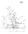
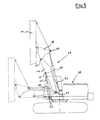
- a basic machine 10 carries a drilling equipment generally indicated by 11, which is moreover connected to the basic machine 10 by means of a linkage 12 that allows the equipment 11 to translate parallely to itself, as shown clearly by the figures.
- Linkage 12 consists of a rigid boom 13, a rigid bar 14 and a piston 15. Boom 13 and bar 14 are hinged respectively in 16 and 17 to a frame 18, which in turn is hinged in 19 to the mast of equipment 11.
- Stem 21 of piston 15 is hinged in an intermediate point 20 of boom 13.
- boom 13 is hinged in 22 to the basic machine 10, while bar 14 and piston 15 are hinged along one hinge axle 23 to the same machine 10.
- FIG. 2 A preferential but not limitative configuration of this hinging system is shown by fig. 2, consisting of two side-mounted bars 14, rigidly joined by a cross-member 24 with respective fork-extensions 25. These have their ends connected to flanges 26 of the machine 10 and to lugs 27 of two side-mounted pistons 15 that pivot on the same shaft through pins 23.
- actuators 40 and 15 of fig. 5 are series connected through an incompressible fluid in such a way that if an actuator , for example 40, is expanded, the second actuator 15 is automatically forced by the first one to expand too, thus generating the parallel motion.
- the pivoting points of unit 12 to machine 10 are realized only along two horizontal axles 22 and 23, which, in the case of an existing machine such as a commercial excavator , are the hinging points provided for the attachment of the equipment that can be mounted on the machine. Consequently, the machine does not require any supplementary adapting parts, such as brackets to be welded on for extra hinge axles.
Landscapes
- Engineering & Computer Science (AREA)
- Mechanical Engineering (AREA)
- Mining & Mineral Resources (AREA)
- Civil Engineering (AREA)
- General Engineering & Computer Science (AREA)
- Structural Engineering (AREA)
- Earth Drilling (AREA)
Applications Claiming Priority (2)
| Application Number | Priority Date | Filing Date | Title |
|---|---|---|---|
| IT05356189U IT222543Z2 (it) | 1989-12-19 | 1989-12-19 | Gruppo cinematico a quadrilatero per la traslazione parallelamente a se stesso di un gruppo attuatore portato da un escavatore o da una macchina base. |
| IT5356189U | 1989-12-19 |
Publications (2)
| Publication Number | Publication Date |
|---|---|
| EP0433892A1 true EP0433892A1 (de) | 1991-06-26 |
| EP0433892B1 EP0433892B1 (de) | 1996-03-06 |
Family
ID=11283696
Family Applications (1)
| Application Number | Title | Priority Date | Filing Date |
|---|---|---|---|
| EP90124091A Expired - Lifetime EP0433892B1 (de) | 1989-12-19 | 1990-12-13 | Gestängesystem zum parallelen Bewegen eines an einem Bagger oder einer Grundbaumaschine angebrachten Arbeitsgerätes |
Country Status (4)
| Country | Link |
|---|---|
| EP (1) | EP0433892B1 (de) |
| DE (1) | DE69025729T2 (de) |
| ES (1) | ES2084640T3 (de) |
| IT (1) | IT222543Z2 (de) |
Cited By (1)
| Publication number | Priority date | Publication date | Assignee | Title |
|---|---|---|---|---|
| US11459826B2 (en) | 2018-01-16 | 2022-10-04 | Soilmec S.P.A. | Assembly for moving excavation or drilling equipment and actuating method therefor |
Citations (3)
| Publication number | Priority date | Publication date | Assignee | Title |
|---|---|---|---|---|
| US4103791A (en) * | 1977-06-03 | 1978-08-01 | Harnischfeger Corporation | Shovel attachment means for hydraulic excavator |
| US4364705A (en) * | 1980-07-07 | 1982-12-21 | J. I. Case Company | Loader mechanism |
| FR2537183A1 (fr) * | 1982-12-06 | 1984-06-08 | Orenstein & Koppel Ag | Fleche de pelle mecanique |
-
1989
- 1989-12-19 IT IT05356189U patent/IT222543Z2/it active IP Right Grant
-
1990
- 1990-12-13 ES ES90124091T patent/ES2084640T3/es not_active Expired - Lifetime
- 1990-12-13 DE DE69025729T patent/DE69025729T2/de not_active Expired - Fee Related
- 1990-12-13 EP EP90124091A patent/EP0433892B1/de not_active Expired - Lifetime
Patent Citations (3)
| Publication number | Priority date | Publication date | Assignee | Title |
|---|---|---|---|---|
| US4103791A (en) * | 1977-06-03 | 1978-08-01 | Harnischfeger Corporation | Shovel attachment means for hydraulic excavator |
| US4364705A (en) * | 1980-07-07 | 1982-12-21 | J. I. Case Company | Loader mechanism |
| FR2537183A1 (fr) * | 1982-12-06 | 1984-06-08 | Orenstein & Koppel Ag | Fleche de pelle mecanique |
Cited By (1)
| Publication number | Priority date | Publication date | Assignee | Title |
|---|---|---|---|---|
| US11459826B2 (en) | 2018-01-16 | 2022-10-04 | Soilmec S.P.A. | Assembly for moving excavation or drilling equipment and actuating method therefor |
Also Published As
| Publication number | Publication date |
|---|---|
| ES2084640T3 (es) | 1996-05-16 |
| IT8953561V0 (it) | 1989-12-19 |
| IT8953561U1 (it) | 1991-06-19 |
| DE69025729T2 (de) | 1996-07-25 |
| EP0433892B1 (de) | 1996-03-06 |
| DE69025729D1 (de) | 1996-04-11 |
| IT222543Z2 (it) | 1995-04-21 |
Similar Documents
| Publication | Publication Date | Title |
|---|---|---|
| US7818901B2 (en) | Progressive linkage for excavator thumb | |
| EP3612683B1 (de) | Laderhubarmanordnung für eine kraftmaschine | |
| US10316488B2 (en) | Universal backhoe coupler | |
| GB2333760A (en) | Method of visibly ensuring quick coupling | |
| EP0478749A1 (de) | Aufreisseranlage mit verstelleinrichtung und einheitlichem schubblock und rahmen. | |
| US4087009A (en) | Backhoe frame | |
| US4486141A (en) | Linkage system for a loader vehicle | |
| DE4208245A1 (de) | Auslegersystem fuer bagger | |
| DE69804798T2 (de) | Rahmenanordnung für eine arbeitsmaschine und damit verbundenes verfahren zur ihrer herstellung | |
| US4337837A (en) | Mounting mechanism for angle dozer blade | |
| US3749182A (en) | Angle and tilt mechanism for bulldozer | |
| US3784162A (en) | Scissor hoist | |
| EP0433892B1 (de) | Gestängesystem zum parallelen Bewegen eines an einem Bagger oder einer Grundbaumaschine angebrachten Arbeitsgerätes | |
| DE69808910T2 (de) | Kippgestängeanordnung | |
| US4113031A (en) | Power shift mechanism for earth working implements | |
| US3452882A (en) | Swing mechanism for backhoes | |
| JP2771121B2 (ja) | 除雪装置 | |
| GB2212132A (en) | Apparatus for a folding-down loader tailboard | |
| DE2357365B2 (de) | Auslegergestänge | |
| US5266001A (en) | Working machine for construction vehicles and method of operating the same | |
| US4725187A (en) | Excavator | |
| US4244429A (en) | Mounting mechanism for angle dozer blade | |
| DE19746702A1 (de) | Schwenkadapter | |
| EP0399043B1 (de) | Verfahren zur verwendung eines gegliederten armes für baufahrzeuge | |
| RU2082854C1 (ru) | Грейфер |
Legal Events
| Date | Code | Title | Description |
|---|---|---|---|
| PUAI | Public reference made under article 153(3) epc to a published international application that has entered the european phase |
Free format text: ORIGINAL CODE: 0009012 |
|
| AK | Designated contracting states |
Kind code of ref document: A1 Designated state(s): BE DE ES FR GB IT NL |
|
| 17P | Request for examination filed |
Effective date: 19911009 |
|
| 17Q | First examination report despatched |
Effective date: 19930730 |
|
| GRAA | (expected) grant |
Free format text: ORIGINAL CODE: 0009210 |
|
| AK | Designated contracting states |
Kind code of ref document: B1 Designated state(s): BE DE ES FR GB IT NL |
|
| REF | Corresponds to: |
Ref document number: 69025729 Country of ref document: DE Date of ref document: 19960411 |
|
| REG | Reference to a national code |
Ref country code: ES Ref legal event code: FG2A Ref document number: 2084640 Country of ref document: ES Kind code of ref document: T3 |
|
| ITF | It: translation for a ep patent filed | ||
| ET | Fr: translation filed | ||
| PLBE | No opposition filed within time limit |
Free format text: ORIGINAL CODE: 0009261 |
|
| STAA | Information on the status of an ep patent application or granted ep patent |
Free format text: STATUS: NO OPPOSITION FILED WITHIN TIME LIMIT |
|
| 26N | No opposition filed | ||
| REG | Reference to a national code |
Ref country code: GB Ref legal event code: IF02 |
|
| PGFP | Annual fee paid to national office [announced via postgrant information from national office to epo] |
Ref country code: IT Payment date: 20071217 Year of fee payment: 18 |
|
| PGFP | Annual fee paid to national office [announced via postgrant information from national office to epo] |
Ref country code: NL Payment date: 20081203 Year of fee payment: 19 |
|
| PGFP | Annual fee paid to national office [announced via postgrant information from national office to epo] |
Ref country code: ES Payment date: 20090120 Year of fee payment: 19 Ref country code: FR Payment date: 20081212 Year of fee payment: 19 |
|
| PGFP | Annual fee paid to national office [announced via postgrant information from national office to epo] |
Ref country code: DE Payment date: 20081211 Year of fee payment: 19 |
|
| PGFP | Annual fee paid to national office [announced via postgrant information from national office to epo] |
Ref country code: GB Payment date: 20081210 Year of fee payment: 19 |
|
| PGFP | Annual fee paid to national office [announced via postgrant information from national office to epo] |
Ref country code: BE Payment date: 20090112 Year of fee payment: 19 |
|
| BERE | Be: lapsed |
Owner name: *SOILMEC S.P.A. Effective date: 20091231 |
|
| REG | Reference to a national code |
Ref country code: NL Ref legal event code: V1 Effective date: 20100701 |
|
| GBPC | Gb: european patent ceased through non-payment of renewal fee |
Effective date: 20091213 |
|
| REG | Reference to a national code |
Ref country code: FR Ref legal event code: ST Effective date: 20100831 |
|
| PG25 | Lapsed in a contracting state [announced via postgrant information from national office to epo] |
Ref country code: FR Free format text: LAPSE BECAUSE OF NON-PAYMENT OF DUE FEES Effective date: 20091231 Ref country code: BE Free format text: LAPSE BECAUSE OF NON-PAYMENT OF DUE FEES Effective date: 20091231 Ref country code: NL Free format text: LAPSE BECAUSE OF NON-PAYMENT OF DUE FEES Effective date: 20100701 |
|
| PG25 | Lapsed in a contracting state [announced via postgrant information from national office to epo] |
Ref country code: DE Free format text: LAPSE BECAUSE OF NON-PAYMENT OF DUE FEES Effective date: 20100701 |
|
| PG25 | Lapsed in a contracting state [announced via postgrant information from national office to epo] |
Ref country code: GB Free format text: LAPSE BECAUSE OF NON-PAYMENT OF DUE FEES Effective date: 20091213 |
|
| REG | Reference to a national code |
Ref country code: ES Ref legal event code: FD2A Effective date: 20110228 |
|
| PG25 | Lapsed in a contracting state [announced via postgrant information from national office to epo] |
Ref country code: ES Free format text: LAPSE BECAUSE OF EXPIRATION OF PROTECTION Effective date: 20101214 |
|
| PG25 | Lapsed in a contracting state [announced via postgrant information from national office to epo] |
Ref country code: IT Free format text: LAPSE BECAUSE OF NON-PAYMENT OF DUE FEES Effective date: 20081213 |
|
| PG25 | Lapsed in a contracting state [announced via postgrant information from national office to epo] |
Ref country code: ES Free format text: LAPSE BECAUSE OF EXPIRATION OF PROTECTION Effective date: 20091214 |