EP0433869B1 - Precast wall with thermic regulation elements - Google Patents
Precast wall with thermic regulation elements Download PDFInfo
- Publication number
- EP0433869B1 EP0433869B1 EP90123974A EP90123974A EP0433869B1 EP 0433869 B1 EP0433869 B1 EP 0433869B1 EP 90123974 A EP90123974 A EP 90123974A EP 90123974 A EP90123974 A EP 90123974A EP 0433869 B1 EP0433869 B1 EP 0433869B1
- Authority
- EP
- European Patent Office
- Prior art keywords
- wall
- circuit
- bulges
- elements
- heat
- Prior art date
- Legal status (The legal status is an assumption and is not a legal conclusion. Google has not performed a legal analysis and makes no representation as to the accuracy of the status listed.)
- Expired - Lifetime
Links
Images

Classifications
-
- F—MECHANICAL ENGINEERING; LIGHTING; HEATING; WEAPONS; BLASTING
- F24—HEATING; RANGES; VENTILATING
- F24D—DOMESTIC- OR SPACE-HEATING SYSTEMS, e.g. CENTRAL HEATING SYSTEMS; DOMESTIC HOT-WATER SUPPLY SYSTEMS; ELEMENTS OR COMPONENTS THEREFOR
- F24D3/00—Hot-water central heating systems
- F24D3/12—Tube and panel arrangements for ceiling, wall, or underfloor heating
- F24D3/14—Tube and panel arrangements for ceiling, wall, or underfloor heating incorporated in a ceiling, wall or floor
- F24D3/147—Tube and panel arrangements for ceiling, wall, or underfloor heating incorporated in a ceiling, wall or floor arranged in facades
-
- F—MECHANICAL ENGINEERING; LIGHTING; HEATING; WEAPONS; BLASTING
- F24—HEATING; RANGES; VENTILATING
- F24D—DOMESTIC- OR SPACE-HEATING SYSTEMS, e.g. CENTRAL HEATING SYSTEMS; DOMESTIC HOT-WATER SUPPLY SYSTEMS; ELEMENTS OR COMPONENTS THEREFOR
- F24D11/00—Central heating systems using heat accumulated in storage masses
- F24D11/02—Central heating systems using heat accumulated in storage masses using heat pumps
- F24D11/0214—Central heating systems using heat accumulated in storage masses using heat pumps water heating system
- F24D11/0221—Central heating systems using heat accumulated in storage masses using heat pumps water heating system combined with solar energy
-
- Y—GENERAL TAGGING OF NEW TECHNOLOGICAL DEVELOPMENTS; GENERAL TAGGING OF CROSS-SECTIONAL TECHNOLOGIES SPANNING OVER SEVERAL SECTIONS OF THE IPC; TECHNICAL SUBJECTS COVERED BY FORMER USPC CROSS-REFERENCE ART COLLECTIONS [XRACs] AND DIGESTS
- Y02—TECHNOLOGIES OR APPLICATIONS FOR MITIGATION OR ADAPTATION AGAINST CLIMATE CHANGE
- Y02B—CLIMATE CHANGE MITIGATION TECHNOLOGIES RELATED TO BUILDINGS, e.g. HOUSING, HOUSE APPLIANCES OR RELATED END-USER APPLICATIONS
- Y02B10/00—Integration of renewable energy sources in buildings
- Y02B10/20—Solar thermal
-
- Y—GENERAL TAGGING OF NEW TECHNOLOGICAL DEVELOPMENTS; GENERAL TAGGING OF CROSS-SECTIONAL TECHNOLOGIES SPANNING OVER SEVERAL SECTIONS OF THE IPC; TECHNICAL SUBJECTS COVERED BY FORMER USPC CROSS-REFERENCE ART COLLECTIONS [XRACs] AND DIGESTS
- Y02—TECHNOLOGIES OR APPLICATIONS FOR MITIGATION OR ADAPTATION AGAINST CLIMATE CHANGE
- Y02B—CLIMATE CHANGE MITIGATION TECHNOLOGIES RELATED TO BUILDINGS, e.g. HOUSING, HOUSE APPLIANCES OR RELATED END-USER APPLICATIONS
- Y02B10/00—Integration of renewable energy sources in buildings
- Y02B10/70—Hybrid systems, e.g. uninterruptible or back-up power supplies integrating renewable energies
-
- Y—GENERAL TAGGING OF NEW TECHNOLOGICAL DEVELOPMENTS; GENERAL TAGGING OF CROSS-SECTIONAL TECHNOLOGIES SPANNING OVER SEVERAL SECTIONS OF THE IPC; TECHNICAL SUBJECTS COVERED BY FORMER USPC CROSS-REFERENCE ART COLLECTIONS [XRACs] AND DIGESTS
- Y02—TECHNOLOGIES OR APPLICATIONS FOR MITIGATION OR ADAPTATION AGAINST CLIMATE CHANGE
- Y02B—CLIMATE CHANGE MITIGATION TECHNOLOGIES RELATED TO BUILDINGS, e.g. HOUSING, HOUSE APPLIANCES OR RELATED END-USER APPLICATIONS
- Y02B30/00—Energy efficient heating, ventilation or air conditioning [HVAC]
Definitions
- This invention relates to a reinforced concrete wall according to the first part of claims 1 and 3.
- U.S. Patent No. 2,559,198 to Ogden discloses a prefabricated section of a floor equipped with suitable tubes for the circulation of a heating or cooling medium.
- the tubes are embedded into the sections.
- U.S. Patent No. 4,257,481 to Dobson discloses a concrete element having pipes embedded therein as conduits for water.
- U.S. Patent No. 4,285,332 to McHugh discloses a building having a solar heating system integrated in the architecture of the building.
- the invention provides a prefabricated structural wall in which an efficient allocation is made between the elements embedded in the prefabricated structural member and the elements which may be installed within the prefabricated structural member after the latter has been put into place.
- the invention concerns a reinforced concrete wall, either normal or lightweight, either exterior or interior, having embedded therein channels for the accommodation of a circuit which carries water warmed by solar panels and also having embedded therein heat accumulation elements full of water whose temperature is regulated by the circuit, there being suitable coupling between the circuit and the heat accumulation elements.
- Walls of every kind receive heat passively, either by adduction or by radiation, and are always exposed to water-vapor condensation.
- reinforced concrete walls, particularly those with exterior insulation, either aired or not have been designed so that, when installed, they dissipate less heat, consume less power, and maintain interior comfort at acceptable levels.
- the bulk necessary for good heat accumulation and the high costs for the insulation itself and the strata finishing are among the disadvantages of such constructions.
- An object of the present invention is to produce a wall which is light and, although expensive, is able to help the heating system to obtain an economic power consumption and a better level of interior comfort.
- the wall of the present invention can regulate its surface temperature and its heat accumulation. Finally, this accumulation of heat serves to eliminate water-vapor condensation in the exterior walls.
- Claims 2 and 4 to 7 refer to preferred realizations of the reinforced concrete wall.
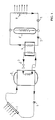
- Fig. 1 is a simplified sketch of a low temperature solar panel circuit which includes the following known elements: a solar panel 1, a first accumulator tank 2, a heat pump 3, a second accumulator tank 4, and a sanitary water unit 5.
- a pump 6 circulates water between the solar panel 1 and the accumulator tank 2.
- the solar panel 1 heats the water passing therethrough to a temperature of about 30°C.
- This heated water is pumped into the first accumulator tank 2 by the pump 6, so that the water in the first accumulator tank 2 is maintained at about 30°C.
- the heat pump 3 then circulates its fluid between the first accumulator tank 2 and the second accumulator tank 4, so as to maintain a temperature of about 50°C in the second accumulator tank 4.
- a pump 7 circulates water between the second accumulator tank 4 and the sanitary water unit 5. The water traveling through the sanitary water unit 5 is thus warmed by passing through the second accumulator tank 4.
- sanitary water unit 5 parallel to the sanitary water unit 5 is another circuit 8 which distributes the wall-warming water through a valve 9.
- the coupling of a heat pump with low temperature solar panels allows the system to work at peak efficiency (i.e. with low power consumption) when the pump covers a small difference in temperature in periods of high solar heating. In periods of low solar heating and at nighttime the pump can still work, though at a low efficiency level, to provide the necessary heat. It follows that the interior surface temperature, which is related to the temperature of the water in the wall circuit 8, can be maintained at an acceptable level of interior comfort independently of the heating system used in the house.
- the circuit 8 includes a multiplicity of conduits arranged within the walls of the building. These conduits convey water which has been heated by the heat pump to the lower part of the interior of the prefabricated walls of the building.
- heat accumulation within the walls is provided by separate components: namely, a multiplicity of heat accumulator elements which are filled with water and sealed off. Heat is delivered from the circuit 8 to the water in the heat accumulator elements by thermal conduction through thin membranes separating the water in the heat accumulator elements from the water in the circuit 8. Since the heat accumulator elements are sealed, means are provided to compensate for thermal expansion and contraction, which results from freezing of the water therein.
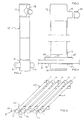
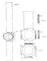
- Fig. 2 shows an individual heat accumulation element 10. It is preferably made of a normal plastic pipe welded at the ends with two fibroreinforced plastic components 17, 18.
- the upper component 17 is shown in Fig. 3 and has a cylindrical bulge 19 grafted onto its lateral surface through which water may flow when the element 10 is initially filled with water. After filling, the bulge 19 is sealed with a top 20.
- the lower component 18 is shown in Fig. 4 and has two cylindrical bulges 21, 22 grafted onto its lateral surface.
- a metallic dissipator 23 is supported within the bulges 21, 22 through two seals 24, 25 which absorb any pipe deformations.
- the airspace at the top of the element may be of any suitable dimension, preferably at least one centimeter.
- the metallic dissipator 23 constitutes one of the membranes which separates the water in the circuit 8 from the water in the heat accumulator elements 10.
- Many of the various conduits which make up the circuit 8 are constructed so as to pass through the cylinders formed by the metallic dissipators 23.
- the outer surface of these conduits of the circuit 8 are close to the inner surface of the cylinders of the metallic dissipators 23.
- Heat from the warm water in the conduit passes by radiation or convection to the water within the heat accumulator element, passing through the metal membranes (namely, the wall of the conduit 8 and the metal dissipator 23).
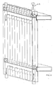
- Fig. 5 shows a plurality of heat accumulation elements 10 before the casting of the wall. These elements are held in place by racks 27 made of concrete.
- the upper bulges 19 facilitate water intake when the heat accumulation elements 10 are initially filled with water.
- the lower bulges 21, 22 are positioned so as to align the metallic dissipators 23 therein so as to receive a conduit of the circuit 8.
- each lower bulge 22 may be in contact with the lower bulge 21 of a neighboring heat accumulation element 10, and leakage of concrete between adjacent bulges 22, 21 may be prevented by use of a suitable tape 41.
- the sequence of bulges 21, 22 forms a horizontal channel adapted to receive a conduit of the circuit 8.
- the heat captured in the solar panels 1 passes from the circuit 8 to the dissipator 23, which in turn heats the water in contact with it.
- the resultant temperature gradient between the heated bottoms of the elements 10 and the tops thereof results in a motion of the water in the elements 10 which distributes the heat throughout these elements; then the heat conduction through the concrete and the surface radiation carries the heat to the exterior.
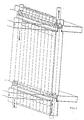
- Fig. 6 shows an exterior wall and Fig. 7 an interior wall in place with the heat accumulation elements in evidence. Both figures show the vertical assembling continuity which, in the exterior wall, eliminates the wall-floor thermic connection. They also illustrate the horizontal and vertical channels for the circuit 8 of Fig. 1.
- the horizontal channels formed by the lower bulges 21, 22, are adapted to receive horizontal metallic heat dissipator pipes 28.
- the vertical channels 40 are adapted to receive vertical plastic adducent pipes 29.
- the vertical channels are aligned by superimposition of the element shown in Fig. 8.
- Fig. 8 is an assembly of a normal plastic pipe (acting as a vertical channel) with a special connector 30 made of fibroreinforced plastic.
- This connector is characterized by four cylindrical bulges 31, 32, 33, 34 grafted onto its lateral surface so as to define two orthogonal transverse axes and by two bulges 35, 36 grafted onto the two end surfaces.
- the four cylindrical bulges 31, 32, 33, 34 are equipped with threading to allow the attachment of either a sealing plug 37 or a reduction plug 38.
- FIG. 13 therein are shown several wall elements constructed according to the invention and arranged as they would be assembled in a building.
- Each wall element contains within it a set of heat accumulator elements aligned so that their lower bulges are in alignment so as to form a horizontal channel through the wall.
- Each heat accumulator element is sealed with a suitable amount of water within it.
- Some of the wall elements also have within them one or more vertical channels 40, and these are provided with the special connector elements of Fig. 8.
- the outermost bulges 21, 22 in each wall element fits into a reduction plug 38 of a connector 30.
- the horizontal conduits may be inserted as shown by the horizontal arrows.
- Horizontal conduits are inserted through the reduction plugs affixed to the ends of the horizontal channels, which are screwed on prior to insertion of the horizontal conduits.
- the horizontal conduits are positioned approximately centrally in the aligned bulges, and may easily be inserted.
- the vertical conduits may be inserted in the vertical channels 40, there being a plurality of vertical conduits in each vertical channel 40, so that water may flow therethrough upwardly in some conduits and downwardly in other conduits, as shown by the vertical arrows. Connections among all the conduits are made by conventional plumbing fixtures, and the connecting operations are performed through the outer apertures in the special connector of Fig. 8. These outer apertures may be positioned so as to protrude from the wall element at the time of casting the concrete, or else they may be affixed to a length of vertical channel 40 which itself protrudes from the wall element at the time of casting the concrete.
- the preferred position for the special connector 30 is at the bottom of its wall element 39, near a corner thereof.
- the four lateral bulges 31, 32, 33, 34 at least one of the interior bulges will have a reduction plug 38 inserted therein to align and position the horizontal metallic heat dissipator pipe 28.
- the two interior bulges will be so equipped.
- the two exterior bulges will remain open so that suitable plumbing connections may be made between the ends of the horizontal dissipator pipes 28 and the vertical adducent pipes 29.
- the two exterior bulges may be closed by suitable sealing plugs 37.
- one may be connected to the vertical channel 40 and embedded therewith in the concrete of the wall element 39.
- the other may communicate with the exterior of the wall element 39 for connection to the vertical channel 40 of the wall element just below. This connection may be made by simple juxtaposition of the vertical channels, since each is merely a housing for the plastic adducent pipes 29 of the circuit 8.
- Fig. 12 is a horizontal plan view, and shows that a wall element (such as that shown at 42) with heat accumulator elements need not connect to other wall elements; it is only necessary that a horizontal conduit pass through the bases of the heat accumulator elements.
- a wall element such as that shown at 42
- heat accumulator elements need not connect to other wall elements; it is only necessary that a horizontal conduit pass through the bases of the heat accumulator elements.
- the horizontal conduits are below the level of the floor.
- each wall element 39 should be at least 25 cm., as indicated in Fig. 14.
Landscapes
- Engineering & Computer Science (AREA)
- Physics & Mathematics (AREA)
- Thermal Sciences (AREA)
- Chemical & Material Sciences (AREA)
- Combustion & Propulsion (AREA)
- Mechanical Engineering (AREA)
- General Engineering & Computer Science (AREA)
- Life Sciences & Earth Sciences (AREA)
- Sustainable Development (AREA)
- Sustainable Energy (AREA)
- Building Environments (AREA)
- Steam Or Hot-Water Central Heating Systems (AREA)
Applications Claiming Priority (2)
| Application Number | Priority Date | Filing Date | Title |
|---|---|---|---|
| IT8948673A IT8948673A0 (it) | 1989-12-19 | 1989-12-19 | Parete prefabbricata termoregolabile. |
| IT4867389 | 1989-12-19 |
Publications (2)
| Publication Number | Publication Date |
|---|---|
| EP0433869A1 EP0433869A1 (en) | 1991-06-26 |
| EP0433869B1 true EP0433869B1 (en) | 1993-07-21 |
Family
ID=11267974
Family Applications (1)
| Application Number | Title | Priority Date | Filing Date |
|---|---|---|---|
| EP90123974A Expired - Lifetime EP0433869B1 (en) | 1989-12-19 | 1990-12-12 | Precast wall with thermic regulation elements |
Country Status (5)
| Country | Link |
|---|---|
| US (1) | US5060718A (it) |
| EP (1) | EP0433869B1 (it) |
| DE (1) | DE69002314T2 (it) |
| ES (1) | ES2043224T3 (it) |
| IT (1) | IT8948673A0 (it) |
Families Citing this family (10)
| Publication number | Priority date | Publication date | Assignee | Title |
|---|---|---|---|---|
| AU1365997A (en) * | 1995-12-22 | 1997-07-17 | Nordisk Vvs Teknik Aps | Solar heat plant |
| US5689838A (en) * | 1996-06-28 | 1997-11-25 | Mackenzie; Andrew R. | Lowering apparatus for toilet seat and toilet seat covers |
| GB9817390D0 (en) * | 1998-08-10 | 1998-10-07 | Warmafloor Gb Ltd | Environmental control system |
| NL1015407C2 (nl) * | 2000-06-09 | 2001-12-19 | Ra Milieutechniek B V | Gebouw met verwarmingsinrichting. |
| DE10109122A1 (de) * | 2001-02-24 | 2002-09-05 | Michael Wawer | Heizsystem zum Beheizen von Räumen |
| US20100198414A1 (en) * | 2007-06-28 | 2010-08-05 | Kroll Steven C | Systems and methods for controlling interior climates |
| US20090001185A1 (en) * | 2007-06-28 | 2009-01-01 | Corvid Homes | Structural wall panels and methods and systems for controlling interior climates |
| CN103221620B (zh) * | 2010-09-17 | 2016-10-12 | 尔班依塔斯有限公司 | 具有热质量辐射体的复合建筑物模块 |
| CN102865615A (zh) * | 2012-09-03 | 2013-01-09 | 中国科学院电工研究所 | 一种利用混凝土储热的太阳能采暖系统 |
| FR3032031B1 (fr) * | 2015-01-26 | 2017-01-27 | Valeo Systemes Thermiques | Batterie thermique a materiau a changement de phase encapsule. |
Family Cites Families (6)
| Publication number | Priority date | Publication date | Assignee | Title |
|---|---|---|---|---|
| DE2026674A1 (de) * | 1970-06-01 | 1971-12-09 | Huebner A | Fußbodenspeicherheizung |
| US4250958A (en) * | 1979-07-16 | 1981-02-17 | Wasserman Kurt J | Double tubular thermal energy storage element |
| JPS595809B2 (ja) * | 1980-08-19 | 1984-02-07 | 守弘 斉藤 | 太陽熱温水器付ブロック壁 |
| US4442826A (en) * | 1980-11-04 | 1984-04-17 | Pleasants Frank M | Prefabricated panel for building construction and method of manufacturing |
| DE3217905A1 (de) * | 1982-05-12 | 1983-06-23 | Hans-Uwe Dipl.-Ing. 8104 Grainau Tiedtke | Niedertemperatur-speicherheizung |
| US4545364A (en) * | 1982-12-20 | 1985-10-08 | One Design, Inc. | Solar heating module |
-
1989
- 1989-12-19 IT IT8948673A patent/IT8948673A0/it unknown
-
1990
- 1990-09-24 US US07/586,820 patent/US5060718A/en not_active Expired - Fee Related
- 1990-12-12 EP EP90123974A patent/EP0433869B1/en not_active Expired - Lifetime
- 1990-12-12 DE DE90123974T patent/DE69002314T2/de not_active Expired - Fee Related
- 1990-12-12 ES ES90123974T patent/ES2043224T3/es not_active Expired - Lifetime
Also Published As
| Publication number | Publication date |
|---|---|
| ES2043224T3 (es) | 1993-12-16 |
| IT8948673A0 (it) | 1989-12-19 |
| EP0433869A1 (en) | 1991-06-26 |
| DE69002314D1 (de) | 1993-08-26 |
| DE69002314T2 (de) | 1994-02-03 |
| US5060718A (en) | 1991-10-29 |
Similar Documents
| Publication | Publication Date | Title |
|---|---|---|
| US4261330A (en) | Solar heat collector | |
| US8985097B2 (en) | Building-integrated solar thermal micro-channel absorber and method of manufacturing thereof | |
| US5048507A (en) | Endothermic building | |
| EP0433869B1 (en) | Precast wall with thermic regulation elements | |
| US8353286B2 (en) | Solar water heater and method | |
| SK29098A3 (en) | Energy system for buildings | |
| WO2009006343A1 (en) | Structural wall panels and methods and systems for controlling interior climates | |
| US4120288A (en) | Solar collector | |
| US10066840B2 (en) | Solar thermal collector system and method configured for radiant cooling | |
| US4442826A (en) | Prefabricated panel for building construction and method of manufacturing | |
| WO2010083834A2 (en) | A building element | |
| GB2023809A (en) | Solar collector apparatus | |
| US4207865A (en) | Passive solar heating device | |
| US5566525A (en) | Method of erecting walls, and form elements therefor | |
| US4426998A (en) | Solar collector unit for roof or wall mounting | |
| CN213089895U (zh) | 一种拼装式地暖盘管结构 | |
| US4349070A (en) | Tube mat heat exchanger | |
| EP1134512B1 (en) | Constructional element | |
| CN214885877U (zh) | 保温隔热型板房 | |
| CN212901727U (zh) | 一种地暖管铺设模块 | |
| GB2622876A (en) | A method of installing a heat transfer panel | |
| SU1483200A1 (ru) | Система солнечного теплоснабжени | |
| KR100446263B1 (ko) | 저온 열기순환 식 온돌난방 | |
| JP3102525B2 (ja) | 鋼管柱列土留壁を利用した空気調和設備用蓄熱装置 | |
| GB1576717A (en) | Solar radiation collectors |
Legal Events
| Date | Code | Title | Description |
|---|---|---|---|
| PUAI | Public reference made under article 153(3) epc to a published international application that has entered the european phase |
Free format text: ORIGINAL CODE: 0009012 |
|
| AK | Designated contracting states |
Kind code of ref document: A1 Designated state(s): DE DK ES FR IT SE |
|
| 17P | Request for examination filed |
Effective date: 19910711 |
|
| 17Q | First examination report despatched |
Effective date: 19911015 |
|
| RAP1 | Party data changed (applicant data changed or rights of an application transferred) |
Owner name: CAPILLI, SERGIO Owner name: CAPILLI, ANNA DOMENICA |
|
| GRAA | (expected) grant |
Free format text: ORIGINAL CODE: 0009210 |
|
| AK | Designated contracting states |
Kind code of ref document: B1 Designated state(s): DE DK ES FR IT SE |
|
| PG25 | Lapsed in a contracting state [announced via postgrant information from national office to epo] |
Ref country code: IT Free format text: LAPSE BECAUSE OF FAILURE TO SUBMIT A TRANSLATION OF THE DESCRIPTION OR TO PAY THE FEE WITHIN THE PRESCRIBED TIME-LIMIT;WARNING: LAPSES OF ITALIAN PATENTS WITH EFFECTIVE DATE BEFORE 2007 MAY HAVE OCCURRED AT ANY TIME BEFORE 2007. THE CORRECT EFFECTIVE DATE MAY BE DIFFERENT FROM THE ONE RECORDED. Effective date: 19930721 Ref country code: DK Effective date: 19930721 Ref country code: SE Effective date: 19930721 |
|
| REF | Corresponds to: |
Ref document number: 69002314 Country of ref document: DE Date of ref document: 19930826 |
|
| ET | Fr: translation filed | ||
| REG | Reference to a national code |
Ref country code: ES Ref legal event code: FG2A Ref document number: 2043224 Country of ref document: ES Kind code of ref document: T3 |
|
| PGFP | Annual fee paid to national office [announced via postgrant information from national office to epo] |
Ref country code: ES Payment date: 19931220 Year of fee payment: 4 |
|
| PGFP | Annual fee paid to national office [announced via postgrant information from national office to epo] |
Ref country code: FR Payment date: 19931230 Year of fee payment: 4 |
|
| PGFP | Annual fee paid to national office [announced via postgrant information from national office to epo] |
Ref country code: DE Payment date: 19940225 Year of fee payment: 4 |
|
| PLBE | No opposition filed within time limit |
Free format text: ORIGINAL CODE: 0009261 |
|
| STAA | Information on the status of an ep patent application or granted ep patent |
Free format text: STATUS: NO OPPOSITION FILED WITHIN TIME LIMIT |
|
| 26N | No opposition filed | ||
| PG25 | Lapsed in a contracting state [announced via postgrant information from national office to epo] |
Ref country code: FR Effective date: 19950831 |
|
| PG25 | Lapsed in a contracting state [announced via postgrant information from national office to epo] |
Ref country code: DE Effective date: 19950901 |
|
| REG | Reference to a national code |
Ref country code: FR Ref legal event code: ST |
|
| PG25 | Lapsed in a contracting state [announced via postgrant information from national office to epo] |
Ref country code: ES Free format text: LAPSE BECAUSE OF NON-PAYMENT OF DUE FEES Effective date: 19951213 |
|
| REG | Reference to a national code |
Ref country code: ES Ref legal event code: FD2A Effective date: 19960113 |