EP0432026B1 - Niederspannungsverbinder für eine Zündspule, insbesondere für Brennkraftmaschine eines Kraftfahrzeuges - Google Patents
Niederspannungsverbinder für eine Zündspule, insbesondere für Brennkraftmaschine eines Kraftfahrzeuges Download PDFInfo
- Publication number
- EP0432026B1 EP0432026B1 EP90403425A EP90403425A EP0432026B1 EP 0432026 B1 EP0432026 B1 EP 0432026B1 EP 90403425 A EP90403425 A EP 90403425A EP 90403425 A EP90403425 A EP 90403425A EP 0432026 B1 EP0432026 B1 EP 0432026B1
- Authority
- EP
- European Patent Office
- Prior art keywords
- primary
- ignition coil
- coil according
- winding spool
- strips
- Prior art date
- Legal status (The legal status is an assumption and is not a legal conclusion. Google has not performed a legal analysis and makes no representation as to the accuracy of the status listed.)
- Expired - Lifetime
Links
- 238000002485 combustion reaction Methods 0.000 title claims description 4
- 238000004804 winding Methods 0.000 claims description 39
- 230000004907 flux Effects 0.000 claims description 3
- 230000000712 assembly Effects 0.000 description 4
- 238000000429 assembly Methods 0.000 description 4
- 239000000463 material Substances 0.000 description 4
- 238000000465 moulding Methods 0.000 description 3
- 239000004033 plastic Substances 0.000 description 3
- 210000002105 tongue Anatomy 0.000 description 3
- 238000005452 bending Methods 0.000 description 2
- 239000002184 metal Substances 0.000 description 2
- 238000003466 welding Methods 0.000 description 2
- 239000004020 conductor Substances 0.000 description 1
- 238000010891 electric arc Methods 0.000 description 1
- 238000000605 extraction Methods 0.000 description 1
- 238000003780 insertion Methods 0.000 description 1
- 230000037431 insertion Effects 0.000 description 1
- 238000009434 installation Methods 0.000 description 1
- 239000011810 insulating material Substances 0.000 description 1
- 238000004519 manufacturing process Methods 0.000 description 1
- 239000000203 mixture Substances 0.000 description 1
- 239000002991 molded plastic Substances 0.000 description 1
- 230000001590 oxidative effect Effects 0.000 description 1
- 230000003071 parasitic effect Effects 0.000 description 1
- 238000005476 soldering Methods 0.000 description 1
- 229920003002 synthetic resin Polymers 0.000 description 1
- 239000000057 synthetic resin Substances 0.000 description 1
Images


Classifications
-
- H—ELECTRICITY
- H01—ELECTRIC ELEMENTS
- H01F—MAGNETS; INDUCTANCES; TRANSFORMERS; SELECTION OF MATERIALS FOR THEIR MAGNETIC PROPERTIES
- H01F38/00—Adaptations of transformers or inductances for specific applications or functions
- H01F38/12—Ignition, e.g. for IC engines
-
- H—ELECTRICITY
- H01—ELECTRIC ELEMENTS
- H01F—MAGNETS; INDUCTANCES; TRANSFORMERS; SELECTION OF MATERIALS FOR THEIR MAGNETIC PROPERTIES
- H01F5/00—Coils
- H01F5/04—Arrangements of electric connections to coils, e.g. leads
Definitions
- the present invention relates to an ignition coil, in particular for an internal combustion engine of a motor vehicle.
- the secondary of such a coil produces a very high voltage making it possible to generate an electric arc at the electrodes of the spark plugs, thus igniting the oxidizing mixture contained in the cylinders of the engine.
- a single coil controls all of the spark plugs via, for example, a mechanical distributor, generally of the rotating finger type.
- the present invention relates more particularly to such a coil, known as a single-cylinder which comprises, in a manner known per se, a closed circuit magnetic assembly comprising a central magnetic core around which two coils of plastic material carrying the primary and secondary windings are arranged coaxially, this assembly being integrated in a molded plastic housing. Synthetic resin, poured inside the case and electrically insulates the different elements of the ignition coil from each other.
- Low-voltage connection devices are generally located on the upper part of the coil assembly and are made up of connection bars, one end of which is connected to the primary winding by welding or any other means and the other end is housed in the body of a connector.
- This connector is fixed to the body of the coil and provides the low-voltage electrical connection with the outside of the latter.
- this connector Depending on the vehicle on which the ignition coil is installed, it is necessary for this connector to have different angular orientations, or even different shapes, in particular to satisfy the space requirements specific to the vehicle. It is therefore necessary for the manufacturer of the ignition coil to deliver his product with different connectors.
- connection bars and the ends, in particular of the primary winding, must be made before introduction of the magnetic assembly of the housing.
- an ignition coil in particular for an internal combustion engine of a motor vehicle, comprising integrated into a housing a magnetic assembly consisting in particular of a magnetic core housed in a primary coil, a coaxial secondary coil. at the primary coil, primary and secondary windings, a magnetic flux return circuit, low-voltage supply means comprising in particular a connector in which bars are overmolded, said bars having ends external to the connector, means for holding the magnetic assembly of the connector and bars, characterized in that the holding means consist of the ends of the bars cooperating with housings formed in a flange of the secondary winding.
- the ends of the bars are introduced into pliers respectively from primary inserts and from a secondary insert.
- the desired low-voltage electrical connections can be made automatically, before insertion of the magnetic assembly into the housing, in particular with the primary winding.
- a single-cylinder ignition coil according to the invention comprises a housing 1 made of insulating material.
- the bottom of the housing 1 is extended in its center by a barrel 2 made of material.
- This barrel 2, of generally cylindrical shape comprises a housing in which the high-voltage output member 3 is fixed.
- a magnetic flux return circuit 4 consisting of cut and laminated magnetic sheets is incorporated by molding in the housing 1 and constitutes somehow the metal frame of it.
- the closed magnetic circuit of such a coil also includes a primary winding 5 wound around a primary winding 6.
- the secondary assembly S is held in lift on and around the primary assembly P.
- the primary P and secondary S assemblies being assembled one inside the other, the magnetic circuit thus constituted is intended to be introduced into a housing 10 of the housing 1.
- the low-voltage connections Before its introduction into the housing 10 of the housing 1, on this magnetic assembly, on the one hand, the low-voltage connections, and, on the other hand, the high-voltage connection means.
- the high-voltage connection means ensure the connection between the high-voltage end of the secondary winding 9 and the high-voltage output member 3 which receives an intermediate sleeve ensuring the connection with the spark plug (not shown). ) to which the coil is associated.
- These means consist of a bracket 11, a high-voltage connection plate 12 mechanically and therefore electrically connected to a high-voltage insert 13, on which the high-voltage end of the secondary winding 9 is fixed.
- the magnetic assembly being introduced into the housing, the stud 3 is fixed by screwing in the high-voltage connection plate 12.
- FIGS. 3 and 4 showing the secondary coil 8 of generally tubular shape, produced by molding of plastic material and comprising at each of its ends a flange 31, 32.
- a plurality of discs 33 compartmentalize said coil 8.
- Wire wound on the spool 8 constitutes the secondary winding 9.
- the discs 33 make it possible to hold the wires constituting the winding 9 over a large thickness.
- the secondary winding 8 comprises a tubular housing 34 intended to receive the primary assembly P.
- three housings 35, 36, 37 are formed in the flange 32, the cross section of which is in the general shape of a T and opening onto the external face of the flange 32 in the form of slots 38, 39, 40.
- the housing 37 is extended laterally by a slot 41, the bottom of which is in the form of a flared V with a horizontal part 42 and two inclined faces 43, 44.
- Figures 5 to 7 show an insert 51 for low-voltage connection of the secondary winding which will be referred to below as secondary insert.
- the secondary insert 51 made of conductive metal by cutting and bending has a vertical wall 52, the lower edge of which has a horizontal part 53 and two inclined side parts 54 and 55. This vertical wall 52 extends laterally on the side of the inclined part 55 by an inclined branch 56.
- the vertical wall 52 also includes a tongue 57 precut and arched.
- the vertical wall 52 On the side of the inclined part 54, the vertical wall 52 is extended by a wall 58 also vertical, the end of which is cut and folded so as to form a clamp 59 in the general shape of a U.
- the secondary insert 51 is intended to be force-fitted into the slot 41 of the secondary reel 8. Its precise positioning is ensured by cooperation of the inclined parts 54, 55 of the secondary insert 51 with the inclined faces 43, 44 respectively from the bottom of slot 41.
- FIGS. 8 and 9 illustrate the primary coil 6 of generally tubular shape, produced by molding of plastic material and comprising at each of its ends a flange 61, 62 and a housing 63, of rectangular shape, intended to receive the central magnetic core 7.
- the upper part of the flange 61 is extended externally by a parallelepipedic boss 64, in which are formed two slots 65, 66, L-shaped, opening from said boss 64 laterally and frontally.
- flange 61 In the flange 61 are arranged two notches 67, 68 intended for the passage of the ends of the primary winding 5.
- Figures 10 to 12 show one of the primary inserts 71 made of a conductive material by cutting and bending.
- the primary insert 71 comprises a first branch 72 at the end of which a clamp 73 in the form of a U is formed.
- This branch 71 is connected to a second branch 74 by three successive folds at right angles.
- the end of this second branch 74 has a clamp 75 also in the shape of a U.
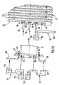
- Such an ignition coil is supplied with low voltage from an external connector 14 ( Figures 1 and 2) in which are overmolded bars 15, 16, 17, the ends of which 18, 19, 20 must be connected respectively at the ends of the primary winding 5 and at the low-voltage end of the secondary winding 9.
- the ends 18, 19, 20 of the bars 15, 16, 17 external to the connector 14 comprise an L-shaped part, the horizontal branch of which is of smaller width, said width corresponding to the slots 38, 39, 40 of the housings 35, 36, 37 of the secondary spool 8.
- the means for holding the connector assembly 14, bars 15, 16, 17 are formed by cooperation of the ends 18, 19, 20 of said bars with the housings 35, 36, 37 of the secondary coil 8.
- the ends 18, 19, 20 are rigid enough to support the connector 14 and the depth of the housings 35, 36, 37 is large enough to reinforce their rigidity.
- the connector assembly 14, bars 15, 16, 17 being thus positioned on the magnetic assembly, it suffices to make the desired electrical connections.
- the primary coil 6 is equipped with primary inserts 71 and 71 '.
- the primary insert 71 ′ being symmetrical and of identical design to the insert 71, has not been described in detail.
- the inserts 71, 71 ' are forced into the L-shaped slots 65 and 66 of the primary winding 6.
- the ends 69, 70 of the primary winding 5 are bent at right angles and are positioned in the clamps 73, 73 respectively.
- 'primary inserts 71, 71' where they are crimped.
- the secondary insert 51 is forced into the slot 41 of the secondary winding 8.
- the secondary winding 9 being produced, the low-voltage end of said winding 9 is fixed by winding and welding, to the inclined branch 56 of the secondary insert 51.
- the primary P and secondary S assemblies thus formed are assembled, then the low-voltage connector 14 fitted with its bars 15, 16, 17 is positioned by introducing the ends 18, 19, 20 into the housings 38, 39, 40 secondary coil 8.
- the arrangement of the assembly is such that the ends 18, 19, 20 of the bars 15, 16, 17 are received respectively in the clamps 75, 75 'and 59 where they are crimped.
Landscapes
- Engineering & Computer Science (AREA)
- Power Engineering (AREA)
- Ignition Installations For Internal Combustion Engines (AREA)
Claims (8)
- Zündspule, insbesondere für einen Kraftfahrzeug-Verbrennungsmotor, die, eingebaut in ein Gehäuse (1), einen magnetischen Komplex, der insbesondere aus einem Magnetkern (7) besteht, der in einem primären Wickelkörper (6) angeordnet ist, einen zweiten Wickelkörper (8), der mit dem ersten Wickelkörper (6) koaxial ist, Primärwicklungen (5) und Sekundärwicklungen (9), eine Magnetflußrückleitung (4), Mittel zur Niederspannungsversorgung, die insbesondere einen Steckverbinder (14) umfassen, in dem Stege (15, 16, 17) eingegossen sind, wobei diese Stege (15, 16, 17) außerhalb vom Steckverbinder (14) befindliche Enden (18, 19 20) aufweisen, sowie Mittel zum Festhalten des Steckverbinders (14) und der Stege (15, 16, 17) auf dem magnetischen Komplex aufweist, dadurch gekennzeichnet, daß die Mittel zum Festhalten von den Enden (18, 19, 20) der Stege (15, 16, 17) gebildet werden, die mit Aussparungen (38, 39, 40) zusammenwirken, welche in einem Flansch (32) des zweiten Wickelkörpers (8) vorgesehen sind.
- Zündspule nach Anspruch 1, dadurch gekennzeichnet, daß die Enden (18, 19, 20) der Stege (15, 16, 17) jeweils in Klemmen (75, 75', 59) eingeführt sind, die jeweils an ersten Einsätzen (71, 71') und an einem zweiten Einsatz (51) ausgebildet sind.
- Zündkerze nach Anspruch 2,dadurch gekennzeichnet, daß die Enden (18, 19, 20) der Stege (15, 16, 17) in den Klemmen (75, 75', 59) gequetscht werden.
- Zündspule nach Anspruch 3, dadurch gekennzeichnet, daß die ersten Einsätze (71, 71') an dem ersten Wickelkörper (6) befestigt werden, indem diese ersten Einsätze (71, 71') mit Kraft in auf einem Flansch (61) dieses ersten Wickelkörpers (6) vorgesehene L-förmige Schlitze (65, 66) hineingepreßt werden.
- Zündspule nach Anspruch 4, dadurch gekennzeichnet, daß die Enden (69, 70) der Primärwicklung (5) in Klemmen (73, 73') eingeführt sind, die an ersten Einsätzen (71, 71') ausgebildet sind.
- Zündspule nach Anspruch 5, dadurch gekennzeichnet, daß die Enden (69, 70) der Primärwicklung (5) in den Klemmen (73, 73') gequetscht werden.
- Zündspule nach Anspruch 2, dadurch gekennzeichnet, daß der zweite Einsatz (51) mittels einer aus dem Material vorgestanzten Lasche (57), die mit der Wand eines Schlitzes (41) eines Flansches (32) des sekundären Wickelkörpers (8) zusammenwirkt, in dem sekundären Wickelkörper (8) befestigt ist.
- Zündspule nach Anspruch 7, dadurch gekennzeichnet, daß das Niederspannungsende der Sekundärwicklung (9) durch Wickeln und/oder Schweißen auf einem an dem zweiten Einsatz (51) ausgebildeten schrägen Abschnitt (56) befestigt ist.
Applications Claiming Priority (2)
| Application Number | Priority Date | Filing Date | Title |
|---|---|---|---|
| FR8916102A FR2655474B1 (fr) | 1989-12-06 | 1989-12-06 | Connectique basse-tension d'une bobine d'allumage, en particulier pour moteur a combustion interne de vehicule automobile. |
| FR8916102 | 1989-12-06 |
Publications (2)
| Publication Number | Publication Date |
|---|---|
| EP0432026A1 EP0432026A1 (de) | 1991-06-12 |
| EP0432026B1 true EP0432026B1 (de) | 1994-04-06 |
Family
ID=9388199
Family Applications (1)
| Application Number | Title | Priority Date | Filing Date |
|---|---|---|---|
| EP90403425A Expired - Lifetime EP0432026B1 (de) | 1989-12-06 | 1990-12-03 | Niederspannungsverbinder für eine Zündspule, insbesondere für Brennkraftmaschine eines Kraftfahrzeuges |
Country Status (6)
| Country | Link |
|---|---|
| US (1) | US5053737A (de) |
| EP (1) | EP0432026B1 (de) |
| JP (1) | JPH04708A (de) |
| DE (1) | DE69007949T2 (de) |
| ES (1) | ES2055378T3 (de) |
| FR (1) | FR2655474B1 (de) |
Citations (1)
| Publication number | Priority date | Publication date | Assignee | Title |
|---|---|---|---|---|
| EP0395513A1 (de) * | 1989-04-28 | 1990-10-31 | Valeo Electronique | Niederspannungsverbinder für eine Zündspule, insbesondere für Brennkraftmaschine eines Kraftfahrzeuges |
Family Cites Families (8)
| Publication number | Priority date | Publication date | Assignee | Title |
|---|---|---|---|---|
| US3189857A (en) * | 1962-12-31 | 1965-06-15 | Gen Electric | Transformer bobbin |
| US3979707A (en) * | 1975-02-07 | 1976-09-07 | Ault Incorporated | Power-pack assembly |
| US4519015A (en) * | 1983-08-23 | 1985-05-21 | Lin Jiing S | Plug-in type of power supply |
| JPS6294612U (de) * | 1985-12-03 | 1987-06-17 | ||
| FR2602098B1 (fr) * | 1986-07-23 | 1988-09-16 | Ducellier & Cie | Connexions electriques du circuit secondaire d'une bobine d'allumage |
| JPS63142622A (ja) * | 1986-12-04 | 1988-06-15 | Nippon Denso Co Ltd | 内燃機関の点火コイル |
| US4766406A (en) * | 1987-04-16 | 1988-08-23 | Universal Manufacturing Corporation | Fluorescent ballast assembly |
| DE3730606A1 (de) * | 1987-09-11 | 1989-03-30 | Siemens Ag | Spulenkoerper |
-
1989
- 1989-12-06 FR FR8916102A patent/FR2655474B1/fr not_active Expired - Fee Related
-
1990
- 1990-11-30 US US07/619,982 patent/US5053737A/en not_active Expired - Fee Related
- 1990-12-03 EP EP90403425A patent/EP0432026B1/de not_active Expired - Lifetime
- 1990-12-03 ES ES90403425T patent/ES2055378T3/es not_active Expired - Lifetime
- 1990-12-03 DE DE69007949T patent/DE69007949T2/de not_active Expired - Fee Related
- 1990-12-06 JP JP2405339A patent/JPH04708A/ja active Pending
Patent Citations (1)
| Publication number | Priority date | Publication date | Assignee | Title |
|---|---|---|---|---|
| EP0395513A1 (de) * | 1989-04-28 | 1990-10-31 | Valeo Electronique | Niederspannungsverbinder für eine Zündspule, insbesondere für Brennkraftmaschine eines Kraftfahrzeuges |
Also Published As
| Publication number | Publication date |
|---|---|
| FR2655474B1 (fr) | 1992-04-24 |
| US5053737A (en) | 1991-10-01 |
| JPH04708A (ja) | 1992-01-06 |
| FR2655474A1 (fr) | 1991-06-07 |
| ES2055378T3 (es) | 1994-08-16 |
| DE69007949T2 (de) | 1994-11-17 |
| DE69007949D1 (de) | 1994-05-11 |
| EP0432026A1 (de) | 1991-06-12 |
Similar Documents
| Publication | Publication Date | Title |
|---|---|---|
| EP0511111B1 (de) | Elektrische Verbindung und Gehäuse für elektrische Bauteile mit einer solchen Verbindung | |
| EP0735629A1 (de) | Vorrichtung für die Verbindung von elektrischen Leitungsdrähten und Anschlussblock ausgerüstet mit obiger Vorrichtung | |
| FR2552595A1 (fr) | Dispositif pour la jonction des extremites de fils d'un enroulement de stator de moteurs electriques au moyen d'un connecteur d'enfichage | |
| EP0805605B1 (de) | Abzweigverbinder für Übertragungsnetze, insbesondere für die Telephonie und Datenverarbeitung | |
| EP0395512B1 (de) | Zündspule, insbesondere für Brennkraftmaschinen eines Kraftfahrzeuges und Mittel zur Sicherung des primären Zusammenbaus innerhalb des sekundären | |
| EP0432026B1 (de) | Niederspannungsverbinder für eine Zündspule, insbesondere für Brennkraftmaschine eines Kraftfahrzeuges | |
| EP0418136B1 (de) | Hochspannungsanschlussvorrichtung für eine Zündspule, insbesondere für Brennkraftmaschinen von Kraftfahrzeugen | |
| EP0211710B1 (de) | Anschlussklemme für Kabelleiter | |
| FR2646554A1 (fr) | Moyens de connexion des enroulements primaires d'une bobine d'allumage, en particulier pour moteur a combustion interne de vehicule automobile | |
| EP2662931A1 (de) | Anschlussschuh für isoliertes elektrisches Netzkabel, und Herstellungsverfahren dieses Anschlussschuhs | |
| FR2646553A1 (fr) | Connecteur basse-tension pour bobine d'allumage, en particulier pour moteur a combustion interne de vehicule automobile | |
| FR2655473A1 (fr) | Connectique haute-tension d'une bobine d'allumage, en particulier pour moteur a combustion interne de vehicule automobile. | |
| EP3349305B1 (de) | Verbessertes elektrisches anschlusskit | |
| EP1925011B1 (de) | Wärmekraftmaschinenanlasserschalter mit verbesserten elektrischen verbindungsmitteln der wicklung | |
| FR2657995A1 (fr) | Bobine d'allumage, notamment pour moteur a combustion interne de vehicule automobile. | |
| EP0418137B1 (de) | Zündspule, besonders für Brennkraftmaschinen von Kraftfahrzeugen | |
| FR2809529A1 (fr) | Ensemble de bobine electromagnetique pour un dispositif electromagnetique | |
| EP0132426A2 (de) | Zündspule für Verbrennungsmotor | |
| FR2823914A1 (fr) | Dispositif de blindage electromagnetique pour connecteur electrique | |
| FR2646551A1 (fr) | Connexions electriques du circuit secondaire d'une bobine d'allumage, en particulier pour moteur a combustion interne de vehicule automobile | |
| EP0172779A1 (de) | Mehrpoliger elektrischer Verbinder | |
| EP0780934B1 (de) | Kurzschliesseinrichtung für elektrischen Kontakte in Reihe | |
| FR2801347A1 (fr) | Dispositif d'allumage pour au moins deux bougies d'un moteur thermique a combustion interne | |
| EP2272135B1 (de) | Einrichtung zur verhinderung der erzeugung eines elektrischen bogens zwischen zwei leitfähigen elementen | |
| EP0557143A1 (de) | Gehäuse für ein Bündel elektrischer Leitungen verbindbar mit Anschlussklemmen |
Legal Events
| Date | Code | Title | Description |
|---|---|---|---|
| PUAI | Public reference made under article 153(3) epc to a published international application that has entered the european phase |
Free format text: ORIGINAL CODE: 0009012 |
|
| AK | Designated contracting states |
Kind code of ref document: A1 Designated state(s): DE ES GB IT |
|
| 17P | Request for examination filed |
Effective date: 19911212 |
|
| 17Q | First examination report despatched |
Effective date: 19921215 |
|
| RAP1 | Party data changed (applicant data changed or rights of an application transferred) |
Owner name: SAGEM ALLUMAGE |
|
| GRAA | (expected) grant |
Free format text: ORIGINAL CODE: 0009210 |
|
| AK | Designated contracting states |
Kind code of ref document: B1 Designated state(s): DE ES GB IT |
|
| REF | Corresponds to: |
Ref document number: 69007949 Country of ref document: DE Date of ref document: 19940511 |
|
| ITF | It: translation for a ep patent filed | ||
| GBT | Gb: translation of ep patent filed (gb section 77(6)(a)/1977) |
Effective date: 19940708 |
|
| REG | Reference to a national code |
Ref country code: ES Ref legal event code: FG2A Ref document number: 2055378 Country of ref document: ES Kind code of ref document: T3 |
|
| PLBE | No opposition filed within time limit |
Free format text: ORIGINAL CODE: 0009261 |
|
| STAA | Information on the status of an ep patent application or granted ep patent |
Free format text: STATUS: NO OPPOSITION FILED WITHIN TIME LIMIT |
|
| 26N | No opposition filed | ||
| PGFP | Annual fee paid to national office [announced via postgrant information from national office to epo] |
Ref country code: GB Payment date: 20011127 Year of fee payment: 12 |
|
| PGFP | Annual fee paid to national office [announced via postgrant information from national office to epo] |
Ref country code: ES Payment date: 20011210 Year of fee payment: 12 |
|
| PGFP | Annual fee paid to national office [announced via postgrant information from national office to epo] |
Ref country code: DE Payment date: 20011212 Year of fee payment: 12 |
|
| REG | Reference to a national code |
Ref country code: GB Ref legal event code: IF02 |
|
| PG25 | Lapsed in a contracting state [announced via postgrant information from national office to epo] |
Ref country code: GB Free format text: LAPSE BECAUSE OF NON-PAYMENT OF DUE FEES Effective date: 20021203 |
|
| PG25 | Lapsed in a contracting state [announced via postgrant information from national office to epo] |
Ref country code: ES Free format text: LAPSE BECAUSE OF NON-PAYMENT OF DUE FEES Effective date: 20021204 |
|
| PG25 | Lapsed in a contracting state [announced via postgrant information from national office to epo] |
Ref country code: DE Free format text: LAPSE BECAUSE OF NON-PAYMENT OF DUE FEES Effective date: 20030701 |
|
| GBPC | Gb: european patent ceased through non-payment of renewal fee | ||
| REG | Reference to a national code |
Ref country code: ES Ref legal event code: FD2A Effective date: 20021204 |
|
| PG25 | Lapsed in a contracting state [announced via postgrant information from national office to epo] |
Ref country code: IT Free format text: LAPSE BECAUSE OF NON-PAYMENT OF DUE FEES;WARNING: LAPSES OF ITALIAN PATENTS WITH EFFECTIVE DATE BEFORE 2007 MAY HAVE OCCURRED AT ANY TIME BEFORE 2007. THE CORRECT EFFECTIVE DATE MAY BE DIFFERENT FROM THE ONE RECORDED. Effective date: 20051203 |