EP0431985B1 - Vorrichtung zum Abführen und zur Reinigung von Auspuffgasen eines Motors - Google Patents
Vorrichtung zum Abführen und zur Reinigung von Auspuffgasen eines Motors Download PDFInfo
- Publication number
- EP0431985B1 EP0431985B1 EP90402813A EP90402813A EP0431985B1 EP 0431985 B1 EP0431985 B1 EP 0431985B1 EP 90402813 A EP90402813 A EP 90402813A EP 90402813 A EP90402813 A EP 90402813A EP 0431985 B1 EP0431985 B1 EP 0431985B1
- Authority
- EP
- European Patent Office
- Prior art keywords
- engine
- exhaust
- pipe
- flap
- opening
- Prior art date
- Legal status (The legal status is an assumption and is not a legal conclusion. Google has not performed a legal analysis and makes no representation as to the accuracy of the status listed.)
- Expired - Lifetime
Links
Images


Classifications
-
- F—MECHANICAL ENGINEERING; LIGHTING; HEATING; WEAPONS; BLASTING
- F01—MACHINES OR ENGINES IN GENERAL; ENGINE PLANTS IN GENERAL; STEAM ENGINES
- F01N—GAS-FLOW SILENCERS OR EXHAUST APPARATUS FOR MACHINES OR ENGINES IN GENERAL; GAS-FLOW SILENCERS OR EXHAUST APPARATUS FOR INTERNAL COMBUSTION ENGINES
- F01N13/00—Exhaust or silencing apparatus characterised by constructional features ; Exhaust or silencing apparatus, or parts thereof, having pertinent characteristics not provided for in, or of interest apart from, groups F01N1/00 - F01N5/00, F01N9/00, F01N11/00
- F01N13/08—Other arrangements or adaptations of exhaust conduits
-
- F—MECHANICAL ENGINEERING; LIGHTING; HEATING; WEAPONS; BLASTING
- F01—MACHINES OR ENGINES IN GENERAL; ENGINE PLANTS IN GENERAL; STEAM ENGINES
- F01N—GAS-FLOW SILENCERS OR EXHAUST APPARATUS FOR MACHINES OR ENGINES IN GENERAL; GAS-FLOW SILENCERS OR EXHAUST APPARATUS FOR INTERNAL COMBUSTION ENGINES
- F01N3/00—Exhaust or silencing apparatus having means for purifying, rendering innocuous, or otherwise treating exhaust
- F01N3/08—Exhaust or silencing apparatus having means for purifying, rendering innocuous, or otherwise treating exhaust for rendering innocuous
- F01N3/10—Exhaust or silencing apparatus having means for purifying, rendering innocuous, or otherwise treating exhaust for rendering innocuous by thermal or catalytic conversion of noxious components of exhaust
- F01N3/18—Exhaust or silencing apparatus having means for purifying, rendering innocuous, or otherwise treating exhaust for rendering innocuous by thermal or catalytic conversion of noxious components of exhaust characterised by methods of operation; Control
- F01N3/20—Exhaust or silencing apparatus having means for purifying, rendering innocuous, or otherwise treating exhaust for rendering innocuous by thermal or catalytic conversion of noxious components of exhaust characterised by methods of operation; Control specially adapted for catalytic conversion ; Methods of operation or control of catalytic converters
- F01N3/2006—Periodically heating or cooling catalytic reactors, e.g. at cold starting or overheating
-
- F—MECHANICAL ENGINEERING; LIGHTING; HEATING; WEAPONS; BLASTING
- F01—MACHINES OR ENGINES IN GENERAL; ENGINE PLANTS IN GENERAL; STEAM ENGINES
- F01N—GAS-FLOW SILENCERS OR EXHAUST APPARATUS FOR MACHINES OR ENGINES IN GENERAL; GAS-FLOW SILENCERS OR EXHAUST APPARATUS FOR INTERNAL COMBUSTION ENGINES
- F01N3/00—Exhaust or silencing apparatus having means for purifying, rendering innocuous, or otherwise treating exhaust
- F01N3/08—Exhaust or silencing apparatus having means for purifying, rendering innocuous, or otherwise treating exhaust for rendering innocuous
- F01N3/10—Exhaust or silencing apparatus having means for purifying, rendering innocuous, or otherwise treating exhaust for rendering innocuous by thermal or catalytic conversion of noxious components of exhaust
- F01N3/18—Exhaust or silencing apparatus having means for purifying, rendering innocuous, or otherwise treating exhaust for rendering innocuous by thermal or catalytic conversion of noxious components of exhaust characterised by methods of operation; Control
- F01N3/20—Exhaust or silencing apparatus having means for purifying, rendering innocuous, or otherwise treating exhaust for rendering innocuous by thermal or catalytic conversion of noxious components of exhaust characterised by methods of operation; Control specially adapted for catalytic conversion ; Methods of operation or control of catalytic converters
- F01N3/2053—By-passing catalytic reactors, e.g. to prevent overheating
-
- Y—GENERAL TAGGING OF NEW TECHNOLOGICAL DEVELOPMENTS; GENERAL TAGGING OF CROSS-SECTIONAL TECHNOLOGIES SPANNING OVER SEVERAL SECTIONS OF THE IPC; TECHNICAL SUBJECTS COVERED BY FORMER USPC CROSS-REFERENCE ART COLLECTIONS [XRACs] AND DIGESTS
- Y02—TECHNOLOGIES OR APPLICATIONS FOR MITIGATION OR ADAPTATION AGAINST CLIMATE CHANGE
- Y02T—CLIMATE CHANGE MITIGATION TECHNOLOGIES RELATED TO TRANSPORTATION
- Y02T10/00—Road transport of goods or passengers
- Y02T10/10—Internal combustion engine [ICE] based vehicles
- Y02T10/12—Improving ICE efficiencies
Definitions
- the invention relates to a device for evacuation and anti-pollution treatment of exhaust gases from an engine.
- the main pollutants that are controlled are gases such as carbon monoxide, hydrocarbons and nitrogen oxides.
- the catalytic converters currently used which are interposed on the exhaust line between the exhaust pipes of the engine and the expansion pot consist of a metal casing containing a mass of catalyst material having a very large contact surface for the gases exhaust passing through the catalytic converter.
- the polluting gases such as the gases mentioned above are eliminated by a chemical reaction of oxidation or reduction, in contact with the catalyst, as soon as the latter has been brought by the exhaust gases to a temperature sufficient to ensure the start of the chemical reaction.
- This minimum catalyst temperature is generally between 250 and 300 ° C depending on the age of the catalyst.
- the correct functioning of the catalytic converter also requires a good adjustment of the air-fuel mixture.
- the temperature of the catalyst must remain below a limit temperature above which the catalyst begins to deteriorate, in contact with the exhaust gases.
- the mass of catalytic material is generally constituted by a ceramic or metallic support comprising thousands of small channels crossed by the exhaust gases and covered with a layer of alumina which multiplies by approximately 7000 the active surface of the catalyst, c that is to say the surface of the catalyst coming into contact with the gases.
- alumina layer On the alumina layer, 2 to 3 g of precious metals are deposited, generally platinum and rodhium, which make it possible to accelerate the speeds of chemical reactions for the elimination of polluting gases.
- the exhaust line can be designed in different ways.
- a design known as "four in two" is used in which two of the exhaust pipes associated with two engine cylinders are connected to a first exhaust pipe and the other two pipes associated with the other two cylinders of the engine, with a second exhaust pipe.
- the two exhaust pipes are interconnected upstream of the expansion pot, and for example at the level of a catalytic converter.
- Siamese tube which is separated in its middle by a plane partition arranged along a diametrical plane.
- the Siamese tube is equivalent to two tubes of an exhaust line, each of the conduits separated by the flat partition being connected to two exhaust pipes associated with two engine cylinders.
- Exhaust systems with a Siamese tube are easier to accommodate under the vehicle floor and cause more heat loss weaker than two separate conduits, insofar as the two conduits of the Siamese tube have a common wall and a surface for exchange with the outside of a lower value for an equivalent cross-section of the conduits.
- a valve or valve device placed at the inlet or outlet of one of the catalytic converters makes it possible to interrupt the circulation of the exhaust gases in one of the two parallel conduits and to pass all the gases engine exhaust in the other conduit on which the second catalytic converter is placed, the two parallel conduits being interconnected upstream of the two catalytic converters.
- Such a device is however relatively more complex and more expensive than a device with a single catalytic converter.
- the exhaust duct has a branch at which it separates into a first duct passing through the mass of the catalyst and into a second duct opening into the envelope of the catalyst and a valve for opening or closing the ducts.
- Such a device which does not have two separate exhaust pipes, each connected at one of their ends to two engine exhaust pipes and, at their other end, to the catalytic converter, could not be used on engines high performance.
- valve for opening and closing the ducts is controlled as a function of the engine temperature only, so that the power level requested from the engine is not taken into account.
- exhaust gases only heat the mass of the catalyst, in the start-up phase, through the wall of the first duct.
- the devices according to the prior art do not allow optimal conditions to be obtained, both with regard to the cost of construction of the exhaust device and the operating conditions of this device, when the engine is cold started and during its hot operation.
- the object of the invention is therefore to propose a device for evacuation and anti-pollution treatment of exhaust gases from an engine comprising at least two parallel conduits each connected at one of its ends to a part of the pipes of exhaust fixed at the outlet of the engine cylinders and at its other end to at least one catalytic converter constituted by an envelope containing a mass of catalyst material allowing elimination of the harmful gases contained in the engine exhaust gases coming into contact with the catalyst , this device being relatively simple and inexpensive and making it possible to ensure good efficiency of the catalytic converter whatever the operating conditions of the engine.
- Figure 1 is a general exploded perspective view of an exhaust line having the characteristics according to the invention.
- Figure 2 is an enlarged view of part of the exhaust line shown in Figure 1 having an exhaust pipe of the Siamese tube type connected to a catalytic converter.
- FIG. 3 is a view in axial section on a larger scale of a part of the dual-duct exhaust pipe shown in FIG. 2 in which a closure flap of one of the ducts is placed.
- FIG. 3A is a view along A-A of FIG. 3.
- FIG. 3B is a view along B-B of FIG. 3.
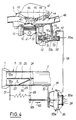
- Figure 4 is a partial sectional view in elevation showing the position of the shutter control means shown in Figures 3, 3A and 3B, when the engine is cold.
- Figure 5 is a partial sectional view in elevation showing the position of the closure flap control means shown in Figures 3, 3A and 3B, when the engine is hot.
- FIG. 6A is a functional diagram showing the circulation of gases in a Siamese tube of a device according to the invention, during the cold start of the engine.
- FIG. 6B is a functional diagram showing the circulation of the exhaust gases in a Siamese tube of a device according to the invention, during the hot operation of the engine or during a cold acceleration phase.
- Figure 6C is a cross-sectional view along C-C of Figure 6A.
- Figure 7 is a side elevational view of an exhaust device according to the invention and according to an alternative embodiment.
- FIG. 7A is a sectional view along A-A of FIG. 7.
- FIG. 8 is a top view of the exhaust device shown in FIG. 7.
- the expansion pot 5 is connected to an exhaust 6 whose outlet is constituted by a terminal exhaust pipe 7 opening to the atmosphere.
- the first exhaust pipe 2 is produced in the form of a Siamese tube with two conduits and, according to the invention, an opening and closing flap of one of the conduits of the Siamese tube 2 is placed in a portion 8 of the end of the tube 2 and connected to an opening and closing control assembly 10.
- FIG 2 there is shown the exhaust manifold 9 of a four-cylinder petrol engine comprising four pipes 11, 12, 13 and 14 respectively connected at their inlet end to the exhaust duct of the first, of the second, third and fourth cylinder and joined together at the outlet part of the manifold which has a partition 17, so that the pipes 11 and 14 of the first and fourth cylinders open into a first chamber 16a delimited by the partition 17 and the pipes 12 and 13 connected to the second and third cylinders in a second chamber 16b delimited by the partition 17.
- the outlet part of the exhaust manifold 9 comprises a connection flange 15 intended to ensure the fixing of the exhaust line by means of the connection piece 1 called a ball joint.
- the ball joint 1 is made integral with the end of the Siamese tube 2 by means of the portion 8 of this tube in which the closure flap of one of the conduits of the Siamese tube 2 is mounted.
- the Siamese tube 2 is constituted by a tubular metallic element whose internal volume is separated into two parts 18a and 18b of semi-circular section by a transverse partition 19 arranged diametrically in the tube 2.
- the partition 19 extends up to level of the entry part of the ball joint 1, so that when the siamese tube 2 is connected to the exhaust manifold 9, via the ball joint 1 and the flange 15, the chamber 16a of the manifold is in communication with the conduit 18a of the Siamese tube and the chamber 16b with the conduit 18b, as shown by the arrows 21 in dotted lines in FIG. 2.
- the end of the Siamese tube 2 opposite its connection portion to the ball joint 1 is connected to the casing of the catalytic converter 3, so that the conduits 18a and 18b of the tube 2 both open into the volume internal of the catalytic converter 3 occupied by a mass of catalyst with a large contact surface, as described above.
- the partition 19 has a through opening 20 inside the end 8 of the envelope of the tube 2, the semi-circular shape of which is visible in FIG. 3B.
- a closing flap 23 of the conduit 18b is mounted articulated by means of a pin 24 in the wall of the end part 8 of the Siamese tube 2.
- the flap 23 of semi-circular shape has a diameter greater than the diameter of the opening 20 in order to ensure complete covering of the edge of the opening in its raised position shown diagrammatically by the end 25a of the arrow 25 which symbolizes the displacements by pivoting the closing flap 23, in FIG. 3.
- the end 25b of the arrow 25 corresponds to the movement of the flap 23 in the closed position, as shown in FIG. 3, the edge of the flap then coming into contact with the internal surface of the conduit 18b of the Siamese tube 2.
- the outer edge of the flap 23 may have the shape of an ellipse with low eccentricity.
- One end of the axis 23 rotatably engaged in the wall of the end 8 of the tube 2 is protected externally by a casing 26 and the other end of the axis is connected to a control lever 28.
- the end of the axis 24 connected to the lever 28 crosses the wall of the end 8 of the tube 2, at a bearing 27 ensuring the rotary mounting of the axis 24 and a sealed passage from the end of the axis through the end wall 8 of the tube 2.
- the flap 23 is rigidly fixed on the axis 24, for example by means of rivets 29.
- the flap 23 is in the open position of the conduit 18b, which corresponds to the closing of the opening 20 of the partition 19, the outer edge of the flap being in the position indicated by the end 25a of arrow 25.
- the flap 23 is in the closed position of the conduit 18b of the siamese tube 2 and therefore in the open position of the opening 20 of the partition 19.
- the lever 28 secured to the axis 24 of the flap 23 is connected, in the vicinity of its end opposite the axis 24, to a first end of a helical return spring 30, the second end of which is connected to a fixed support 31 integral with the end portion 8 of the tube 2.
- the spring 30 tends to return the lever 28 in a direction corresponding to the opening of the conduit 18b, that is to say to the closing of the opening 20 of the partition 19 (arrow 32 in Figure 5).
- the end of the lever 28 opposite the axis 24 is also connected to the rod 33 of a pneumatic cylinder 34, the internal chamber of which is sealed in two parts by a partition 35 comprising a rigid central part 35a and a part flexible device 35b allowing movement of the partition 35 inside the room.
- the cylinder 34 is fixed on a support 37 integral with the Siamese tube 2, in the vicinity of its end part 8 containing the flap 23.
- the rod 33 is fixed at its end opposite to the lever 28, to the rigid part 35a of the partition 35 on which is also fixed a return spring 39 compressed and exerting pressure on the partition 35 so as to move the rod 33 in the direction of arrow 32 and to keep the flap in the closed position of the opening 20 of the partition 19.
- the springs 30 and 39 thus act in the same direction, so as to keep the shutter in the closed position of the opening 20.
- FIG. 4 In the upper part of Figures 4 and 5, there is shown the upper part of the cylinder block 40 of a gasoline engine, at the level of a cylinder 41 in which a piston 42 moves.
- the upper part of the cylinder 41 is closed by the cylinder head 43 in which are machined, at the upper part of the cylinder 41, an air and fuel mixture intake duct 44 and an exhaust duct 45.
- the exhaust manifold 9 is fixed to the cylinder head so as to put the exhaust duct 45 in communication with the tubing of the cylinder 41.
- An intake valve 45 and an exhaust valve 46 are mounted in the cylinder head 43 so as to ensure the opening and closing of the intake 44 and exhaust 45 conduits, respectively.
- a fuel injector 47 opens at the inlet of the intake pipe 44, slightly downstream of the valve 45.
- a butterfly valve comprising a shutter 48 is disposed in the intake pipe upstream of the injector 47.
- the opening of the butterfly shutter 48 is controlled, in the usual way, by the vehicle accelerator.
- the cylinder block 40 includes a jacket 50 in which the engine cooling water circulates.
- thermovalve 51 is tightly fixed in a threaded bore passing through a part of the cylinder block 40, so that the end of the thermovalve 51 constituted by a thermosensitive element 52 is in the immediate vicinity of the water circulating in the lining 50 with which it very quickly becomes in thermal equilibrium.
- thermovalve 51 comprises a chamber 51a in which a valve shutter 53 moves, having one end connected to the heat-sensitive element 52.
- the thermovalve 51 comprises a first nozzle 55 and a second nozzle 57 opening one and the other into the interior volume of the body of the thermovalve 51, in which the shutter drawer 53 moves.
- the nozzle 57 is connected by a tube 56 to the intake duct 44, downstream of the butterfly valve 48.
- the second nozzle 57 is connected by a tube 58 to the chamber of the pneumatic cylinder 34, on the side opposite to the rod 33.
- thermovalve 51 is pierced with an opening 59 in the vicinity of its outer end allowing its interior volume to be brought into the atmosphere.
- the heat-sensitive element 52 places the shutter with drawer 53 in its position shown on Figure 4. This shutter has an enlarged end portion 53a which is then in position closing the opening 59 for venting the internal volume of the body of the thermovalve 51.
- the chamber of the pneumatic cylinder 34 is placed in communication via the tube 58, of the internal volume of the thermovalve 51 and of the tube 56 with the intake duct 44 downstream of the butterfly valve 48.
- the chamber of the cylinder 34 is subjected to the depression in the intake duct, which causes the wall 35 and the rod 33 to move, in the direction of the arrow 60.
- the spring 39 is compressed, the end of the lever 28 connected to the rod 33 moves in the direction of arrow 60 and the spring 30 expands.
- the flap 23 is placed in the closed position of the conduit 18b, that is to say in the open position of the orifice 20.
- the conduit 2 of the device shown in FIGS. 6A and 6B is produced in the form of a Siamese tube comprising two superimposed conduits 18a, 18b separated by a partition 19.
- the heat losses are reduced, insofar as only one duct is in operation, which correspondingly reduces the surfaces for exchange with the outside atmosphere.
- the transfer time is reduced and the gas flow is concentrated on a smaller section of the mass of catalyst 61 disposed inside the casing 3 of the catalytic converter.
- This circulation of gases in a single conduit of the Siamese tube makes it possible to considerably reduce the time required to warm up the catalyst, this catalyst passing for example from an ambient temperature of 20 ° C to its activation temperature of 300 ° C.
- the anti-pollution tests are carried out after immobilization of the vehicle for a period of 12 hours at an ambient temperature of 20 to 25 °. Pollutant gas emissions are analyzed and measured (in g / km) during the catalyst warm-up phase.
- thermosensitive element 52 of the thermovalve 51 moves the shutter drawer 53 which comprises an enlarged part 53b, so that this part 53b interrupts the communication between the part of the interior volume of the body of the thermovalve 51 in which the nozzle 55 opens and the part of the body in which the nozzle 57 opens.
- the exhaust gases are then capable of circulating inside the two conduits 18a and 18b of the tube 2 simultaneously, as shown in FIG. 6B and shown diagrammatically by the arrows 65.
- the gases from cylinders 1 and 4 are conveyed to the catalytic converter 3 where they come into contact with the mass of catalyst 61 via the conduit 18a.
- the gases from cylinders 2 and 3 are routed through line 18b.
- the engine can thus develop its maximum power.
- the Siamese tube 2 has heated up as a whole also by thermal conduction.
- the engine is no longer in its starting phase, the mixture is less enriched with fuel and the quantity of polluting gases emitted is reduced.
- the control device described and shown in FIG. 4 allows the engine to develop significant power, in the event that the driver of the vehicle deems it necessary and accelerates fully to obtain this power.
- the butterfly valve 48 opens fully and the vacuum in the intake manifold and in particular in the part of the intake duct 44 located downstream of the butterfly valve 48 decreases to a close value. of the value zero.
- the pneumatic cylinder 34 no longer ensures the retention of the rod 33 in the direction of the arrow 33 and the spring 30 ensures the return of the lever 28 in the direction of the arrow 32, as shown in Figure 5.
- the flap 23 comes apply in the closed position of the opening 20 and the device operates as in the case where the engine is hot, the gases flowing simultaneously in the conduits 18a and 18b, as shown in FIG. 6B.
- the engine can then develop the requested power.
- the mass of catalyst 61 is not yet at its activation temperature and that consequently, the polluting gases contained in the exhaust gases are not eliminated in significant quantity.
- the gas flow rate is important and the time required to warm up the catalyst is reduced and with it, the emissions of polluting gases.
- FIGS. 7, 7A and 8 a variant of an exhaust device according to the invention is shown, comprising a ball joint 62 for connecting to the exhaust manifold of an engine, two parallel pipes 63a and 63b connected to the 'one of their ends by a bypass line 64 and a catalytic converter 65 containing a mass of catalyst 66 into which open the end portions of the lines 63a and 63b opposite the bypass 64 and the ball joint 62.
- a shutter 67 for closing the conduit 63b is placed at the branch 64 so that in the open position of the conduit 63b, the shutter 67 closes the branch 64.
- the shutter 67 is controlled by a device as shown in the Figures 4 and 5.
- FIGS. 7, 7A and 8 are identical to the operation and the advantages described above in the case of an exhaust device with a Siamese tube.
- the temperature setting up of the conduit 63b in which the exhaust gases are not put into circulation takes place more slowly and less easily than in the case of a tube device Siamese.
- the heat losses are higher, insofar as the external contact and exchange surface of the conduits, with identical passage sections, is greater than in the case of a Siamese tube with two conduits.
- the device makes it possible to effectively remove polluting gases during the engine start-up phase and to ensure operation at full power both when the engine is cold and when the engine is hot.
- the device is compact and uses simple control means and whose operation is very safe.
- the housing in which is mounted the closing and opening flap of one of the exhaust pipe conduits can be constituted not only by an initial part of the exhaust pipe but also by a suitable housing on the engine exhaust manifold to which the end of the exhaust pipe is connected.
- the opening and closing flap of one of the exhaust pipe conduits can be controlled not only in the manner which has been described but also by a temperature probe placed in the mass of the catalyst and connected to a circuit of control of the opening and closing of the shutter.
- Putting the shutter in the open position in order to allow the passage of gases in the two exhaust pipe conduits can be ensured by a device ensuring a time delay and allowing opening after a certain time interval following start-up. of the motor.
- the invention can use catalytic converters of different type, that these pots contain a catalyst allowing oxidation or reduction of the polluting gases contained in the exhaust gases or even that they are produced in the form of 'a three-way structure.
- the invention applies to any device for removing and treating the exhaust gases of an engine, whether this engine is used on a road vehicle, on any other type of vehicle or on a fixed installation.
Claims (10)
- Vorrichtung zum Abführen und zur Reinigung von Auspuffgasen eines Motors, mit wenigstens zwei parallelen Leitungen (18a,18b;63a,63b), die jede an einem ihrer Enden an einen Teil der am Auslaß der Zylinder des Motors befestigten Auspuffstutzen (11,12,13,14) und an ihrem anderen Ende an wenigstens einen Katalysator (3,65) angeschlossen sind, der durch eine Hülle gebildet wird, die eine Masse aus Katalysatormaterial (61,66) aufnimmt, die eine Beseitigung von Schadstoffgasen gestattet, die in den Auspuffgasen des Motors enthalten sind, die mit dem Katalysator (61,66) in Berührung kommen, dadurchgekennzeichnet, daß:- die beiden parallelen Leitungen (18a,18b;63a,63b) an eine einzige Hülle (3,65) angeschlossen sind, die die Masse des Katalysatormaterials (61,66) enthält, und derart in zwei benachbarten Zonen in die Hülle münden, daß zwei parallele Auspuffgasströme in zwei benachbarte Bereiche der Masse des Katalysatormaterials geleitet werden,- und daß eine der Leitungen, oder erste Leitung, (18b; 63b) eine Verschlußklappe (23;67) aufweist, die mit Steuermitteln (51,34) verbunden ist, die das Schließen oder Öffnen der ersten Leitung während der Kaltstartphase des Motors in Abhängigkeit von der geforderten Motorleistung gestatten und die Klappe (23,67) in der Offenstellung halten, wenn der Motor heiß ist, wobei in der Schließstellung der ersten Leitung zwischen den beiden Leitungen eine Verbindung zum Abführen der Gase aus der ersten Leitung besteht.
- Vorrichtung nach Anspruch 1, dadurch gekennzeichnet, daß die beiden parallelen Leitungen (18a,18b) im Inneren einer rohrförmigen zylindrischen Leitung (2) durch eine axial gerichtete diametrale Wand (19) begrenzt werden.
- Vorrichtung nach Anspruch 2, dadurch gekennzeichnet, daß die Wand (19) eine Öffnung (20) in einer dem Anschlußende der rohrförmigen Leitung (2) an die Stutzen (9) des Motors benachbarten Zone aufweist, wobei die Klappe (23) in der Weise gelenkig an einem geradlinigen Rand der Öffnung (20) montiert ist, daß sie durch Schwenken verstellbar ist zwischen einer Schließstellung für eine der parallelen Leitungen (18b), in der sie sich an die Wand der Leitung (18b) anlegt, und einer Offenstellung, in der sie sich an die Wand (19) im Bereich der Öffnung (20) anlegt, so daß sie diese bedeckt, um sie zu schließen.
- Vorrichtung nach Anspruch 3, dadurch gekennzeichnet, daß die Klappe (23) mit einem Hebel (28) verbunden ist, der außerhalb des Rohres (2) angeordnet ist, so daß er durch die Steuermittel (51,34) betätigbar ist.
- Vorrichtung nach einem der Ansprüche 1 bis 4, dadurch gekennzeichnet, daß die Steuermittel gebildet werden durch ein am Motorblock (40) eines Zylinders (41) des Motors befestigtes Thermoventil (51) mit einem thermoempfindlichen Element in thermischem Kontakt mit dem im Mantel des Zylinderblocks (40) des Motors zirkulierenden Kühlwasser, einer Kammer, die durch eine Öffnung (59) mit der Atmosphäre kommuniziert, durch eine Leitung (55,56) mit der Ansaugleitung (44) des Zylinders (41) stromabwärts der Drosselklappe (48) kommuniziert und mit der Kammer eines Pneumatikzylinders (34) über eine Leitung (58) kommuniziert, sowie mit einem Schiebekolben (53), der mit dem thermoempfindlichen Element (52) verbunden ist und zwei vergrößerte Abschnitte (53a,53b) aufweist, die in der Lage sind, entweder die Öffnung (59) zur Verbindung der Kammer des Thermoventils (51) mit der Atmosphäre zu schließen und die Ansaugleitung (44) des Zylinders mit der Kammer des Pneumatikzylinders (34) zu verbinden oder die Kammer des Thermoventils (51) der Atmosphäre auszusetzen und gleichzeitig die Verbindung zwischen der Ansaugleitung (44) des Zylinders und der Kammer des Pneumatikzylinders (34) zu unterbrechen, wobei das Pneumatikventil (34) eine Kolbenstange (33) aufweist, die an einer zumindest teilweise verformbaren Wand (35) zum Verschließen der Kammer des Pneumatikzylinders (34) angebracht und an ihrem der Wand (35) des Zylinders (34) entgegengesetzten Ende mit einem Organ (28) zum Öffnen und Schließen der Schließklappe (23) für eine der Auspuffleitungen (18b) verbunden ist.
- Vorrichtung nach Anspruch 5, dadurch gekennzeichnet, daß das Organ (28) zum Öffnen und Schließen der Klappe (23) durch einen Hebel gebildet wird, der an einer Schwenkachse (24) für die Klappe (23) angebracht und mit einem Ende einer elastischen Rückstelleinrichtung (30) verbunden ist, deren anderes Ende mit einem Halter (31) verbunden ist, der an wenigstens einer der Auspuffleitungen (18a,18b) befestigt ist.
- Vorrichtung nach Anspruch 5 oder 6, dadurch gekennzeichnet, daß die Wand (35) der Kammer des Pneumatikzylinders (34) mit einer schraubenförmigen Rückstellfeder (39) verbunden ist, deren anderes Ende so mit dem Gehäuse des Zylinders (34) verbunden ist, daß die Kolbenstange (33) des Zylinders (34) und das Betätigungsorgan (28) für die Klappe (23) in die Offenstellung der Auspuffleitung (18b) zurückgestellt werden.
- Vorrichtung nach einem der Ansprüche 1 bis 7, dadurch gekennzeichnet, daß die Schließklappe (23) für die Auspuffleitung (18b) im Inneren eines Gehäuses (8) montiert ist, das am Ende der Auspuffleitung sitzt und mit den Stutzen (11,12,13,14) des Motors verbunden ist.
- Vorrichtung nach einem der Ansprüche 1 bis 7, dadurch gekennzeichnet, daß die Schließklappe (23) im Inneren eines Gehäuses (8) montiert ist, das an einem Auspuffkrümmer (9) ausgebildet ist, der die Stutzen (11,12,13,14) des Motors mit seinem für den Anschluß an die Auspuffleitungen bestimmten Auslaßende verbindet.
- Vorrichtung nach Anspruch 1, dadurch gekennzeichnet, daß die parallel angeordneten Auspuffleitungen (63a,63b) zwei getrennte rohrförmige, zylindrische Leitungen sind, die in der Nähe ihres Anschlußendes an die Stutzen des Motors durch eine Zweigleitung (64) miteinander verbunden sind und an ihrem anderen Ende mit der Hülle (65) des Katalysators verbunden sind,
wobei die Schließklappe (67) für eine der Leitungen (63b) gelenkig in Höhe der Zweigleitung (64) montiert ist, so daß sie schwenkbar ist zwischen einer Stellung zum Verschließen der Leitung (63b) und einer Stellung zum Verschließen der Zweigleitung (64) und zum Öffnen der Leitung (63b).
Applications Claiming Priority (2)
| Application Number | Priority Date | Filing Date | Title |
|---|---|---|---|
| FR8916126 | 1989-12-06 | ||
| FR8916126A FR2655376B1 (fr) | 1989-12-06 | 1989-12-06 | Dispositif d'evacuation et de traitement anti-pollution de gaz d'echappement d'un moteur et procede correspondant. |
Publications (2)
| Publication Number | Publication Date |
|---|---|
| EP0431985A1 EP0431985A1 (de) | 1991-06-12 |
| EP0431985B1 true EP0431985B1 (de) | 1993-09-01 |
Family
ID=9388214
Family Applications (1)
| Application Number | Title | Priority Date | Filing Date |
|---|---|---|---|
| EP90402813A Expired - Lifetime EP0431985B1 (de) | 1989-12-06 | 1990-10-09 | Vorrichtung zum Abführen und zur Reinigung von Auspuffgasen eines Motors |
Country Status (3)
| Country | Link |
|---|---|
| EP (1) | EP0431985B1 (de) |
| DE (1) | DE69003080T2 (de) |
| FR (1) | FR2655376B1 (de) |
Cited By (1)
| Publication number | Priority date | Publication date | Assignee | Title |
|---|---|---|---|---|
| EP3803070B1 (de) * | 2018-05-31 | 2024-02-28 | BRP-Rotax GmbH & Co. KG | Abluftsystem für motor |
Families Citing this family (2)
| Publication number | Priority date | Publication date | Assignee | Title |
|---|---|---|---|---|
| FR2678023B1 (fr) * | 1991-06-18 | 1993-10-08 | Institut Francais Petrole | Ligne d'echappement permettant un amorcage plus rapide du catalyseur. |
| US10865700B2 (en) | 2017-07-10 | 2020-12-15 | Bombardier Recreational Products Inc. | Air intake and exhaust systems for a snowmobile engine |
Family Cites Families (12)
| Publication number | Priority date | Publication date | Assignee | Title |
|---|---|---|---|---|
| GB1255823A (en) * | 1968-09-14 | 1971-12-01 | Honda Motor Co Ltd | Improvements in or relating to internal combustion engines |
| DE2104711C3 (de) * | 1971-02-02 | 1974-03-14 | Adam Opel Ag, 6090 Ruesselsheim | Vorrichtung zur katalytischen Nachverbrennung der Abgase von Brennkraftmaschinen |
| US3744248A (en) * | 1972-04-10 | 1973-07-10 | Gen Motors Corp | Catalytic convertor temperature control system |
| DE2237781A1 (de) * | 1972-08-01 | 1974-02-14 | Volkswagenwerk Ag | Brennkraftmaschine, insbesondere fuer kraftfahrzeuge, mit einer einrichtung zur beseitigung schaedlicher abgasbestandteile |
| DE2303773A1 (de) * | 1973-01-26 | 1974-08-01 | Volkswagenwerk Ag | Anordnung zur abgasfuehrung |
| US3984975A (en) * | 1975-11-10 | 1976-10-12 | General Motors Corporation | Internal combustion engine exhaust emission control |
| JPS5851212A (ja) * | 1981-09-22 | 1983-03-25 | Nissan Motor Co Ltd | 気筒数制御エンジンの排気処理装置 |
| JPS58163639U (ja) * | 1982-04-27 | 1983-10-31 | 日産自動車株式会社 | タ−ボチヤ−ジヤ−付エンジンのタ−ビンバイパス装置 |
| DE8432079U1 (de) * | 1984-11-02 | 1986-04-17 | Audi AG, 8070 Ingolstadt | Abgasrohr |
| FR2608677B1 (fr) * | 1986-12-19 | 1989-04-28 | Inst Francais Du Petrole | Dispositif et procede d'amorcage rapide d'un catalyseur d'oxydation pour un moteur deux temps |
| DE3736844A1 (de) * | 1987-10-30 | 1989-05-11 | Bayerische Motoren Werke Ag | Verfahren zur beeinflussung der temperatur von abgasen und abgasanlage zur durchfuehrung des verfahrens |
| GB8817962D0 (en) * | 1988-07-28 | 1988-09-01 | Austin Rover Group | Exhaust manifold |
-
1989
- 1989-12-06 FR FR8916126A patent/FR2655376B1/fr not_active Expired - Fee Related
-
1990
- 1990-10-09 DE DE90402813T patent/DE69003080T2/de not_active Expired - Fee Related
- 1990-10-09 EP EP90402813A patent/EP0431985B1/de not_active Expired - Lifetime
Cited By (1)
| Publication number | Priority date | Publication date | Assignee | Title |
|---|---|---|---|---|
| EP3803070B1 (de) * | 2018-05-31 | 2024-02-28 | BRP-Rotax GmbH & Co. KG | Abluftsystem für motor |
Also Published As
| Publication number | Publication date |
|---|---|
| EP0431985A1 (de) | 1991-06-12 |
| DE69003080T2 (de) | 1993-12-16 |
| FR2655376A1 (fr) | 1991-06-07 |
| DE69003080D1 (de) | 1993-10-07 |
| FR2655376B1 (fr) | 1992-04-03 |
Similar Documents
| Publication | Publication Date | Title |
|---|---|---|
| EP0913561B1 (de) | Auspuff- und Abgasrückführungsleitung einer Brennkraftmaschine | |
| EP0519778B1 (de) | Motorauspufflinie zum schnellen Erregen eines Katalysators | |
| EP0908606B1 (de) | Abgasanlage für einen Kraftfahrzeugmotor | |
| FR2711183A1 (fr) | Système d'échappement des gaz pour un moteur à combustion interne avec un turbocompresseur des gaz d'échappement. | |
| FR2772829A1 (fr) | Pot catalytique a gestion de temperature, notamment pour un vehicule automobile | |
| FR2714696A1 (fr) | Procédé pour réduire des émissions d'hydrocarbures d'un moteur à combustion interne et dispositif pour la mise en Óoeuvre de ce procédé. | |
| FR2689933A1 (fr) | Tuyau d'échappement de moteur à combustion interne comportant un catalyseur de démarrage disposé à proximité du moteur . | |
| FR2744763A1 (fr) | Turbocompresseur entraine par les gaz d'echappement d'un moteur a combustion interne | |
| FR2483515A1 (fr) | Dispositif antipollution pour moteur a combustion interne a turbocompresseur | |
| EP0431985B1 (de) | Vorrichtung zum Abführen und zur Reinigung von Auspuffgasen eines Motors | |
| WO2005024193A1 (fr) | Dispositif de regulation thermique de gaz d’echappement | |
| WO2002052142A1 (fr) | Module echangeur de chaleur, specialement concu pour un systeme de recyclage des gaz d'echappement | |
| WO2007000541A2 (fr) | Dispositif de chauffage additionnel d'un vehicule automobile | |
| EP2163743B1 (de) | Verfahren zur Behandlung von Schadstoffe, die in den Abgasen eines Verbrennungsmotors enthalten sind | |
| FR2752880A1 (fr) | Dispositif de suralimentation pour moteur a combustion interne | |
| FR2841595A1 (fr) | Tube des gaz d'echappement pour l'installation des gaz d'echappement d'un vehicule automobile | |
| FR2859238A1 (fr) | Dispositif de regulation thermique de gaz d'echappement | |
| FR2731746A1 (fr) | Dispositif d'echappement pour moteur a combustion | |
| FR2729184A1 (fr) | Dispositif a soupape, notamment pour une soupape de reinjection de gaz d'echappement d'un moteur a combustion interne | |
| FR2919674A1 (fr) | Dispositif d'orientation et de regulation des gaz d'echappement d'un moteur thermique dans un circuit de recirculation de gaz d'echappement appele egr vers l'admission d'air | |
| FR3124220A1 (fr) | Ligne d’echappement equipee d’une chambre de stockage de gaz d’echappement | |
| FR2717858A1 (fr) | Dispositif d'échappement pour moteur à combustion interne. | |
| EP1118750A1 (de) | Vorrichtung zum Abführen und zur Reinigung von Abgasen eines Verbrennungsmotors | |
| EP4321782A1 (de) | Doppelfeder-ventil mit mechanischer klappe und vorwärmschaltung damit | |
| EP0371841B1 (de) | Kühlkreis einer Brennkraftmaschine eines Kraftwagens |
Legal Events
| Date | Code | Title | Description |
|---|---|---|---|
| PUAI | Public reference made under article 153(3) epc to a published international application that has entered the european phase |
Free format text: ORIGINAL CODE: 0009012 |
|
| 17P | Request for examination filed |
Effective date: 19910325 |
|
| AK | Designated contracting states |
Kind code of ref document: A1 Designated state(s): DE GB IT |
|
| 17Q | First examination report despatched |
Effective date: 19920624 |
|
| GRAA | (expected) grant |
Free format text: ORIGINAL CODE: 0009210 |
|
| AK | Designated contracting states |
Kind code of ref document: B1 Designated state(s): DE GB IT |
|
| ITF | It: translation for a ep patent filed |
Owner name: BUGNION S.P.A. |
|
| GBT | Gb: translation of ep patent filed (gb section 77(6)(a)/1977) |
Effective date: 19930902 |
|
| REF | Corresponds to: |
Ref document number: 69003080 Country of ref document: DE Date of ref document: 19931007 |
|
| PLBE | No opposition filed within time limit |
Free format text: ORIGINAL CODE: 0009261 |
|
| STAA | Information on the status of an ep patent application or granted ep patent |
Free format text: STATUS: NO OPPOSITION FILED WITHIN TIME LIMIT |
|
| 26N | No opposition filed | ||
| PGFP | Annual fee paid to national office [announced via postgrant information from national office to epo] |
Ref country code: DE Payment date: 19980921 Year of fee payment: 9 |
|
| PGFP | Annual fee paid to national office [announced via postgrant information from national office to epo] |
Ref country code: GB Payment date: 19981001 Year of fee payment: 9 |
|
| PG25 | Lapsed in a contracting state [announced via postgrant information from national office to epo] |
Ref country code: GB Free format text: LAPSE BECAUSE OF NON-PAYMENT OF DUE FEES Effective date: 19991009 |
|
| GBPC | Gb: european patent ceased through non-payment of renewal fee |
Effective date: 19991009 |
|
| PG25 | Lapsed in a contracting state [announced via postgrant information from national office to epo] |
Ref country code: DE Free format text: LAPSE BECAUSE OF NON-PAYMENT OF DUE FEES Effective date: 20000801 |
|
| PG25 | Lapsed in a contracting state [announced via postgrant information from national office to epo] |
Ref country code: IT Free format text: LAPSE BECAUSE OF NON-PAYMENT OF DUE FEES Effective date: 20051009 |