EP0431985B1 - Evacuation and anti-pollution treatment device of exhaust gases of an engine - Google Patents
Evacuation and anti-pollution treatment device of exhaust gases of an engine Download PDFInfo
- Publication number
- EP0431985B1 EP0431985B1 EP90402813A EP90402813A EP0431985B1 EP 0431985 B1 EP0431985 B1 EP 0431985B1 EP 90402813 A EP90402813 A EP 90402813A EP 90402813 A EP90402813 A EP 90402813A EP 0431985 B1 EP0431985 B1 EP 0431985B1
- Authority
- EP
- European Patent Office
- Prior art keywords
- engine
- exhaust
- pipe
- flap
- opening
- Prior art date
- Legal status (The legal status is an assumption and is not a legal conclusion. Google has not performed a legal analysis and makes no representation as to the accuracy of the status listed.)
- Expired - Lifetime
Links
Images


Classifications
-
- F—MECHANICAL ENGINEERING; LIGHTING; HEATING; WEAPONS; BLASTING
- F01—MACHINES OR ENGINES IN GENERAL; ENGINE PLANTS IN GENERAL; STEAM ENGINES
- F01N—GAS-FLOW SILENCERS OR EXHAUST APPARATUS FOR MACHINES OR ENGINES IN GENERAL; GAS-FLOW SILENCERS OR EXHAUST APPARATUS FOR INTERNAL COMBUSTION ENGINES
- F01N13/00—Exhaust or silencing apparatus characterised by constructional features ; Exhaust or silencing apparatus, or parts thereof, having pertinent characteristics not provided for in, or of interest apart from, groups F01N1/00 - F01N5/00, F01N9/00, F01N11/00
- F01N13/08—Other arrangements or adaptations of exhaust conduits
-
- F—MECHANICAL ENGINEERING; LIGHTING; HEATING; WEAPONS; BLASTING
- F01—MACHINES OR ENGINES IN GENERAL; ENGINE PLANTS IN GENERAL; STEAM ENGINES
- F01N—GAS-FLOW SILENCERS OR EXHAUST APPARATUS FOR MACHINES OR ENGINES IN GENERAL; GAS-FLOW SILENCERS OR EXHAUST APPARATUS FOR INTERNAL COMBUSTION ENGINES
- F01N3/00—Exhaust or silencing apparatus having means for purifying, rendering innocuous, or otherwise treating exhaust
- F01N3/08—Exhaust or silencing apparatus having means for purifying, rendering innocuous, or otherwise treating exhaust for rendering innocuous
- F01N3/10—Exhaust or silencing apparatus having means for purifying, rendering innocuous, or otherwise treating exhaust for rendering innocuous by thermal or catalytic conversion of noxious components of exhaust
- F01N3/18—Exhaust or silencing apparatus having means for purifying, rendering innocuous, or otherwise treating exhaust for rendering innocuous by thermal or catalytic conversion of noxious components of exhaust characterised by methods of operation; Control
- F01N3/20—Exhaust or silencing apparatus having means for purifying, rendering innocuous, or otherwise treating exhaust for rendering innocuous by thermal or catalytic conversion of noxious components of exhaust characterised by methods of operation; Control specially adapted for catalytic conversion ; Methods of operation or control of catalytic converters
- F01N3/2006—Periodically heating or cooling catalytic reactors, e.g. at cold starting or overheating
-
- F—MECHANICAL ENGINEERING; LIGHTING; HEATING; WEAPONS; BLASTING
- F01—MACHINES OR ENGINES IN GENERAL; ENGINE PLANTS IN GENERAL; STEAM ENGINES
- F01N—GAS-FLOW SILENCERS OR EXHAUST APPARATUS FOR MACHINES OR ENGINES IN GENERAL; GAS-FLOW SILENCERS OR EXHAUST APPARATUS FOR INTERNAL COMBUSTION ENGINES
- F01N3/00—Exhaust or silencing apparatus having means for purifying, rendering innocuous, or otherwise treating exhaust
- F01N3/08—Exhaust or silencing apparatus having means for purifying, rendering innocuous, or otherwise treating exhaust for rendering innocuous
- F01N3/10—Exhaust or silencing apparatus having means for purifying, rendering innocuous, or otherwise treating exhaust for rendering innocuous by thermal or catalytic conversion of noxious components of exhaust
- F01N3/18—Exhaust or silencing apparatus having means for purifying, rendering innocuous, or otherwise treating exhaust for rendering innocuous by thermal or catalytic conversion of noxious components of exhaust characterised by methods of operation; Control
- F01N3/20—Exhaust or silencing apparatus having means for purifying, rendering innocuous, or otherwise treating exhaust for rendering innocuous by thermal or catalytic conversion of noxious components of exhaust characterised by methods of operation; Control specially adapted for catalytic conversion ; Methods of operation or control of catalytic converters
- F01N3/2053—By-passing catalytic reactors, e.g. to prevent overheating
-
- Y—GENERAL TAGGING OF NEW TECHNOLOGICAL DEVELOPMENTS; GENERAL TAGGING OF CROSS-SECTIONAL TECHNOLOGIES SPANNING OVER SEVERAL SECTIONS OF THE IPC; TECHNICAL SUBJECTS COVERED BY FORMER USPC CROSS-REFERENCE ART COLLECTIONS [XRACs] AND DIGESTS
- Y02—TECHNOLOGIES OR APPLICATIONS FOR MITIGATION OR ADAPTATION AGAINST CLIMATE CHANGE
- Y02T—CLIMATE CHANGE MITIGATION TECHNOLOGIES RELATED TO TRANSPORTATION
- Y02T10/00—Road transport of goods or passengers
- Y02T10/10—Internal combustion engine [ICE] based vehicles
- Y02T10/12—Improving ICE efficiencies
Definitions
- the invention relates to a device for evacuation and anti-pollution treatment of exhaust gases from an engine.
- the main pollutants that are controlled are gases such as carbon monoxide, hydrocarbons and nitrogen oxides.
- the catalytic converters currently used which are interposed on the exhaust line between the exhaust pipes of the engine and the expansion pot consist of a metal casing containing a mass of catalyst material having a very large contact surface for the gases exhaust passing through the catalytic converter.
- the polluting gases such as the gases mentioned above are eliminated by a chemical reaction of oxidation or reduction, in contact with the catalyst, as soon as the latter has been brought by the exhaust gases to a temperature sufficient to ensure the start of the chemical reaction.
- This minimum catalyst temperature is generally between 250 and 300 ° C depending on the age of the catalyst.
- the correct functioning of the catalytic converter also requires a good adjustment of the air-fuel mixture.
- the temperature of the catalyst must remain below a limit temperature above which the catalyst begins to deteriorate, in contact with the exhaust gases.
- the mass of catalytic material is generally constituted by a ceramic or metallic support comprising thousands of small channels crossed by the exhaust gases and covered with a layer of alumina which multiplies by approximately 7000 the active surface of the catalyst, c that is to say the surface of the catalyst coming into contact with the gases.
- alumina layer On the alumina layer, 2 to 3 g of precious metals are deposited, generally platinum and rodhium, which make it possible to accelerate the speeds of chemical reactions for the elimination of polluting gases.
- the exhaust line can be designed in different ways.
- a design known as "four in two" is used in which two of the exhaust pipes associated with two engine cylinders are connected to a first exhaust pipe and the other two pipes associated with the other two cylinders of the engine, with a second exhaust pipe.
- the two exhaust pipes are interconnected upstream of the expansion pot, and for example at the level of a catalytic converter.
- Siamese tube which is separated in its middle by a plane partition arranged along a diametrical plane.
- the Siamese tube is equivalent to two tubes of an exhaust line, each of the conduits separated by the flat partition being connected to two exhaust pipes associated with two engine cylinders.
- Exhaust systems with a Siamese tube are easier to accommodate under the vehicle floor and cause more heat loss weaker than two separate conduits, insofar as the two conduits of the Siamese tube have a common wall and a surface for exchange with the outside of a lower value for an equivalent cross-section of the conduits.
- a valve or valve device placed at the inlet or outlet of one of the catalytic converters makes it possible to interrupt the circulation of the exhaust gases in one of the two parallel conduits and to pass all the gases engine exhaust in the other conduit on which the second catalytic converter is placed, the two parallel conduits being interconnected upstream of the two catalytic converters.
- Such a device is however relatively more complex and more expensive than a device with a single catalytic converter.
- the exhaust duct has a branch at which it separates into a first duct passing through the mass of the catalyst and into a second duct opening into the envelope of the catalyst and a valve for opening or closing the ducts.
- Such a device which does not have two separate exhaust pipes, each connected at one of their ends to two engine exhaust pipes and, at their other end, to the catalytic converter, could not be used on engines high performance.
- valve for opening and closing the ducts is controlled as a function of the engine temperature only, so that the power level requested from the engine is not taken into account.
- exhaust gases only heat the mass of the catalyst, in the start-up phase, through the wall of the first duct.
- the devices according to the prior art do not allow optimal conditions to be obtained, both with regard to the cost of construction of the exhaust device and the operating conditions of this device, when the engine is cold started and during its hot operation.
- the object of the invention is therefore to propose a device for evacuation and anti-pollution treatment of exhaust gases from an engine comprising at least two parallel conduits each connected at one of its ends to a part of the pipes of exhaust fixed at the outlet of the engine cylinders and at its other end to at least one catalytic converter constituted by an envelope containing a mass of catalyst material allowing elimination of the harmful gases contained in the engine exhaust gases coming into contact with the catalyst , this device being relatively simple and inexpensive and making it possible to ensure good efficiency of the catalytic converter whatever the operating conditions of the engine.
- Figure 1 is a general exploded perspective view of an exhaust line having the characteristics according to the invention.
- Figure 2 is an enlarged view of part of the exhaust line shown in Figure 1 having an exhaust pipe of the Siamese tube type connected to a catalytic converter.
- FIG. 3 is a view in axial section on a larger scale of a part of the dual-duct exhaust pipe shown in FIG. 2 in which a closure flap of one of the ducts is placed.
- FIG. 3A is a view along A-A of FIG. 3.
- FIG. 3B is a view along B-B of FIG. 3.
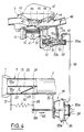
- Figure 4 is a partial sectional view in elevation showing the position of the shutter control means shown in Figures 3, 3A and 3B, when the engine is cold.
- Figure 5 is a partial sectional view in elevation showing the position of the closure flap control means shown in Figures 3, 3A and 3B, when the engine is hot.
- FIG. 6A is a functional diagram showing the circulation of gases in a Siamese tube of a device according to the invention, during the cold start of the engine.
- FIG. 6B is a functional diagram showing the circulation of the exhaust gases in a Siamese tube of a device according to the invention, during the hot operation of the engine or during a cold acceleration phase.
- Figure 6C is a cross-sectional view along C-C of Figure 6A.
- Figure 7 is a side elevational view of an exhaust device according to the invention and according to an alternative embodiment.
- FIG. 7A is a sectional view along A-A of FIG. 7.
- FIG. 8 is a top view of the exhaust device shown in FIG. 7.
- the expansion pot 5 is connected to an exhaust 6 whose outlet is constituted by a terminal exhaust pipe 7 opening to the atmosphere.
- the first exhaust pipe 2 is produced in the form of a Siamese tube with two conduits and, according to the invention, an opening and closing flap of one of the conduits of the Siamese tube 2 is placed in a portion 8 of the end of the tube 2 and connected to an opening and closing control assembly 10.
- FIG 2 there is shown the exhaust manifold 9 of a four-cylinder petrol engine comprising four pipes 11, 12, 13 and 14 respectively connected at their inlet end to the exhaust duct of the first, of the second, third and fourth cylinder and joined together at the outlet part of the manifold which has a partition 17, so that the pipes 11 and 14 of the first and fourth cylinders open into a first chamber 16a delimited by the partition 17 and the pipes 12 and 13 connected to the second and third cylinders in a second chamber 16b delimited by the partition 17.
- the outlet part of the exhaust manifold 9 comprises a connection flange 15 intended to ensure the fixing of the exhaust line by means of the connection piece 1 called a ball joint.
- the ball joint 1 is made integral with the end of the Siamese tube 2 by means of the portion 8 of this tube in which the closure flap of one of the conduits of the Siamese tube 2 is mounted.
- the Siamese tube 2 is constituted by a tubular metallic element whose internal volume is separated into two parts 18a and 18b of semi-circular section by a transverse partition 19 arranged diametrically in the tube 2.
- the partition 19 extends up to level of the entry part of the ball joint 1, so that when the siamese tube 2 is connected to the exhaust manifold 9, via the ball joint 1 and the flange 15, the chamber 16a of the manifold is in communication with the conduit 18a of the Siamese tube and the chamber 16b with the conduit 18b, as shown by the arrows 21 in dotted lines in FIG. 2.
- the end of the Siamese tube 2 opposite its connection portion to the ball joint 1 is connected to the casing of the catalytic converter 3, so that the conduits 18a and 18b of the tube 2 both open into the volume internal of the catalytic converter 3 occupied by a mass of catalyst with a large contact surface, as described above.
- the partition 19 has a through opening 20 inside the end 8 of the envelope of the tube 2, the semi-circular shape of which is visible in FIG. 3B.
- a closing flap 23 of the conduit 18b is mounted articulated by means of a pin 24 in the wall of the end part 8 of the Siamese tube 2.
- the flap 23 of semi-circular shape has a diameter greater than the diameter of the opening 20 in order to ensure complete covering of the edge of the opening in its raised position shown diagrammatically by the end 25a of the arrow 25 which symbolizes the displacements by pivoting the closing flap 23, in FIG. 3.
- the end 25b of the arrow 25 corresponds to the movement of the flap 23 in the closed position, as shown in FIG. 3, the edge of the flap then coming into contact with the internal surface of the conduit 18b of the Siamese tube 2.
- the outer edge of the flap 23 may have the shape of an ellipse with low eccentricity.
- One end of the axis 23 rotatably engaged in the wall of the end 8 of the tube 2 is protected externally by a casing 26 and the other end of the axis is connected to a control lever 28.
- the end of the axis 24 connected to the lever 28 crosses the wall of the end 8 of the tube 2, at a bearing 27 ensuring the rotary mounting of the axis 24 and a sealed passage from the end of the axis through the end wall 8 of the tube 2.
- the flap 23 is rigidly fixed on the axis 24, for example by means of rivets 29.
- the flap 23 is in the open position of the conduit 18b, which corresponds to the closing of the opening 20 of the partition 19, the outer edge of the flap being in the position indicated by the end 25a of arrow 25.
- the flap 23 is in the closed position of the conduit 18b of the siamese tube 2 and therefore in the open position of the opening 20 of the partition 19.
- the lever 28 secured to the axis 24 of the flap 23 is connected, in the vicinity of its end opposite the axis 24, to a first end of a helical return spring 30, the second end of which is connected to a fixed support 31 integral with the end portion 8 of the tube 2.
- the spring 30 tends to return the lever 28 in a direction corresponding to the opening of the conduit 18b, that is to say to the closing of the opening 20 of the partition 19 (arrow 32 in Figure 5).
- the end of the lever 28 opposite the axis 24 is also connected to the rod 33 of a pneumatic cylinder 34, the internal chamber of which is sealed in two parts by a partition 35 comprising a rigid central part 35a and a part flexible device 35b allowing movement of the partition 35 inside the room.
- the cylinder 34 is fixed on a support 37 integral with the Siamese tube 2, in the vicinity of its end part 8 containing the flap 23.
- the rod 33 is fixed at its end opposite to the lever 28, to the rigid part 35a of the partition 35 on which is also fixed a return spring 39 compressed and exerting pressure on the partition 35 so as to move the rod 33 in the direction of arrow 32 and to keep the flap in the closed position of the opening 20 of the partition 19.
- the springs 30 and 39 thus act in the same direction, so as to keep the shutter in the closed position of the opening 20.
- FIG. 4 In the upper part of Figures 4 and 5, there is shown the upper part of the cylinder block 40 of a gasoline engine, at the level of a cylinder 41 in which a piston 42 moves.
- the upper part of the cylinder 41 is closed by the cylinder head 43 in which are machined, at the upper part of the cylinder 41, an air and fuel mixture intake duct 44 and an exhaust duct 45.
- the exhaust manifold 9 is fixed to the cylinder head so as to put the exhaust duct 45 in communication with the tubing of the cylinder 41.
- An intake valve 45 and an exhaust valve 46 are mounted in the cylinder head 43 so as to ensure the opening and closing of the intake 44 and exhaust 45 conduits, respectively.
- a fuel injector 47 opens at the inlet of the intake pipe 44, slightly downstream of the valve 45.
- a butterfly valve comprising a shutter 48 is disposed in the intake pipe upstream of the injector 47.
- the opening of the butterfly shutter 48 is controlled, in the usual way, by the vehicle accelerator.
- the cylinder block 40 includes a jacket 50 in which the engine cooling water circulates.
- thermovalve 51 is tightly fixed in a threaded bore passing through a part of the cylinder block 40, so that the end of the thermovalve 51 constituted by a thermosensitive element 52 is in the immediate vicinity of the water circulating in the lining 50 with which it very quickly becomes in thermal equilibrium.
- thermovalve 51 comprises a chamber 51a in which a valve shutter 53 moves, having one end connected to the heat-sensitive element 52.
- the thermovalve 51 comprises a first nozzle 55 and a second nozzle 57 opening one and the other into the interior volume of the body of the thermovalve 51, in which the shutter drawer 53 moves.
- the nozzle 57 is connected by a tube 56 to the intake duct 44, downstream of the butterfly valve 48.
- the second nozzle 57 is connected by a tube 58 to the chamber of the pneumatic cylinder 34, on the side opposite to the rod 33.
- thermovalve 51 is pierced with an opening 59 in the vicinity of its outer end allowing its interior volume to be brought into the atmosphere.
- the heat-sensitive element 52 places the shutter with drawer 53 in its position shown on Figure 4. This shutter has an enlarged end portion 53a which is then in position closing the opening 59 for venting the internal volume of the body of the thermovalve 51.
- the chamber of the pneumatic cylinder 34 is placed in communication via the tube 58, of the internal volume of the thermovalve 51 and of the tube 56 with the intake duct 44 downstream of the butterfly valve 48.
- the chamber of the cylinder 34 is subjected to the depression in the intake duct, which causes the wall 35 and the rod 33 to move, in the direction of the arrow 60.
- the spring 39 is compressed, the end of the lever 28 connected to the rod 33 moves in the direction of arrow 60 and the spring 30 expands.
- the flap 23 is placed in the closed position of the conduit 18b, that is to say in the open position of the orifice 20.
- the conduit 2 of the device shown in FIGS. 6A and 6B is produced in the form of a Siamese tube comprising two superimposed conduits 18a, 18b separated by a partition 19.
- the heat losses are reduced, insofar as only one duct is in operation, which correspondingly reduces the surfaces for exchange with the outside atmosphere.
- the transfer time is reduced and the gas flow is concentrated on a smaller section of the mass of catalyst 61 disposed inside the casing 3 of the catalytic converter.
- This circulation of gases in a single conduit of the Siamese tube makes it possible to considerably reduce the time required to warm up the catalyst, this catalyst passing for example from an ambient temperature of 20 ° C to its activation temperature of 300 ° C.
- the anti-pollution tests are carried out after immobilization of the vehicle for a period of 12 hours at an ambient temperature of 20 to 25 °. Pollutant gas emissions are analyzed and measured (in g / km) during the catalyst warm-up phase.
- thermosensitive element 52 of the thermovalve 51 moves the shutter drawer 53 which comprises an enlarged part 53b, so that this part 53b interrupts the communication between the part of the interior volume of the body of the thermovalve 51 in which the nozzle 55 opens and the part of the body in which the nozzle 57 opens.
- the exhaust gases are then capable of circulating inside the two conduits 18a and 18b of the tube 2 simultaneously, as shown in FIG. 6B and shown diagrammatically by the arrows 65.
- the gases from cylinders 1 and 4 are conveyed to the catalytic converter 3 where they come into contact with the mass of catalyst 61 via the conduit 18a.
- the gases from cylinders 2 and 3 are routed through line 18b.
- the engine can thus develop its maximum power.
- the Siamese tube 2 has heated up as a whole also by thermal conduction.
- the engine is no longer in its starting phase, the mixture is less enriched with fuel and the quantity of polluting gases emitted is reduced.
- the control device described and shown in FIG. 4 allows the engine to develop significant power, in the event that the driver of the vehicle deems it necessary and accelerates fully to obtain this power.
- the butterfly valve 48 opens fully and the vacuum in the intake manifold and in particular in the part of the intake duct 44 located downstream of the butterfly valve 48 decreases to a close value. of the value zero.
- the pneumatic cylinder 34 no longer ensures the retention of the rod 33 in the direction of the arrow 33 and the spring 30 ensures the return of the lever 28 in the direction of the arrow 32, as shown in Figure 5.
- the flap 23 comes apply in the closed position of the opening 20 and the device operates as in the case where the engine is hot, the gases flowing simultaneously in the conduits 18a and 18b, as shown in FIG. 6B.
- the engine can then develop the requested power.
- the mass of catalyst 61 is not yet at its activation temperature and that consequently, the polluting gases contained in the exhaust gases are not eliminated in significant quantity.
- the gas flow rate is important and the time required to warm up the catalyst is reduced and with it, the emissions of polluting gases.
- FIGS. 7, 7A and 8 a variant of an exhaust device according to the invention is shown, comprising a ball joint 62 for connecting to the exhaust manifold of an engine, two parallel pipes 63a and 63b connected to the 'one of their ends by a bypass line 64 and a catalytic converter 65 containing a mass of catalyst 66 into which open the end portions of the lines 63a and 63b opposite the bypass 64 and the ball joint 62.
- a shutter 67 for closing the conduit 63b is placed at the branch 64 so that in the open position of the conduit 63b, the shutter 67 closes the branch 64.
- the shutter 67 is controlled by a device as shown in the Figures 4 and 5.
- FIGS. 7, 7A and 8 are identical to the operation and the advantages described above in the case of an exhaust device with a Siamese tube.
- the temperature setting up of the conduit 63b in which the exhaust gases are not put into circulation takes place more slowly and less easily than in the case of a tube device Siamese.
- the heat losses are higher, insofar as the external contact and exchange surface of the conduits, with identical passage sections, is greater than in the case of a Siamese tube with two conduits.
- the device makes it possible to effectively remove polluting gases during the engine start-up phase and to ensure operation at full power both when the engine is cold and when the engine is hot.
- the device is compact and uses simple control means and whose operation is very safe.
- the housing in which is mounted the closing and opening flap of one of the exhaust pipe conduits can be constituted not only by an initial part of the exhaust pipe but also by a suitable housing on the engine exhaust manifold to which the end of the exhaust pipe is connected.
- the opening and closing flap of one of the exhaust pipe conduits can be controlled not only in the manner which has been described but also by a temperature probe placed in the mass of the catalyst and connected to a circuit of control of the opening and closing of the shutter.
- Putting the shutter in the open position in order to allow the passage of gases in the two exhaust pipe conduits can be ensured by a device ensuring a time delay and allowing opening after a certain time interval following start-up. of the motor.
- the invention can use catalytic converters of different type, that these pots contain a catalyst allowing oxidation or reduction of the polluting gases contained in the exhaust gases or even that they are produced in the form of 'a three-way structure.
- the invention applies to any device for removing and treating the exhaust gases of an engine, whether this engine is used on a road vehicle, on any other type of vehicle or on a fixed installation.
Description
L'invention concerne un dispositif d'évacuation et de traitement anti-pollution des gaz d'échappement d'un moteur.The invention relates to a device for evacuation and anti-pollution treatment of exhaust gases from an engine.
A l'heure actuelle, dans la plupart des pays industrialisés, l'homologation d'un nouveau type de véhicule doit être précédée par des essais permettant de contrôler le respect de valeurs limites, en ce qui concerne l'émission de matières polluantes contenues dans les gaz d'échappement, en particulier dans le cas des véhicules à moteur à essence.At present, in most industrialized countries, the approval of a new type of vehicle must be preceded by tests enabling compliance with limit values to be checked with regard to the emission of pollutants contained in exhaust gases, in particular in the case of gasoline-powered vehicles.
Les principales matières polluantes dont on assure le contrôle sont des gaz tels que l'oxyde de carbone, les hydrocarbures et les oxydes de l'azote.The main pollutants that are controlled are gases such as carbon monoxide, hydrocarbons and nitrogen oxides.
Ces essais et contrôles anti-pollution sont devenus de plus en plus sévères, si bien qu'actuellement, il est nécessaire de recourir à l'utilisation d'un pot catalytique intercalé sur la ligne d'échappement des gaz pour satisfaire les normes imposées par la réglementation en vigueur.These anti-pollution tests and controls have become more and more stringent, so that currently, it is necessary to resort to the use of a catalytic converter interposed on the exhaust gas line to meet the standards imposed by applicable regulations.
Les pots catalytiques utilisés actuellement qui sont intercalés sur la ligne d'échappement entre les tubulures d'échappement du moteur et le pot de détente sont constitués par une enveloppe métallique contenant une masse de matériau catalyseur présentant une très grande surface de contact pour les gaz d'échappement traversant le pot catalytique.The catalytic converters currently used which are interposed on the exhaust line between the exhaust pipes of the engine and the expansion pot consist of a metal casing containing a mass of catalyst material having a very large contact surface for the gases exhaust passing through the catalytic converter.
Les gaz polluants tels que les gaz mentionnés ci-dessus sont éliminés par une réaction chimique d'oxydation ou de réduction, au contact du catalyseur, dès que celui-ci a été porté par les gaz d'échappement à une température suffisante pour assurer le démarrage de la réaction chimique.The polluting gases such as the gases mentioned above are eliminated by a chemical reaction of oxidation or reduction, in contact with the catalyst, as soon as the latter has been brought by the exhaust gases to a temperature sufficient to ensure the start of the chemical reaction.
Cette température minimale du catalyseur est généralement comprise entre 250 et 300°C suivant l'âge du catalyseur. Le fonctionnement correct du pot catalytique demande également un bon réglage du mélange air-essence.This minimum catalyst temperature is generally between 250 and 300 ° C depending on the age of the catalyst. The correct functioning of the catalytic converter also requires a good adjustment of the air-fuel mixture.
En outre, la température du catalyseur doit rester inférieure à une température limite au-delà de laquelle le catalyseur commence à être détérioré, au contact des gaz d'échappement.In addition, the temperature of the catalyst must remain below a limit temperature above which the catalyst begins to deteriorate, in contact with the exhaust gases.
La masse de matériau catalytique est généralement constituée par un support en matière céramique ou métallique comprenant des milliers de petits canaux traversés par les gaz d'échappement et recouverts d'une couche d'alumine qui multiplie par environ 7000 la surface active du catalyseur, c'est-à-dire la surface du catalyseur venant en contact avec les gaz. Sur la couche d'alumine, on dépose 2 à 3 g de métaux précieux, généralement du platine et du rodhium qui permettent d'accélérer les vitesses des réactions chimiques d'élimination des gaz polluants.The mass of catalytic material is generally constituted by a ceramic or metallic support comprising thousands of small channels crossed by the exhaust gases and covered with a layer of alumina which multiplies by approximately 7000 the active surface of the catalyst, c that is to say the surface of the catalyst coming into contact with the gases. On the alumina layer, 2 to 3 g of precious metals are deposited, generally platinum and rodhium, which make it possible to accelerate the speeds of chemical reactions for the elimination of polluting gases.
Compte tenu du mode de fonctionnement d'un pot catalytique, il est nécessaire de placer le pot catalytique le plus près possible du moteur de manière à réduire le temps d'amorçage du catalyseur après un démarrage du moteur froid, les gaz d'échappement parvenant alors au pot catalytique avec un minimum de déperdition calorifique.Given the operating mode of a catalytic converter, it is necessary to place the catalytic converter as close as possible to the engine so as to reduce the time for priming the catalyst after starting the engine cold, the exhaust gases reaching then to the catalytic converter with a minimum of heat loss.
En revanche, lorsque le moteur est utilisé à haut régime, par exemple sur un véhicule roulant sur autoroute, il est nécessaire d'éviter une trop forte montée en température du catalyseur dont la température doit rester inférieure à la limite au-delà de laquelle il commence à se détériorer. Il est donc nécessaire d'éloigner suffisamment le pot catalytique des tubulures d'échappement du moteur pour éviter l'envoi de gaz à trop haute température sur la masse du catalyseur.On the other hand, when the engine is used at high speed, for example on a vehicle traveling on a motorway, it is necessary to avoid an excessive rise in temperature of the catalyst, the temperature of which must remain below the limit beyond which it begins to deteriorate. It is therefore necessary to move the catalytic converter far enough from the engine exhaust pipes to avoid sending gases at too high a temperature on the mass of the catalyst.
Il est également nécessaire de tenir compte de la place disponible sous le plancher du véhicule pour choisir l'emplacement du pot catalytique.It is also necessary to take into account the space available under the vehicle floor when choosing the location of the catalytic converter.
Il en résulte donc des difficultés en ce qui concerne le choix d'une disposition optimale pour le pot catalytique d'un véhicule.This therefore results in difficulties as regards the choice of an optimal arrangement for the catalytic converter of a vehicle.
Suivant les performances recherchées pour le moteur, la ligne d'échappement peut être conçue de différentes manières.Depending on the performance sought for the engine, the exhaust line can be designed in different ways.
Dans le cas des moteurs peu performants, les quatre tubulures associées à chacun des cylindres du moteur sont reliées à un seul tuyau d'échappement sur lequel est disposé le pot de détente et éventuellement le pot catalytique du moteur. Cette disposition est connue sous l'appellation de "quatre dans un".In the case of poorly performing engines, the four pipes associated with each of the engine cylinders are connected to a single exhaust pipe on which is disposed the expansion pot and possibly the catalytic converter of the engine. This arrangement is known as "four in one".
Dans le cas des moteurs plus performants, on utilise une conception connue sous le nom de "quatre dans deux" dans laquelle deux des tubulures d'échappement associées à deux cylindres du moteur sont reliées à un premier tuyau d'échappement et les deux autres tubulures associées aux deux autres cylindres du moteur, à un second tuyau d'échappement. Les deux tuyaux d'échappement sont reliés entre eux en amont du pot de détente, et par exemple au niveau d'un pot catalytique.In the case of more efficient engines, a design known as "four in two" is used in which two of the exhaust pipes associated with two engine cylinders are connected to a first exhaust pipe and the other two pipes associated with the other two cylinders of the engine, with a second exhaust pipe. The two exhaust pipes are interconnected upstream of the expansion pot, and for example at the level of a catalytic converter.
La disposition "quatre dans deux" a été améliorée en utilisant un tube dit "tube siamois" qui est séparé en son milieu par une cloison plane disposée suivant un plan diamétral. Le tube siamois est équivalent à deux tubes d'une ligne d'échappement, chacun des conduits séparés par la cloison plane étant relié à deux tubulures d'échappement associées à deux cylindres du moteur.The "four in two" arrangement has been improved by using a tube called a "Siamese tube" which is separated in its middle by a plane partition arranged along a diametrical plane. The Siamese tube is equivalent to two tubes of an exhaust line, each of the conduits separated by the flat partition being connected to two exhaust pipes associated with two engine cylinders.
Les lignes d'échappement comportant un tube siamois sont plus faciles à loger sous le plancher du véhicule et entraînent des déperditions de chaleur plus faibles que deux conduits séparés, dans la mesure où les deux conduits du tube siamois ont une paroi commune et une surface d'échange avec l'extérieur d'une valeur plus faible pour une section des conduits équivalente.Exhaust systems with a Siamese tube are easier to accommodate under the vehicle floor and cause more heat loss weaker than two separate conduits, insofar as the two conduits of the Siamese tube have a common wall and a surface for exchange with the outside of a lower value for an equivalent cross-section of the conduits.
Dans le cas d'une ligne d'échappement à deux conduits parallèles, on a déjà proposé d'associer un pot catalytique à chacun des conduits reliés à un ensemble de cylindres du moteur.In the case of an exhaust line with two parallel conduits, it has already been proposed to associate a catalytic converter with each of the conduits connected to a set of engine cylinders.
Un dispositif à clapets ou vannes placé à l'entrée ou à la sortie de l'un des pots catalytiques permet d'interrompre la circulation des gaz d'échappement dans l'un des deux conduits parallèles et de faire passer l'ensemble des gaz d'échappement du moteur dans l'autre conduit sur lequel est placé le second pot catalytique, les deux conduits parallèles étant reliés entre eux en amont des deux pots catalytiques.A valve or valve device placed at the inlet or outlet of one of the catalytic converters makes it possible to interrupt the circulation of the exhaust gases in one of the two parallel conduits and to pass all the gases engine exhaust in the other conduit on which the second catalytic converter is placed, the two parallel conduits being interconnected upstream of the two catalytic converters.
Un tel dispositif est cependant relativement plus complexe et plus coûteux qu'un dispositif à un seul pot catalytique.Such a device is however relatively more complex and more expensive than a device with a single catalytic converter.
Lors d'un démarrage à froid du moteur, l'ensemble des gaz est dirigé dans un seul des deux conduits parallèles et traverse l'un des deux pots catalytiques. La masse de catalyseur de ce pot catalytique s'échauffe plus vite et l'activation du catalyseur est donc réalisée plus rapidement. Cependant, la masse de catalyseur du second pot catalytique reste à basse température et lors de l'ouverture de la vanne du second conduit, les gaz du moteur viennent en contact avec un catalyseur à basse température, si bien que les réactions d'élimination des gaz polluants ne se produisent pas pendant quelque temps. Cet inconvénient est atténué par le fait que les gaz d'échappement renferment des quantités plus faibles de gaz polluants, lorsque le moteur est chaud, dans la mesure où le mélange injecté dans le moteur est moins riche en combustible. En outre, l'échauffement du second pot catalytique est réalisé avec des gaz à haute température, si bien que son temps d'échauffement jusqu'à sa température d'activation se trouve réduit.During a cold start of the engine, all of the gases are directed into one of the two parallel conduits and pass through one of the two catalytic converters. The mass of catalyst in this catalytic converter heats up faster and the activation of the catalyst is therefore carried out more quickly. However, the mass of catalyst in the second catalytic converter remains at low temperature and when the valve in the second pipe is opened, the gases from the engine come into contact with a catalyst at low temperature, so that the reactions for eliminating polluting gases do not occur for some time. This drawback is mitigated by the fact that the exhaust gases contain smaller quantities of polluting gases, when the engine is hot, insofar as the mixture injected into the engine is less rich in fuel. In addition, the heating of the second catalytic converter is produced with high temperature gases, so that its heating time up to its activation temperature is reduced.
Dans le DE-A-2.104.711, on a proposé un dispositif permettant d'accélérer le chauffage d'une masse de catalyseur d'un pot catalytique dans une phase de démarrage du moteur.In DE-A-2.104.711, a device has been proposed making it possible to accelerate the heating of a mass of catalyst in a catalytic converter in an engine start-up phase.
Le conduit d'échappement comporte un embranchement au niveau duquel il se sépare en un premier conduit traversant la masse du catalyseur et en un second conduit débouchant dans l'enveloppe du catalyseur et une vanne d'ouverture ou de fermeture des conduits.The exhaust duct has a branch at which it separates into a first duct passing through the mass of the catalyst and into a second duct opening into the envelope of the catalyst and a valve for opening or closing the ducts.
Un tel dispositif qui ne comporte pas deux tuyaux d'échappement distincts reliés chacun, à l'une de leurs extrémités, à deux tubulures d'échappement du moteur et, à leur autre extrémité, au pot catalytique, ne pourrait être utilisé sur les moteurs à haute performance.Such a device, which does not have two separate exhaust pipes, each connected at one of their ends to two engine exhaust pipes and, at their other end, to the catalytic converter, could not be used on engines high performance.
En outre, la vanne d'ouverture et de fermeture des conduits est commandée en fonction de la température du moteur uniquement, si bien que le niveau de puissance demandé au moteur n'est pas pris en compte. Enfin, les gaz d'échappement n'assurent le chauffage de la masse du catalyseur, dans la phase de démarrage, qu'à travers la paroi du premier conduit.In addition, the valve for opening and closing the ducts is controlled as a function of the engine temperature only, so that the power level requested from the engine is not taken into account. Finally, the exhaust gases only heat the mass of the catalyst, in the start-up phase, through the wall of the first duct.
Dans le FR-A-2.018.123, on a proposé un dispositif de post-combustion d'un moteur qui est relié au pot d'échappement par une conduite secondaire débouchant dans la ligne d'échappement principale reliée aux tubulures du moteur. Une vanne commandée en fonction de la puissance demandée au moteur permet de fermer la partie de la ligne d'échappement reliée aux tubulures quand le moteur fonctionne à faible puissance. Ce dispositif n'est pas conçu pour assurer un fonctionnement satisfaisant d'un pot catalytique lors du démarrage à froid du moteur.In FR-A-2.018.123, an afterburner of an engine has been proposed which is connected to the exhaust pipe by a secondary pipe opening into the main exhaust line connected to the pipes of the engine. A valve controlled according to the power required from the engine makes it possible to close the part of the exhaust line connected to the pipes when the engine is running at low power. This device is not designed to ensure satisfactory operation of a catalytic converter during cold starting of the engine.
Les dispositifs suivant l'art anté-rieur ne permettent pas d'obtenir des conditions optimales, aussi bien en ce qui concerne le coût de construction du dispositif d'échappement que les conditions de fonctionnement de ce dispositif, lors du démarrage à froid du moteur et lors de son fonctionnement à chaud.The devices according to the prior art do not allow optimal conditions to be obtained, both with regard to the cost of construction of the exhaust device and the operating conditions of this device, when the engine is cold started and during its hot operation.
Le but de l'invention est donc de proposer un dispositif d'évacuation et de traitement antipollution des gaz d'échappement d'un moteur comportant au moins deux conduits parallèles reliés chacun à l'une de ses extrémités à une partie des tubulures d'échappement fixées à la sortie des cylindres du moteur et à son autre extrémité à au moins un pot catalytique constitué par une enveloppe renfermant une masse de matériau catalyseur permettant une élimination des gaz nocifs contenus dans les gaz d'échappement du moteur parvenant au contact du catalyseur, ce dispositif étant relativement simple et peu coûteux et permettant d'assurer une bonne efficacité du pot catalytique quelles que soient les conditions de fonctionnement du moteur.The object of the invention is therefore to propose a device for evacuation and anti-pollution treatment of exhaust gases from an engine comprising at least two parallel conduits each connected at one of its ends to a part of the pipes of exhaust fixed at the outlet of the engine cylinders and at its other end to at least one catalytic converter constituted by an envelope containing a mass of catalyst material allowing elimination of the harmful gases contained in the engine exhaust gases coming into contact with the catalyst , this device being relatively simple and inexpensive and making it possible to ensure good efficiency of the catalytic converter whatever the operating conditions of the engine.
Dans ce but :
- les deux conduits parallèles sont reliés à une seule enveloppe contenant le matériau catalyseur et débouchent dans l'enveloppe suivant deux zones adjacentes, de manière à diriger deux flux parallèles de gaz d'échappement dans deux parties adjacentes de la masse de matériau catalyseur,
- et l'un des conduits comporte un volet de fermeture relié à des moyens de commande assurant la fermeture ou l'ouverture du conduit pendant la phase de démarrage à froid du moteur, suivant la puissance demandée au moteur et maintenant le volet en position d'ouverture, lorsque le moteur est chaud, la position de fermeture du premier conduit assurant une mise en communication des deux conduits, pour l'évacuation des gaz du premier conduit.
- the two parallel conduits are connected to a single envelope containing the catalyst material and open into the envelope in two adjacent zones, so as to direct two parallel flows of exhaust gas into two adjacent parts of the mass of catalyst material,
- and one of the conduits comprises a closing flap connected to control means ensuring the closing or opening of the conduit during the cold start phase of the engine, according to the power demanded of the engine and keeping the flap in the position of opening, when the engine is hot, the closed position of the first conduit ensuring communication between the two conduits, for the evacuation of gases from the first conduit.
Afin de bien faire comprendre l'invention, on va maintenant décrire, à titre d'exemple non limitatif, en se référant aux figures jointes en annexe, un mode de réalisation d'un dispositif d'évacuation et de traitement antipollution des gaz d'échappement d'un moteur suivant l'invention.In order to clearly understand the invention, a description will now be given, by way of nonlimiting example, with reference to the attached figures, of a method of realization of a device for evacuation and anti-pollution treatment of exhaust gases from an engine according to the invention.
La figure 1 est une vue générale en perspective éclatée d'une ligne d'échappement présentant les caractéristiques suivant l'invention.Figure 1 is a general exploded perspective view of an exhaust line having the characteristics according to the invention.
La figure 2 est une vue à plus grande échelle d'une partie de la ligne d'échappement représentée sur la figure 1 comportant un tuyau d'échappement du type tube siamois relié à un pot catalytique.Figure 2 is an enlarged view of part of the exhaust line shown in Figure 1 having an exhaust pipe of the Siamese tube type connected to a catalytic converter.
La figure 3 est une vue en coupe axiale à plus grande échelle d'une partie du tuyau d'échappement à double conduit représenté sur la figure 2 dans laquelle est placé un volet de fermeture de l'un des conduits.FIG. 3 is a view in axial section on a larger scale of a part of the dual-duct exhaust pipe shown in FIG. 2 in which a closure flap of one of the ducts is placed.
La figure 3A est une vue suivant A-A de la figure 3.FIG. 3A is a view along A-A of FIG. 3.
La figure 3B est une vue suivant B-B de la figure 3.FIG. 3B is a view along B-B of FIG. 3.
La figure 4 est une vue en coupe partielle et en élévation montrant la position des moyens de commande du volet de fermeture représenté sur les figures 3, 3A et 3B, lorsque le moteur est froid.Figure 4 is a partial sectional view in elevation showing the position of the shutter control means shown in Figures 3, 3A and 3B, when the engine is cold.
La figure 5 est une vue en coupe partielle et en élévation montrant la position des moyens de commande du volet de fermeture représenté sur les figures 3, 3A et 3B, lorsque le moteur est chaud.Figure 5 is a partial sectional view in elevation showing the position of the closure flap control means shown in Figures 3, 3A and 3B, when the engine is hot.
La figure 6A est un schéma fonctionnel montrant la circulation des gaz dans un tube siamois d'un dispositif suivant l'invention, pendant le démarrage à froid du moteur.FIG. 6A is a functional diagram showing the circulation of gases in a Siamese tube of a device according to the invention, during the cold start of the engine.
La figure 6B est un schéma fonctionnel montrant la circulation des gaz d'échappement dans un tube siamois d'un dispositif suivant l'invention, pendant le fonctionnement à chaud du moteur ou pendant une phase d'accélération à froid.FIG. 6B is a functional diagram showing the circulation of the exhaust gases in a Siamese tube of a device according to the invention, during the hot operation of the engine or during a cold acceleration phase.
La figure 6C est une vue en coupe transversale suivant C-C de la figure 6A.Figure 6C is a cross-sectional view along C-C of Figure 6A.
La figure 7 est une vue latérale en élévation d'un dispositif d'échappement suivant l'invention et suivant une variante de réalisation.Figure 7 is a side elevational view of an exhaust device according to the invention and according to an alternative embodiment.
La figure 7A est une vue en coupe suivant A-A de la figure 7.FIG. 7A is a sectional view along A-A of FIG. 7.
La figure 8 est une vue de dessus du dispositif d'échappement représenté sur la figure 7.FIG. 8 is a top view of the exhaust device shown in FIG. 7.
Sur la figure 1, on voit l'ensemble d'une ligne d'échappement d'un véhicule automobile comportant, à l'une de ses extrémités, une pièce de raccordement 1 d'un premier tuyau d'échappement 2 au collecteur d'échappement du moteur et un pot catalytique 3 raccordé au premier moyen d'échappement 2 et à un second tuyau 4 lui-même relié à un pot de détente 5.In Figure 1, we see the assembly of an exhaust line of a motor vehicle comprising, at one of its ends, a connecting
Le pot de détente 5 est relié à un pot d'échappement 6 dont la sortie est constituée par un tuyau d'échappement terminal 7 débouchant à l'atmosphère.The
Comme il sera expliqué de manière plus détaillée dans la suite du texte, le premier tuyau d'échappement 2 est réalisé sous la forme d'un tube siamois à deux conduits et, suivant l'invention, un volet d'ouverture et de fermeture de l'un des conduits du tube siamois 2 est placé dans une portion 8 d'extrémité du tube 2 et relié à un ensemble de commande d'ouverture et de fermeture 10.As will be explained in more detail in the remainder of the text, the
Sur la figure 2, on a représenté le collecteur d'échappement 9 d'un moteur à essence à quatre cylindres comportant quatre tubulures 11, 12, 13 et 14 reliées respectivement à leur extrémité d'entrée au conduit d'échappement du premier, du second, du troisième et du quatrième cylindre et réunies entre elles au niveau de la partie de sortie du collecteur qui comporte une cloison de séparation 17, de manière que les tubulures 11 et 14 du premier et du quatrième cylindres débouchent dans une première chambre 16a délimitée par la cloison 17 et les tubulures 12 et 13 reliées au deuxième et au troisième cylindres dans une seconde chambre 16b délimitée par la cloison 17. La partie de sortie du collecteur d'échappement 9 comporte une bride de raccordement 15 destinée à assurer la fixation de la ligne d'échappement par l'intermédiaire de la pièce de raccordement 1 appelée rotule.In Figure 2, there is shown the
La rotule 1 est rendue solidaire de l'extrémité du tube siamois 2 par l'intermédiaire de la portion 8 de ce tube dans laquelle est monté le volet de fermeture de l'un des conduits du tube siamois 2.The ball joint 1 is made integral with the end of the
Le tube siamois 2 est constitué par un élément métallique tubulaire dont le volume interne est séparé en deux parties 18a et 18b à section semi-circulaire par une cloison transversale 19 disposée de manière diamétrale dans le tube 2. La cloison 19 se prolonge jusqu'au niveau de la partie d'entrée de la rotule 1, de manière que lors du raccordement du tube siamois 2 sur le collecteur d'échappement 9, par l'intermédiaire de la rotule 1 et de la bride 15, la chambre 16a du collecteur soit en communication avec le conduit 18a du tube siamois et la chambre 16b avec le conduit 18b, comme il a été représenté par les flèches 21 en pointillés sur la figure 2.The
L'extrémité du tube siamois 2 opposée à sa partie de raccordement à la rotule 1 est reliée à l'enveloppe du pot catalytique 3, de manière que les conduits 18a et 18b du tube 2 débouchent l'un et l'autre dans le volume interne du pot catalytique 3 occupé par une masse de catalyseur à grande surface de contact, comme il a été décrit ci-dessus.The end of the
Sur les figures 3, 3A et 3B, on a représenté à plus grande échelle et en coupe par un plan axial, la partie d'extrémité de la rotule 1 sur laquelle est fixée l'extrémité 8 de l'enveloppe du tube siamois 2 séparé en deux conduits 18a et 18b par une cloison diamétrale 19.In Figures 3, 3A and 3B, there is shown on a larger scale and in section through an axial plane, the end portion of the
Comme il est visible en particulier sur la figure 3, la cloison 19 comporte une ouverture traversante 20 à l'intérieur de l'extrémité 8 de l'enveloppe du tube 2 dont la forme semi-circulaire est visible sur la figure 3B. Un volet de fermeture 23 du conduit 18b est monté articulé par l'intermédiaire d'un axe 24 dans la paroi de la partie d'extrémité 8 du tube siamois 2.As can be seen in particular in FIG. 3, the
Le volet 23 de forme semi-circulaire présente un diamètre supérieur au diamètre de l'ouverture 20 afin d'assurer un recouvrement complet du bord de l'ouverture dans sa position relevée schématisée par l'extrémité 25a de la flèche 25 qui symbolise les déplacements par pivotement du volet de fermeture 23, sur la figure 3.The
L'extrémité 25b de la flèche 25 correspond au déplacement du volet 23 en position de fermeture, comme représenté sur la figure 3, le bord du volet venant alors en contact avec la surface intérieure du conduit 18b du tube siamois 2.The
Pour assurer une fermeture étanche du conduit 18b dans la position basse de fermeture correspondant à l'extrémité 25b de la flèche 25, le bord extérieur du volet 23 peut présenter la forme d'une ellipse à faible excentricité.To ensure a tight closure of the
L'une des extrémités de l'axe 23 engagé à rotation dans la paroi de l'extrémité 8 du tube 2 est protégée extérieurement par un carter 26 et l'autre extrémité de l'axe est relié à un levier de commande 28.One end of the
Comme il est visible sur la figure 3A, l'extrémité de l'axe 24 reliée au levier 28 traverse la paroi de l'extrémité 8 du tube 2, au niveau d'un palier 27 assurant le montage rotatif de l'axe 24 et un passage étanche de l'extrémité de l'axe à travers la paroi d'extrémité 8 du tube 2.As can be seen in FIG. 3A, the end of the
Le volet 23 est fixé de manière rigide sur l'axe 24, par exemple par l'intermédiaire de rivets 29.The
Dans la partie inférieure des figures 4 et 5, on a représenté la partie d'extrémité du dispositif d'échappement suivant l'invention telle qu'elle a été décrite en se reportant aux figures 3, 3A et 3B.In the lower part of Figures 4 and 5, there is shown the end part of the exhaust device according to the invention as it has been described with reference to Figures 3, 3A and 3B.
Sur la figure 5, le volet 23 est en position d'ouverture du conduit 18b, ce qui correspond à la fermeture de l'ouverture 20 de la cloison 19, le bord extérieur du volet étant dans la position indiquée par l'extrémité 25a de la flèche 25.In FIG. 5, the
Au contraire, sur la figure 4, le volet 23 est en position de fermeture du conduit 18b du tube siamois 2 et donc en position d'ouverture de l'ouverture 20 de la cloison 19.On the contrary, in FIG. 4, the
Le levier 28 solidaire de l'axe 24 du volet 23 est relié, au voisinage de son extrémité opposée à l'axe 24, à une première extrémité d'un ressort hélicoïdal de rappel 30 dont la seconde extrémité est reliée à un support fixe 31 solidaire de la partie d'extrémité 8 du tube 2.The
Le ressort 30 a tendance à rappeler le levier 28 dans une direction correspondant à l'ouverture du conduit 18b, c'est-à-dire à la fermeture de l'ouverture 20 de la cloison 19 (flèche 32 sur la figure 5).The
L'extrémité du levier 28 opposée à l'axe 24 est également reliée à la tige 33 d'un vérin pneumatique 34 dont la chambre intérieure est séparée de manière étanche en deux parties par une cloison 35 comportant une partie centrale rigide 35a et une partie périphérique flexible 35b permettant les déplacements de la cloison 35 à l'intérieur de la chambre. Le vérin 34 est fixé sur un support 37 solidaire du tube siamois 2, au voisinage de sa partie d'extrémité 8 renfermant le volet 23. La tige 33 est fixée à son extrémité opposée au levier 28, à la partie rigide 35a de la cloison 35 sur laquelle est également fixé un ressort de rappel 39 comprimé et exerçant une pression sur la cloison 35 de manière à déplacer la tige 33 dans la direction de la flèche 32 et à maintenir le volet en position de fermeture de l'ouverture 20 de la cloison 19. Les ressorts 30 et 39 agissent ainsi dans le même sens, de manière à maintenir le volet en position de fermeture de l'ouverture 20.The end of the
Dans la partie supérieure des figures 4 et 5, on a représenté la partie supérieure du bloc cylindre 40 d'un moteur à essence, au niveau d'un cylindre 41 dans lequel se déplace un piston 42. La partie supérieure du cylindre 41 est fermée par la culasse 43 dans laquelle sont usinés, au niveau de la partie supérieure du cylindre 41, un conduit d'admission de mélange d'air et de carburant 44 et un conduit d'échappement 45. Le collecteur d'échappement 9 est fixé sur la culasse de manière à mettre en communication le conduit d'échappement 45 avec la tubulure du cylindre 41.In the upper part of Figures 4 and 5, there is shown the upper part of the
Une soupape d'admission 45 et une soupape d'échappement 46 sont montées dans la culasse 43 de manière à assurer l'ouverture et la fermeture des conduits d'admission 44 et d'échappement 45, respectivement.An
Un injecteur de carburant 47 débouche à l'entrée de la conduite d'admission 44, légèrement en aval de la soupape 45.A
Une vanne papillon comportant un obturateur 48 est disposée dans la conduite d'admission en amont de l'injecteur 47.A butterfly valve comprising a
L'ouverture de l'obturateur papillon 48 est commandée, de manière habituelle, par l'accélérateur du véhicule.The opening of the
Le bloc cylindre 40 comporte un chemisage 50 dans lequel circule l'eau de refroidissement du moteur.The
Une thermovanne 51 est fixée de manière étanche dans un alésage fileté traversant une partie du bloc cylindre 40, de manière que l'extrémité de la thermovanne 51 constituée par un élément thermosensible 52 se trouve au voisinage immédiat de l'eau circulant dans le chemisage 50 avec laquelle elle se met très rapidement en équilibre thermique.A
La thermovanne 51 comporte une chambre 51a dans laquelle se déplace un obturateur à tiroir 53 comportant une extrémité reliée à l'élément thermosensible 52.The
La thermovanne 51 comporte un premier ajutage 55 et un second ajutage 57 débouchant l'un et l'autre dans le volume intérieur du corps de la thermovanne 51, dans lequel se déplace le tiroir obturateur 53. L'ajutage 57 est relié par un tube 56 au conduit d'admission 44, en aval du papillon 48. Le second ajutage 57 est relié par un tube 58 à la chambre du vérin pneumatique 34, du côté opposé à la tige 33.The
De plus, le corps de la thermovanne 51 est percé d'une ouverture 59 au voisinage de son extrémité extérieure permettant de mettre son volume intérieur à l'atmosphère.In addition, the body of the
Lorsque le moteur est froid, l'eau de refroidissement circulant dans le chemisage 50 étant à une température inférieure à une certaine limite qui peut être par exemple 60°, l'élément thermosensible 52 place l'obturateur à tiroir 53 dans sa position représentée sur la figure 4. Cet obturateur comporte une partie d'extrémité élargie 53a qui se trouve alors en position de fermeture de l'ouverture 59 de mise à l'atmosphère du volume interne du corps de la thermovanne 51.When the engine is cold, the cooling water circulating in the
La chambre du vérin pneumatique 34 est mise en communication par l'intermédiaire du tube 58, du volume intérieur de la thermovanne 51 et du tube 56 avec le conduit d'admission 44 en aval du papillon 48. La chambre du vérin 34 est soumise à la dépression dans le conduit d'admission, ce qui provoque le déplacement de la paroi 35 et de la tige 33, dans le sens de la flèche 60. Le ressort 39 se comprime, l'extrémité du levier 28 reliée à la tige 33 se déplace dans le sens de la flèche 60 et le ressort 30 se dilate. Le volet 23 est placé en position de fermeture du conduit 18b, c'est-à-dire en position d'ouverture de l'orifice 20.The chamber of the
L'ensemble des gaz provenant des quatre cylindres du moteur est dévié par le volet 23 de manière à passer uniquement dans le conduit 18a du tube siamois 2, comme il est représenté sur la figure 6A sur laquelle le trajet des gaz est schématisé par les flèches 64.All of the gases coming from the four cylinders of the engine are deflected by the
Comme il est visible sur la figure 6C, le conduit 2 du dispositif représenté sur les figures 6A et 6B est réalisé sous la forme d'un tube siamois comportant deux conduits superposés 18a, 18b séparés par une cloison 19.As can be seen in FIG. 6C, the
Pendant la phase de démarrage à froid du moteur, les pertes thermiques sont réduites, dans la mesure où un seul conduit est en fonctionnement, ce qui diminue d'autant les surfaces d'échange avec l'atmosphère extérieure. En outre, le temps de transfert est réduit et le flux de gaz est concentré sur une plus faible section de la masse de catalyseur 61 disposée à l'intérieur de l'enveloppe 3 du pot catalytique.During the cold start-up phase of the engine, the heat losses are reduced, insofar as only one duct is in operation, which correspondingly reduces the surfaces for exchange with the outside atmosphere. In addition, the transfer time is reduced and the gas flow is concentrated on a smaller section of the mass of
Cette circulation des gaz dans un seul conduit du tube siamois permet de diminuer considérablement le temps de mise en température du catalyseur, ce catalyseur passant par exemple d'une température ambiante de 20°C à sa température d'activation de 300°C.This circulation of gases in a single conduit of the Siamese tube makes it possible to considerably reduce the time required to warm up the catalyst, this catalyst passing for example from an ambient temperature of 20 ° C to its activation temperature of 300 ° C.
On obtient ainsi une meilleure conversion catalytique des gaz polluants, en particulier dans les conditions de mise en oeuvre des essais anti-pollution pour l'homologation d'un moteur.A better catalytic conversion of the polluting gases is thus obtained, in particular under the conditions for implementing anti-pollution tests for the approval of an engine.
En effet, les tests anti-pollution sont effectués après une immobilisation du véhicule d'une durée de 12 heures à une température ambiante de 20 à 25°. Les émissions de gaz polluants sont analysées et dosées (en g/km) dans la phase de mise en température du catalyseur.Indeed, the anti-pollution tests are carried out after immobilization of the vehicle for a period of 12 hours at an ambient temperature of 20 to 25 °. Pollutant gas emissions are analyzed and measured (in g / km) during the catalyst warm-up phase.
De manière courante, 80% des quantités de gaz polluants produites sont émises pendant le temps que met le catalyseur pour atteindre sa température de fonctionnement.Currently, 80% of the quantities of polluting gases produced are emitted during the time it takes the catalyst to reach its operating temperature.
Lorsque le moteur est chaud (figure 5), la température de l'eau circulant dans le chemisage 50 ayant une valeur par exemple supérieure à 60°C, l'élément thermosensible 52 de la thermovanne 51 déplace le tiroir de l'obturateur 53 qui comporte une partie élargie 53b, de manière que cette partie 53b interrompe la communication entre la partie du volume intérieur du corps de la thermovanne 51 dans laquelle débouche l'ajutage 55 et la partie du corps dans laquelle débouche l'ajutage 57.When the engine is hot (FIG. 5), the temperature of the water circulating in the
Dans ce cas, quelle que soit la position du papillon 48, la chambre du vérin pneumatique 34 est mise à la pression atmosphérique par l'intermédiaire de l'ouverture 59 et de la conduite 58. La tige 33 du vérin se déplace dans le sens de la flèche 32 sous l'effet des ressorts 30 et 39.In this case, whatever the position of the
Ces ressorts assurent le déplacement et le maintien du volet 23 dans sa position de fermeture de l'orifice 20 de la paroi 19, c'est-à-dire dans sa position d'ouverture du conduit 18b du tube siamois 2.These springs ensure the movement and the maintenance of the
Les gaz d'échappement sont alors susceptibles de circuler à l'intérieur des deux conduits 18a et 18b du tube 2 simultanément, comme il est représenté sur la figure 6B et schématisé par les flèches 65.The exhaust gases are then capable of circulating inside the two
Les gaz provenant des cylindres 1 et 4 sont acheminés jusqu'au pot catalytique 3 où ils entrent en contact avec la masse de catalyseur 61 par le conduit 18a. Les gaz provenant des cylindres 2 et 3 sont acheminés par le conduit 18b.The gases from
Le moteur peut ainsi développer sa puissance maximale.The engine can thus develop its maximum power.
Il est à remarquer qu'au moment de l'ouverture du volet 23, sous l'effet de l'échauffement de l'eau de refroidissement du moteur, la masse de catalyseur 61 est déjà globalement à sa température de fonctionnement, la masse de catalyseur 61 recevant les gaz par le conduit 18a dans la phase de démarrage du moteur s'étant échauffée pendant cette phase par conduction thermique.It should be noted that when the
De même, le tube siamois 2 s'est échauffé dans son ensemble également par conduction thermique.Likewise, the
En outre, le moteur n'étant plus dans sa phase de démarrage, le mélange est moins enrichi en carburant et la quantité de gaz polluants émis est réduite.In addition, the engine is no longer in its starting phase, the mixture is less enriched with fuel and the quantity of polluting gases emitted is reduced.
En conséquence, lorsque le volet 23 passe de sa position représentée sur la figure 6A à sa position représentée sur la figure 6B, il ne se produit aucune modification sensible des conditions de fonctionnement du catalyseur, si bien que les émissions de gaz polluants sont extrêmement réduites pendant cette phase intermédiaire.Consequently, when the
Dans le cas où le moteur est froid, comme représenté sur la figure 4, l'eau circulant dans le chemisage 50 étant à une température inférieure à la température limite, par exemple 60°, le dispositif de commande décrit et représenté sur la figure 4 permet au moteur de développer une puissance importante, dans le cas où le conducteur du véhicule le juge nécessaire et accélère à fond pour obtenir cette puissance.In the case where the engine is cold, as shown in FIG. 4, the water circulating in the
En effet, dans ce cas, le papillon 48 s'ouvre entièrement et la dépression dans le collecteur d'admission et en particulier dans la partie du conduit d'admission 44 située en aval de la vanne papillon 48 décroit jusqu'à une valeur proche de la valeur zéro. Le vérin pneumatique 34 n'assure plus la retenue de la tige 33 dans le sens de la flèche 33 et le ressort 30 assure le rappel du levier 28 dans le sens de la flèche 32, comme représenté sur la figure 5. Le volet 23 vient s'appliquer en position de fermeture de l'ouverture 20 et le dispositif fonctionne comme dans le cas où le moteur est chaud, les gaz circulant simultanément dans les conduits 18a et 18b, comme représenté sur la figure 6B.In this case, the
Le moteur peut alors développer la puissance demandée.The engine can then develop the requested power.
Il faut remarquer cependant que dans ce cas la masse de catalyseur 61 n'est pas encore à sa température d'activation et qu'en conséquence, les gaz polluants contenus dans les gaz d'échappement ne sont pas éliminés en quantité significative. Toutefois, dans ce cas, comme on accèlère à fond pour obtenir une forte puissance, le débit des gaz est important et le temps de mise à température du catalyseur est réduit et avec lui, les émissions de gaz polluants.It should be noted however that in this case the mass of
Sur les figures 7, 7A et 8, on a représenté une variante d'un dispositif d'échappement suivant l'invention comportant une rotule 62 de liaison au collecteur d'échappement d'un moteur, deux conduites parallèles 63a et 63b reliées à l'une de leurs extrémités par une conduite en dérivation 64 et un pot catalytique 65 renfermant une masse de catalyseur 66 dans lequel débouchent les parties d'extrémité des conduites 63a et 63b opposées à la dérivation 64 et à la rotule 62.In FIGS. 7, 7A and 8, a variant of an exhaust device according to the invention is shown, comprising a ball joint 62 for connecting to the exhaust manifold of an engine, two
Un volet 67 de fermeture du conduit 63b est placé au niveau de la dérivation 64 de manière qu'en position d'ouverture du conduit 63b, le volet 67 ferme la dérivation 64. Le volet 67 est commandé par un dispositif tel que représenté sur les figures 4 et 5.A
Le fonctionnement et les avantages du dispositif représenté sur les figures 7, 7A et 8 sont identiques au fonctionnement et aux avantages décrits précédemment dans le cas d'un dispositif d'échappement à tube siamois. Cependant, dans la phase de démarrage à froid du moteur, la mise en température du conduit 63b dans lequel les gaz d'échappement ne sont pas mis en circulation s'effectue plus lentement et moins facilement que dans le cas d'un dispositif à tube siamois. En outre, les déperditions calorifiques sont plus fortes, dans la mesure où la surface externe de contact et d'échange des conduits, à sections de passage identiques, est supérieure au cas d'un tube siamois à deux conduits.The operation and the advantages of the device shown in FIGS. 7, 7A and 8 are identical to the operation and the advantages described above in the case of an exhaust device with a Siamese tube. However, in the cold starting phase of the engine, the temperature setting up of the
Dans tous les cas cependant le dispositif permet d'assurer une élimination efficace des gaz polluants pendant la phase de démarrage du moteur et d'assurer un fonctionnement à pleine puissance aussi bien lorsque le moteur est froid que lorsque le moteur est chaud.In all cases, however, the device makes it possible to effectively remove polluting gases during the engine start-up phase and to ensure operation at full power both when the engine is cold and when the engine is hot.
En outre, le dispositif est peu encombrant et utilise des moyens de commande simples et dont le fonctionnement est très sûr.In addition, the device is compact and uses simple control means and whose operation is very safe.
Il est bien évident que l'invention ne se limite pas au mode de réalisation qui a été décrit.It is obvious that the invention is not limited to the embodiment which has been described.
C'est ainsi que le boîtier dans lequel est monté le volet de fermeture et d'ouverture de l'un des conduits du tuyau d'échappement peut être constitué non seulement par une partie initiale du tuyau d'échappement mais encore par un boîtier adapté sur le collecteur d'échappement du moteur auquel est reliée l'extrémité du tuyau d'échappement.Thus the housing in which is mounted the closing and opening flap of one of the exhaust pipe conduits can be constituted not only by an initial part of the exhaust pipe but also by a suitable housing on the engine exhaust manifold to which the end of the exhaust pipe is connected.
Le volet d'ouverture et de fermeture de l'un des conduits du tuyau d'échappement peut être commandé non seulement de la manière qui a été décrite mais encore par une sonde de température placée dans la masse du catalyseur et reliée à un circuit de commande de l'ouverture et de la fermeture du volet.The opening and closing flap of one of the exhaust pipe conduits can be controlled not only in the manner which has been described but also by a temperature probe placed in the mass of the catalyst and connected to a circuit of control of the opening and closing of the shutter.
La mise en position d'ouverture du volet afin de permettre le passage des gaz dans les deux conduits du tuyau d'échappement peut être assurée par un dispositif assurant une temporisation et permettant l'ouverture après un certain intervalle de temps suivant la mise en marche du moteur.Putting the shutter in the open position in order to allow the passage of gases in the two exhaust pipe conduits can be ensured by a device ensuring a time delay and allowing opening after a certain time interval following start-up. of the motor.
Il est bien évident que l'invention peut utiliser des pots catalytiques de type différent, que ces pots renferment un catalyseur permettant une oxydation ou une réduction des gaz polluants contenus dans les gaz d'échappement ou encore qu'ils soient réalisés sous la forme d'une structure à trois voies.It is obvious that the invention can use catalytic converters of different type, that these pots contain a catalyst allowing oxidation or reduction of the polluting gases contained in the exhaust gases or even that they are produced in the form of 'a three-way structure.
L'invention s'applique à tout dispositif d'évacuation et de traitement des gaz d'échappement d'un moteur, que ce moteur soit utilisé sur un véhicule routier, sur tout autre type de véhicule ou sur une installation fixe.The invention applies to any device for removing and treating the exhaust gases of an engine, whether this engine is used on a road vehicle, on any other type of vehicle or on a fixed installation.
Claims (10)
- Device for the discharge and anti-pollution treatment of the exhaust gases from an engine, including at least two parallel pipes (18a, 18b; 63a, 63b) each connected at one end to part of the exhaust ducts (11, 12, 13, 14) fixed to the outlet from the engine cylinders and at the other end to at least one catalyst chamber (3, 65) consisting of a casing enclosing a mass of catalytic material (61, 66) enabling the noxious gases contained in the exhaust gases from the engine coming into contact with the catalyst (61, 66) to be eliminated, characterised by the fact that:- the two parallel pipes (18a, 18b; 63a, 63b) are connected to a single casing (3, 65) containing the mass of catalytic material (61, 66) and opening out into the casing in two adjacent zones, so as to direct two parallel exhaust gas flows into two adjacent parts of the mass of catalytic material,- and that one of the pipes, or first pipe (18b; 63b) has a closing flap (23; 67) connected to control means (51, 34) providing the closing or opening of the first pipe during the cold-start phase of the engine, depending on the power required of the engine, and holding the flap (23; 67) in the open position when the engine is hot, the position in which the first pipe is closed putting the two pipes in communication with each other, so that the gases from the first pipe can be discharged.
- Device according to Claim 1, characterised by the fact that the two parallel pipes (18a, 18b) are defined within a cylindrical tubular pipe (2) by a diametral wall (19) with an axial direction.
- Device according to Claim 2, characterised by the fact that the wall (19) has an opening (20) in a zone adjacent to the end of the tubular pipe (2) connected to the engine ducts (9), the flap (23) being mounted so as to be articulated along a rectilinear edge of the opening (20) so as to be moved by pivoting between a position in which one of the parallel pipes (18b) is closed, in which it comes to bear against the wall of the pipe (18b), and an opening position in which it comes to bear against the wall (19), at the opening (20) and so as to cover it in order to close it off.
- Device according to Claim 3, characterised by the fact that the flap (23) is secured to a lever (28), disposed outside the pipe (2), so as to enable it to be actuated by the control means (51, 34).
- Device according to any one of Claims 1 to 4, characterised by the fact that the control means consist of a thermostatic valve (51) fixed to the engine block (40) of a cylinder (41) of the engine, including a heat-sensitive element (52) in thermal contact with the engine cooling water circulating in the jacket of the cylinder block (40) of the engine, a chamber communicating with the atmosphere through an opening (59), with the inlet manifold (44) to the cylinder (41) downstream of the butterfly valve (48) through a pipe (55, 56) and with the chamber of a pneumatic actuator (34) through a pipe (58) and an obturating slide (53) fixed to the heat-sensitive element (52) having two enlarged parts (53a, 53b) able either to close off the opening (59) through which the chamber of the thermostatic valve (51) is opened to atmosphere and to put the cylinder inlet manifold (44) in communication with the chamber of the pneumatic actuator (34), or to open the chamber of the thermostatic valve (51) to atmosphere and at the same time to interrupt the communication between the cylinder inlet manifold (44) and the chamber of the pneumatic actuator (34), the pneumatic actuator (34) having a stem (33) fixed to a wall (35) closing off the chamber of the pneumatic actuator (34) which is at least partially deformable, the stem (33) being connected, at its end opposite to the wall (35) of the actuator (34), to a device (28) for opening and closing the flap (23) for closing off one of the exhaust pipes (18b).
- Device according to Claim 5, characterised by the fact that the device (28) for opening and closing the flap (23) consists of a lever fixed to a pin (24) on which the flap (23) pivots and which is connected to one end of an elastic return device (30), the other end of which is connected to a support (31) fixed to at least one of the exhaust pipes (18a, 18b).
- Device according to either one of Claims 5 and 6, characterised by the fact that the wall (35) of the chamber of the pneumatic actuator (34) is connected to a helical return spring (39), the other end of which is connected to the body of the actuator (34), so as to return the stem (33) of the actuator (34) and the device (28) for operating the flap (23) to the position in which the exhaust pipe (18b) is open.
- Device according to any one of Claims 1 to 7, characterised by the fact that the flap (23) for closing off the exhaust pipe (18b) is mounted inside a housing (8) fixed to the end of the exhaust pipes connected to the engine ducts (11, 12, 13, 14).
- Device according to any one of Claims 1 to 7, characterised by the fact that the closing flap (23) is mounted inside a housing (8) fixed to an exhaust manifold (9) including the ducts (11, 12, 13, 14) from the engine, at its outlet end intended to be connected to the exhaust pipes.
- Device according to Claim 1, characterised by the fact that the exhaust pipes (63a, 63b) disposed in parallel are two separate cylindrical tubular pipes connected to one another, in the vicinity of the end at which they are connected to the ducts from the engine, by means of a diversion pipe (64), and at their other end to the casing (65) of the catalyst chamber, the flap (67) for closing off one of the pipes (63b) being mounted so as to be articulated at the diversion pipe (64), so as to be moved by pivoting between a position in which the pipe (63b) is closed and a position in which the diversion (64) is closed and the pipe (63b) is open.
Applications Claiming Priority (2)
| Application Number | Priority Date | Filing Date | Title |
|---|---|---|---|
| FR8916126A FR2655376B1 (en) | 1989-12-06 | 1989-12-06 | DEVICE FOR THE EXHAUST AND ANTI-POLLUTION TREATMENT OF EXHAUST GAS FROM AN ENGINE AND CORRESPONDING METHOD. |
| FR8916126 | 1989-12-06 |
Publications (2)
| Publication Number | Publication Date |
|---|---|
| EP0431985A1 EP0431985A1 (en) | 1991-06-12 |
| EP0431985B1 true EP0431985B1 (en) | 1993-09-01 |
Family
ID=9388214
Family Applications (1)
| Application Number | Title | Priority Date | Filing Date |
|---|---|---|---|
| EP90402813A Expired - Lifetime EP0431985B1 (en) | 1989-12-06 | 1990-10-09 | Evacuation and anti-pollution treatment device of exhaust gases of an engine |
Country Status (3)
| Country | Link |
|---|---|
| EP (1) | EP0431985B1 (en) |
| DE (1) | DE69003080T2 (en) |
| FR (1) | FR2655376B1 (en) |
Cited By (1)
| Publication number | Priority date | Publication date | Assignee | Title |
|---|---|---|---|---|
| EP3803070B1 (en) * | 2018-05-31 | 2024-02-28 | BRP-Rotax GmbH & Co. KG | Exhaust system for an engine |
Families Citing this family (2)
| Publication number | Priority date | Publication date | Assignee | Title |
|---|---|---|---|---|
| FR2678023B1 (en) * | 1991-06-18 | 1993-10-08 | Institut Francais Petrole | EXHAUST SYSTEM FOR FASTER PRIMING OF THE CATALYST. |
| US10865700B2 (en) | 2017-07-10 | 2020-12-15 | Bombardier Recreational Products Inc. | Air intake and exhaust systems for a snowmobile engine |
Family Cites Families (12)
| Publication number | Priority date | Publication date | Assignee | Title |
|---|---|---|---|---|
| FR2018123A1 (en) * | 1968-09-14 | 1970-05-29 | Honda Motor Co Ltd | |
| DE2104711C3 (en) * | 1971-02-02 | 1974-03-14 | Adam Opel Ag, 6090 Ruesselsheim | Device for catalytic post-combustion of exhaust gases from internal combustion engines |
| US3744248A (en) * | 1972-04-10 | 1973-07-10 | Gen Motors Corp | Catalytic convertor temperature control system |
| DE2237781A1 (en) * | 1972-08-01 | 1974-02-14 | Volkswagenwerk Ag | COMBUSTION ENGINE, IN PARTICULAR FOR MOTOR VEHICLES, WITH A DEVICE FOR THE REMOVAL OF HARMFUL EXHAUST COMPONENTS |
| DE2303773A1 (en) * | 1973-01-26 | 1974-08-01 | Volkswagenwerk Ag | ARRANGEMENT FOR EXHAUST GAS EXHAUST |
| US3984975A (en) * | 1975-11-10 | 1976-10-12 | General Motors Corporation | Internal combustion engine exhaust emission control |
| JPS5851212A (en) * | 1981-09-22 | 1983-03-25 | Nissan Motor Co Ltd | Exhaust gas treating device for engine controlled number-of-cylinders |
| JPS58163639U (en) * | 1982-04-27 | 1983-10-31 | 日産自動車株式会社 | Turbine bypass device for turbocharged engine |
| DE8432079U1 (en) * | 1984-11-02 | 1986-04-17 | Audi AG, 8070 Ingolstadt | Exhaust pipe |
| FR2608677B1 (en) * | 1986-12-19 | 1989-04-28 | Inst Francais Du Petrole | DEVICE AND METHOD FOR QUICK PRIMING OF AN OXIDATION CATALYST FOR A TWO-STROKE ENGINE |
| DE3736844A1 (en) * | 1987-10-30 | 1989-05-11 | Bayerische Motoren Werke Ag | METHOD FOR INFLUENCING THE TEMPERATURE OF EXHAUST GAS AND EXHAUST SYSTEM FOR CARRYING OUT THE METHOD |
| GB8817962D0 (en) * | 1988-07-28 | 1988-09-01 | Austin Rover Group | Exhaust manifold |
-
1989
- 1989-12-06 FR FR8916126A patent/FR2655376B1/en not_active Expired - Fee Related
-
1990
- 1990-10-09 EP EP90402813A patent/EP0431985B1/en not_active Expired - Lifetime
- 1990-10-09 DE DE90402813T patent/DE69003080T2/en not_active Expired - Fee Related
Cited By (1)
| Publication number | Priority date | Publication date | Assignee | Title |
|---|---|---|---|---|
| EP3803070B1 (en) * | 2018-05-31 | 2024-02-28 | BRP-Rotax GmbH & Co. KG | Exhaust system for an engine |
Also Published As
| Publication number | Publication date |
|---|---|
| FR2655376B1 (en) | 1992-04-03 |
| DE69003080T2 (en) | 1993-12-16 |
| DE69003080D1 (en) | 1993-10-07 |
| FR2655376A1 (en) | 1991-06-07 |
| EP0431985A1 (en) | 1991-06-12 |
Similar Documents
| Publication | Publication Date | Title |
|---|---|---|
| EP0913561B1 (en) | Exhaust and recirculation line of the exhaust gas of an internal combustion engine | |
| EP0519778B1 (en) | Exhaust line allowing rapid excitation of the catalytic converter | |
| EP0908606B1 (en) | Exhaust system for the engine of an automotive vehicle | |
| FR2711183A1 (en) | Exhaust gas system for an internal combustion engine with an exhaust gas turbocharger. | |
| FR2772829A1 (en) | CATALYTIC CONTAINER WITH TEMPERATURE MANAGEMENT, ESPECIALLY FOR A MOTOR VEHICLE | |
| FR2714696A1 (en) | Method for reducing hydrocarbon emissions from an internal combustion engine and device for implementing this method. | |
| FR2689933A1 (en) | An exhaust pipe of an internal combustion engine comprising a starting catalyst disposed near the engine. | |
| FR2744763A1 (en) | TURBOCHARGER COMPRISED BY THE EXHAUST GASES OF AN INTERNAL COMBUSTION ENGINE | |
| FR2483515A1 (en) | IC-engine with turbocharger - has exhaust passing to catalytic reactor by passing turbocharger during cold running | |
| EP0431985B1 (en) | Evacuation and anti-pollution treatment device of exhaust gases of an engine | |
| WO2005024193A1 (en) | Device for thermal regulation of exhaust gas | |
| EP1343963A1 (en) | Heat-exchanger module, specially designed for an exhaust gas recycling system | |
| WO2007000541A2 (en) | Additional heating device for a motor vehicle | |
| EP2163743B1 (en) | Process for treating pollutants contained in the exhaust gases of an internal combustion engine | |
| FR2752880A1 (en) | Supercharger for motor vehicle IC-engine | |
| FR2841595A1 (en) | Double skinned exhaust gas tube for use in a car exhaust has valve to allow cooling gas to flow through the annular chamber between the walls | |
| FR2859238A1 (en) | Exhaust gas thermal adjustment device for motor vehicle, has heat exchanger with openings and cover situated at surfaces of gas intake flange, cylindrical wall and outlet box that receives valve and central by-pass tube | |
| FR2731746A1 (en) | Exhaust device for removing unburnt liquid fuel from vehicle exhaust | |
| FR2729184A1 (en) | VALVE DEVICE, PARTICULARLY FOR AN EXHAUST GAS REINJECTION VALVE OF AN INTERNAL COMBUSTION ENGINE | |
| FR2919674A1 (en) | Exhaust gas orienting and regulating device for oil engine of motor vehicle, has body pivotingly mounted in manner that surface takes obturation position and collinear positions, and partition separating pipe into outlet pipes along axis | |
| FR3124220A1 (en) | EXHAUST LINE EQUIPPED WITH AN EXHAUST GAS STORAGE CHAMBER | |
| FR2717858A1 (en) | Exhaust system for purifying exhaust gases | |
| EP1118750A1 (en) | Evacuation and treatment device of exhaust gases of an internal combustion engine | |
| EP4321782A1 (en) | Mechanical double-spring poppet valve and preheating circuit including same | |
| EP0371841B1 (en) | Cooling circuit for an internal-combustion engine of a motor vehicle |
Legal Events
| Date | Code | Title | Description |
|---|---|---|---|
| PUAI | Public reference made under article 153(3) epc to a published international application that has entered the european phase |
Free format text: ORIGINAL CODE: 0009012 |
|
| 17P | Request for examination filed |
Effective date: 19910325 |
|
| AK | Designated contracting states |
Kind code of ref document: A1 Designated state(s): DE GB IT |
|
| 17Q | First examination report despatched |
Effective date: 19920624 |
|
| GRAA | (expected) grant |
Free format text: ORIGINAL CODE: 0009210 |
|
| AK | Designated contracting states |
Kind code of ref document: B1 Designated state(s): DE GB IT |
|
| ITF | It: translation for a ep patent filed |
Owner name: BUGNION S.P.A. |
|
| GBT | Gb: translation of ep patent filed (gb section 77(6)(a)/1977) |
Effective date: 19930902 |
|
| REF | Corresponds to: |
Ref document number: 69003080 Country of ref document: DE Date of ref document: 19931007 |
|
| PLBE | No opposition filed within time limit |
Free format text: ORIGINAL CODE: 0009261 |
|
| STAA | Information on the status of an ep patent application or granted ep patent |
Free format text: STATUS: NO OPPOSITION FILED WITHIN TIME LIMIT |
|
| 26N | No opposition filed | ||
| PGFP | Annual fee paid to national office [announced via postgrant information from national office to epo] |
Ref country code: DE Payment date: 19980921 Year of fee payment: 9 |
|
| PGFP | Annual fee paid to national office [announced via postgrant information from national office to epo] |
Ref country code: GB Payment date: 19981001 Year of fee payment: 9 |
|
| PG25 | Lapsed in a contracting state [announced via postgrant information from national office to epo] |
Ref country code: GB Free format text: LAPSE BECAUSE OF NON-PAYMENT OF DUE FEES Effective date: 19991009 |
|
| GBPC | Gb: european patent ceased through non-payment of renewal fee |
Effective date: 19991009 |
|
| PG25 | Lapsed in a contracting state [announced via postgrant information from national office to epo] |
Ref country code: DE Free format text: LAPSE BECAUSE OF NON-PAYMENT OF DUE FEES Effective date: 20000801 |
|
| PG25 | Lapsed in a contracting state [announced via postgrant information from national office to epo] |
Ref country code: IT Free format text: LAPSE BECAUSE OF NON-PAYMENT OF DUE FEES Effective date: 20051009 |