EP0431372A2 - Kamera und Fernbedienung dafür - Google Patents
Kamera und Fernbedienung dafür Download PDFInfo
- Publication number
- EP0431372A2 EP0431372A2 EP90121974A EP90121974A EP0431372A2 EP 0431372 A2 EP0431372 A2 EP 0431372A2 EP 90121974 A EP90121974 A EP 90121974A EP 90121974 A EP90121974 A EP 90121974A EP 0431372 A2 EP0431372 A2 EP 0431372A2
- Authority
- EP
- European Patent Office
- Prior art keywords
- exposure
- remote
- signal
- control
- bulb
- Prior art date
- Legal status (The legal status is an assumption and is not a legal conclusion. Google has not performed a legal analysis and makes no representation as to the accuracy of the status listed.)
- Granted
Links
Images




Classifications
-
- G—PHYSICS
- G03—PHOTOGRAPHY; CINEMATOGRAPHY; ANALOGOUS TECHNIQUES USING WAVES OTHER THAN OPTICAL WAVES; ELECTROGRAPHY; HOLOGRAPHY
- G03B—APPARATUS OR ARRANGEMENTS FOR TAKING PHOTOGRAPHS OR FOR PROJECTING OR VIEWING THEM; APPARATUS OR ARRANGEMENTS EMPLOYING ANALOGOUS TECHNIQUES USING WAVES OTHER THAN OPTICAL WAVES; ACCESSORIES THEREFOR
- G03B17/00—Details of cameras or camera bodies; Accessories therefor
- G03B17/38—Releasing-devices separate from shutter
- G03B17/40—Releasing-devices separate from shutter with delayed or timed action
-
- G—PHYSICS
- G03—PHOTOGRAPHY; CINEMATOGRAPHY; ANALOGOUS TECHNIQUES USING WAVES OTHER THAN OPTICAL WAVES; ELECTROGRAPHY; HOLOGRAPHY
- G03B—APPARATUS OR ARRANGEMENTS FOR TAKING PHOTOGRAPHS OR FOR PROJECTING OR VIEWING THEM; APPARATUS OR ARRANGEMENTS EMPLOYING ANALOGOUS TECHNIQUES USING WAVES OTHER THAN OPTICAL WAVES; ACCESSORIES THEREFOR
- G03B7/00—Control of exposure by setting shutters, diaphragms or filters, separately or conjointly
- G03B7/08—Control effected solely on the basis of the response, to the intensity of the light received by the camera, of a built-in light-sensitive device
- G03B7/091—Digital circuits
- G03B7/097—Digital circuits for control of both exposure time and aperture
-
- G—PHYSICS
- G03—PHOTOGRAPHY; CINEMATOGRAPHY; ANALOGOUS TECHNIQUES USING WAVES OTHER THAN OPTICAL WAVES; ELECTROGRAPHY; HOLOGRAPHY
- G03B—APPARATUS OR ARRANGEMENTS FOR TAKING PHOTOGRAPHS OR FOR PROJECTING OR VIEWING THEM; APPARATUS OR ARRANGEMENTS EMPLOYING ANALOGOUS TECHNIQUES USING WAVES OTHER THAN OPTICAL WAVES; ACCESSORIES THEREFOR
- G03B7/00—Control of exposure by setting shutters, diaphragms or filters, separately or conjointly
- G03B7/16—Control of exposure by setting shutters, diaphragms or filters, separately or conjointly in accordance with both the intensity of the flash source and the distance of the flash source from the object, e.g. in accordance with the "guide number" of the flash bulb and the focusing of the camera
-
- G—PHYSICS
- G03—PHOTOGRAPHY; CINEMATOGRAPHY; ANALOGOUS TECHNIQUES USING WAVES OTHER THAN OPTICAL WAVES; ELECTROGRAPHY; HOLOGRAPHY
- G03B—APPARATUS OR ARRANGEMENTS FOR TAKING PHOTOGRAPHS OR FOR PROJECTING OR VIEWING THEM; APPARATUS OR ARRANGEMENTS EMPLOYING ANALOGOUS TECHNIQUES USING WAVES OTHER THAN OPTICAL WAVES; ACCESSORIES THEREFOR
- G03B7/00—Control of exposure by setting shutters, diaphragms or filters, separately or conjointly
- G03B7/08—Control effected solely on the basis of the response, to the intensity of the light received by the camera, of a built-in light-sensitive device
Definitions
- This invention relates to a camera having the function of permitting a bulb exposure by remote control.
- the bulb exposure by means of a cable has presented the following problems: (1) The operability of the camera degrades and its bulkiness increases accordingly as the length of the cable increases. (2) Use of a long cable increases the possibility of wire breakage and thus lowers reliability. (3) A switch must be continuously pushed throughout the process of bulb exposure.
- Fig. 1 is a block diagram showing the functions of a camera which is arranged as a first embodiment of this invention.
- Fig. 2 is a circuit diagram showing the circuit arrangement of the first embodiment.
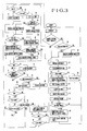
- Fig. 3 is a flow chart showing the operation of the circuit of Fig. 2.
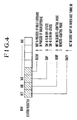
- Fig. 4 shows RAM information arranged within a microcomputer which is included in the circuit of Fig. 2.
- Fig. 5 is a block diagram showing the functions of a camera which is arranged as a second embodiment of the invention.
- Fig. 6 is a circuit diagram showing the circuit arrangement of the camera of the second embodiment.
- Fig. 7 is a flow chart showing the operation of the circuit shown in Fig. 6.
- Fig. 1 shows in a block diagram the functions of a camera arranged according to this invention as a first embodiment thereof.
- a remote-control part 102 renders a remote-control signal receiving part 101 capable of receiving a remote-control signal.
- an exposure control part 100 initiates an exposure action when a remote-control signal is received by the remote-control signal receiving part 101 or when a shutter release switch 105 is turned on.
- a bulb mode has been selected by a bulb mode selection switch 104
- the camera remains in the exposure state until either another remote-control signal is received or the release switch 105 is turned off.
- a timer 106 is arranged to have its content renewed every time the remote-control mode is selected or every time shooting is made in the remote-control mode.
- Fig. 2 shows the circuit arrangement of the camera of the first embodiment.
- a reference numeral 201 denotes a microcomputer (hereinafter referred to as MPU).
- the MPU 201 is arranged to control the whole camera.
- a remote-control signal receiving part 202 is arranged to become capable of receiving a remote-control signal when a remote-control-signal-receiving allowing signal is received from an output port P1 of the MPU 201 after a power supply from an output port P0 of the MPU 201. Then, when receiving the remote-control signal, the remote-control signal receiving part 202 supplies a signal "1" to an input port into of the MPU 201.
- the output of the remote-control signal receiving part 202 becomes "0". In other words, after reception of a remote-control signal, the remote-control signal receiving part 202 continues to supply its output "1" to the input port into until the output is read by the MPU 201.
- a timer IC 203 is arranged to begin a countdown action when receiving an arbitrary counting value from an output port P2 of the MPU 201.
- the timer IC 203 produces an output "1" and supplies it to an input port intl of the MPU 201.
- reading it by the MPU 201 causes the timer IC 203 to produce an output "0".
- the timer IC 203 continues to supply the MPU 201 with the output "1" as a time-up signal until it is read by the MPU 201.
- a light measuring circuit 204 is arranged to convert a measured analog value of the luminance of an object to be photographed into a digital value and to supply the measured digital luminance value to an input port P3 of the MPU 201.
- An aperture control part 205 is arranged to control the aperture of a diaphragm according to a value received from the MPU 201.
- Switches SW1 and SW2 are arranged to be turned on respectively by the first and second strokes of operation on a shutter release button which is not shown.
- a switch SW-R is arranged to effect change-over, every time it is turned on, between a remote-control mode in which a shutter release is effected in response to reception of a remote-control signal and a mode in which the remote-control signal is inhibited from being received.
- Another switch SW-B is arranged to turn on to select a bulb exposure mode in which the camera is kept in an exposure effecting state after a leading shutter curtain is allowed to travel.
- These switches SW1, SW2, SW-R and SW-B are connected respectively to the input ports int2, int3, int4 and int5 of the MPU 201.
- the camera includes transistors TR1, TR2; output ports P5 and P6; a magnet MGl which is arranged to allow the leading shutter curtain to travel when it is energized; and a magnetic MG2 which is arranged to allow a trailing shutter curtain to travel when it is energized.
- the MPU 201 normally remains in a low power consuming state, which is called a standby state. While the MPU 201 is in the standby state, the states of its output ports and the contents of its RAM are kept unchanged.
- a remote-control signal When in response to reception of a remote-control signal the state of the input port into is changed, or when the state of the input port int1 is changed as the counted value of the timer IC reaches zero, or when the state of any of the input ports int2 to int5 is changed by the respective one of the switches SW1, SW2, SW-R and SW-B, the MPU 201 comes out of the standby state to begin its processing operation.
- Fig. 3 is a flow chart:
- the timer IC 203 is checked to find if the time is up with the countdown by the timer having been completed. If the time is up, a signal "1" is supplied to the input port intl of the MPU 201, and the flow of operation comes to a step 39. In a case where the timer IC 203 is not operating or if the time is not up as yet, a signal "0" is produced, and the flow proceeds to a step 2.
- a check is made for the state of the switch SW-R. If the switch SW-R is found to be in an on-state and a signal "0" is supplied to the input port int4, the flow comes to a step 27. If the switch SW-R is found to be in an off-state, the flow proceeds to a step 3.
- a flag SWF which is defined on a RAM as shown in Fig. 4 is cleared, and the flow proceeds to a step 4. This flag SWF is provided for finding if the switch SW-R has changed from an off-state to an on-state.
- a flag REMF which is defined on the RAM as shown in Fig. 4 is checked to find if the camera is in a remote-control mode. If the flag REMF is found to be at "1", the camera is considered to be in the remote-control mode, and the flow comes to a step 31. If the flag is found to be at "0”, the flow proceeds to a step 5.
- the power supply from the output port P0 of the MPU 201 to the remote-control signal receiving part 202 is stopped.
- a remote-control-signal-receiving inhibiting signal is sent out from the output port P1 to inhibit the part 202 from receiving any remote-control signal, and the flow proceeds to a step 6.
- a timer stop signal is sent out from the output port P2 of the MPU 201 to the timer IC 203 to stop the timer from operating. This causes the timer IC 203 to supply its output "0" to the input port int1 of the MPU 201.
- a check is made for the state of the switch SW1. If the switch SW1 is found to be in an on-state, a signal "0" is supplied to the input port int2. The flow then comes to a step 12. If the switch SW1 is found to be in an off-state, a signal "1" is supplied to the input port int2, and the flow proceeds to a step 8.
- step 9 A check is made for the state of the switch SW1 in the same manner as at the step 7. If the switch SW1 is found to be in an on-state, the flow comes to a step 13. If it is found in an off-state, the flow proceeds to a step 10.
- step 10 A flag SW2F which is defined on the RAM as shown in Fig. 4 is checked. If the flag SW2F is found to be at "1", the flow comes to the step 13. If it is found to be at "0”, the flow proceeds to a step 11. When the flag SW2F is at "1", the camera operates in the same manner as in a case where the switch SW2 is in an on-state.
- a flag BULBF which is defined on the RAM as shown in Fig.
- the above-stated flag BULBF is checked to find if the camera is in process of bulb exposure. If the flag BULBF is found to be at "1", the camera is considered to be in process of bulb exposure, and the flow comes back to the standby state. In a case where the flag BULBF is found to be at "0", the camera is considered not to be in process of bulb exposure, and the flow proceeds to a step 14.
- the light measuring circuit 204 which is shown in Fig. 2 is caused to measure light. The measured value of light is converted into a digital value. The digital measured value of light is supplied via an input port P3 to the MPU 201.
- step 15 A check is made for the state of the switch SW2. If the switch SW2 is in an on-state, the input port int3 receives a signal "0", and the flow comes to a step 17. If the switch SW2 is in an off state, the input port int3 receives a signal "1", and the flow proceeds to a step 16.
- step 16 The above-stated flag REMF is checked. If the flag REMF is at "1", the flow proceeds to a step 17. If the flag REMF is at "0", the flow comes back to the standby state.
- step 17 Information on the aperture value obtained at the step 14 is supplied to the aperture control part 205. The aperture of the lens of the camera is controlled accordingly.
- step 18 A high-level signal is output from an output port P5 of the MPU 201 to the transistor TR1 to energize the magnet MG1 through the transistor TR1. The magnet MG1 then allows the leading shutter curtain to travel.
- the flow proceeds to a step 19.
- the switch SW-B is checked for the bulb exposure mode.
- a signal "0" is supplied to the input port int5.
- the camera is then considered to be in the bulb exposure mode, and the flow comes to a step 26. If the switch is found to be in an off-state, the camera is considered not to be in the bulb exposure mode, and the flow proceeds to a step 20.
- the remote-control signal receiving part 202 is inhibited from receiving any remote-control signal.
- the flow proceeds to a step 21.
- a high-level signal is output from an output port P6 to energize the magnet MG2 through the transistor TR2.
- the magnet MG2 then allows the trailing shutter curtain to travel.
- the flow then proceeds to a step 22.
- the flag SW2F is cleared, and the flow proceeds to a step 23.
- Shutter-charging and film-winding actions are performed in a known manner.
- the flow then comes to a step 24.
- the aperture control part 204 is caused to bring the aperture back to its full open position.
- the flow proceeds to a step 25.
- the flag REMF is checked to find if the camera is in the remote-control mode. If the flag REMF is found to be at "1", the flow comes to a step 36. If the flag REMF is found to be at "0", the flow comes back to the standby state.
- a normal shooting operation is terminated. If the bulb exposure mode is selected and the switch SW2 is pushed, the flow of operation branches from the step 19 among the above-stated photographing sequence of steps to a step 26. At the step 26: The flag BULBF is set, and the flow comes back to the standby state. The bulb exposure which is effected with the camera not in the remote-control mode is terminated by turning the switch SW1 off. With the switch SW1 turned off, the MPU 201 is caused through the input port int2 to come out of the standby state. The flow then branches from the step 11 to the step 21 to allow the trailing shutter curtain to travel. This terminates the exposure.
- the normal shooting operation is performed in the following manner:
- the switch SW-R When the switch SW-R is pushed, the input of the input port int4 brings the MPU 201 out of the standby state and the flow of operation branches from the step 2 to a step 27.
- a check is made for the state of the flag SWF. The flow comes to the step 4 if the flag SWF is at "1". If the flag SWF is found to be at "0", the switch SW-R is considered to have been turned on, and the flow proceeds to a step 28.
- the flag SWF is set, and the flow proceeds to a step 29.
- the flag REMF is checked. The flow comes to a step 41 if the flag REMF is at "1" or proceeds to a step 30 if the flag REMF is at "0".
- the flag REMF is set at "1". The flow then comes to the step 4.
- the flow branches from the step 4 to a step 31 as the flag REMF is set in this instance.
- the power is supplied from the output port P0 of the MPU 201 to the remote-control signal receiving part 202.
- a signal which permits reception of a remote-control signal is supplied from the output port P1.
- the flow then proceeds to a step 32.
- Step 32 The timer IC 203 is checked to find if it is in operation. If so, the flow comes to the step 7. If not, the flow comes to a step 33.
- a counted value corresponding, for example, to five minutes is sent to the timer IC 203 to actuate the timer.
- the camera is thus set to be in a remote-control-signal receivable state during the period of the remote-control mode.
- the flow of operation branches from the step 8 to a step 34.
- the flag BULBF is checked to find if the camera is in process of bulb exposure. If the flag BULBF is found to be at "1", the flow comes to a step 38. If the flag BULBF is at "0", the flow proceeds to a step 35.
- the above-stated flag SW2F is set.
- Step 36 Reception of a remote-control signal is allowed in the same manner as at the step 31, and then the flow proceeds to a step 37.
- step 37 The timer IC 203 is actuated like at the step 33, and the flow comes back to the standby state. With the shooting thus made in accordance with a remote-control signal, the content of the remote-control timer is renewed every time the shutter is released.
- a bulb exposure under the remote control is performed as follows:
- the MPU 201 When receiving a remote-control signal, the MPU 201 is caused through the input port into to come out of the standby state. Then, the flow of operation is executed in the sequence of steps 1, ..., 8, 34, 35, 9, 10, 13, 14, 15, 16, ..., 19 and 26 and then comes back to the standby state. At this time, the remote-control signal receiving part 202 is in a remote-control-signal receivable state.
- the state of bulb exposure is cancelled in the following manner: When a remote-control signal is received during a bulb exposure, the MPU 201 is brought out of the standby state through its input port into. Then, the flow of operation is executed in the sequence of steps 1, 2, 3, ..., 8, 34 and 38. At the step 38: The flag SW2F is cleared. The flow then comes to the step 9. The flow comes to execute a next sequence of steps 9, 10, 11, 21, ... and 37. At the step 37, the exposure is terminated, and the flow comes back to the standby state.
- the switch SW1 It is also possible to cancel the bulb exposure state by means of the switch SW1.
- the switch SW1 When the switch SW1 is pushed during the process of bulb exposure, the MPU 201 is caused through the input port int2 to come out of the standby state. The flow of operation is then executed in the sequence of steps 1, 2, ..., 7, 12, 8, 9 and 13. The flow then comes back to the standby state.
- the switch SW1 when the switch SW1 is turned off, the MPU 201 likewise comes out of the standby state to execute the flow of operation in the sequence of steps 1, 2, ..., 7, 8, 9, 10, 11, 21, ... and 37.
- the exposure is terminated, and the flow comes back to the standby state.
- the remote-control mode is cancelled in the following manner: With the MPU 201 in the remote-control mode, when the counted value of the timer IC 203 reaches zero, the timer IC 203 supplies its output "1" to the output port intl of the MPU 201. This brings the MPU 201 out of the standby state, and the flow of its operation proceeds from the step 1 to a step 39.
- the flag BULBF is checked to find if the camera is in process of bulb exposure. If the flag BULBF is found to be at "1", thus indicating that the camera is in process of bulb exposure, the flow proceeds to the step 2. If the flag BULBF is found to be at "0", the flow comes to a step 40. At the step 40: The flag REMF is cleared, and the flow comes to the step 2. Next, the flow of operation proceeds in the sequence of steps 2, 3, 4, 5, ... and 11. The flow then comes back to the standby state. If the switch SW-R is pushed in the remote-control mode, the MPU 201 comes out of the standby state to perform the flow of operation in the sequence of steps 1, 2, 27, 28, 29 and 41. At the step 41: The flag REMF is cleared to "0", and the flow comes to the step 4. Then, the flow proceeds in the sequence of steps 4, 5, ... and 11 and then comes back to the standby state.
- Fig. 5 shows in a block diagram the functions of a camera which is arranged according to this invention as a second embodiment thereof.
- the parts 100 to 105 of Fig. 5 are identical with those of the first embodiment shown in Fig. 1.
- a part 107 denotes an oscillator which is arranged to send a pulse signal to the remote-control part 102 every second, for example, during a bulb exposure.
- the MPU 201 is arranged to come out of its standby state to begin its processing operation when the state of an input port int6 is changed by a pulse input which comes from the oscillator 206 (hereinafter referred to as OSC) while the MPU 201 is in the standby state, or when the state of the input port into is changed by a remote-control signal received, or when the state of the input port int1 is changed by arrival of the counted value of the timer IC 203 at zero, or when the state of any of the input ports int2 to int5 is changed by the respective one of the switches SW1, SW2, SW-R and SW-B.
- OSC the oscillator 206
- Fig. 7 is a flow chart.
- the ordinary shutter release operation of the camera is the same as in the first embodiment. Therefore, the following description covers only the operation to be performed for a bulb exposure under the remote control:
- the camera When a remote-control signal is received under such conditions that a remote-control signal is receivable (the remote-control mode), the camera is in the bulb exposure mode and the MPU 201 is in a standby state, the state of the input port into changes to bring the MPU 201 out of the standby state.
- the MPU 201 then begins to perform its processing operation from a step 1. The flow of operation proceeds in the sequence of steps 1, 2, 3, 4, 31, 32, 7, 8, 34, 35, 9, 10, 13, 14, 15, 16, 17, 18 and 19 in the same manner as described in the foregoing.
- Step 19 Reception of a remote-control signal is inhibited in the same manner as at the step 5.
- the flow then proceeds to a step 20.
- the switch SW-B is checked to find if the camera is in the bulb exposure mode. Since the camera is assumed to be in the bulb exposure mode in this instance, the flow of operation of the MPU 201 comes to a step 26.
- the flag BULBF is set, and the flow comes to a step 42.
- Step 42 The flag SW2F is checked to make a discrimination between a bulb exposure under the remote control and a bulb exposure by means of the switch SW2. Since the camera is assumed to have the bulb exposure under the remote control in this instance, the flow proceeds to a step 43.
- the OSC 206 which is arranged to supply a pulse to the input port int6 of the MPU 201 every second is rendered operative, and the flow comes back to the standby state.
- the pulses generated by the OSC 206 brings the MPU 201 out of the standby state at intervals of one second to cause it to make a check for reception of a remote-control signal. If no remote-control signal is received, the flow of operation is executed in the sequence of steps 1, 2, 3, 4, 31, 32, 7, 8, 9, 10, 13 and 44.
- Step 44 The remote-control signal receiving part 202 which has been set in a state of being enabled to receive the remote-control signal is again set in a state of being inhibited from receiving the remote-control signal. The flow then comes back to the standby state.
- the MPU 201 is caused by the OSC 206 to repeat the above-stated process at intervals of one second.
- the flow of operation is executed in the sequence of steps 1, 2, 3, 4, 31, 32, 7, 8, 34, 38, 9, 10, 11, and 45.
- the OSC 206 is stopped from operating, and the flow comes to the step 21.
- the flow proceeds to the sequence of steps 21, 22, 23, 24, 25, 36 and 37 and then comes back to the standby state.
- the arrangement of the first and second embodiments of this invention enables the camera to permit a bulb exposure by the remote control without recourse to the use of any cable, so that the bulb exposure can be remotely carried out at such a distance that is beyond the reach of a cable.
- reception of the remote-control signal is inhibited during the process of an exposure other than a remotely controlled bulb exposure, so that the camera can be effectively prevented from performing any faulty action.
- the invented arrangement enables the camera to make a long exposure under the remote control such as a remotely controlled bulb exposure by keeping the camera in a state of being capable of receiving a remote-control signal even after the lapse of the given period of time defined by the timer.
- the battery power of the camera is effectively saved by the arrangement of making a check for a remote-control signal by actuating the remote-control signal receiving part at intervals of a given period of time during a bulb exposure.
- a camera comprises an exposure device for making an exposure; a signal receiving circuit for receiving a remote-control signal; and a control circuit for a bulb exposure.
- the control circuit is arranged to cause the exposure device to begin the exposure in response to reception of the remote-control signal by the signal receiving circuit and, after that, to cause the exposure device to terminate the exposure in response to reception of another remote-control signal by the signal receiving circuit.
Landscapes
- Physics & Mathematics (AREA)
- General Physics & Mathematics (AREA)
- Details Of Cameras Including Film Mechanisms (AREA)
- Camera Bodies And Camera Details Or Accessories (AREA)
Applications Claiming Priority (6)
| Application Number | Priority Date | Filing Date | Title |
|---|---|---|---|
| JP29922489A JPH03158839A (ja) | 1989-11-17 | 1989-11-17 | カメラ |
| JP29922489 | 1989-11-17 | ||
| JP29922389 | 1989-11-17 | ||
| JP29922389A JPH03158838A (ja) | 1989-11-17 | 1989-11-17 | カメラ |
| JP299223/89 | 1989-11-17 | ||
| JP299224/89 | 1989-11-17 |
Publications (3)
| Publication Number | Publication Date |
|---|---|
| EP0431372A2 true EP0431372A2 (de) | 1991-06-12 |
| EP0431372A3 EP0431372A3 (en) | 1992-05-13 |
| EP0431372B1 EP0431372B1 (de) | 2002-03-06 |
Family
ID=26561834
Family Applications (1)
| Application Number | Title | Priority Date | Filing Date |
|---|---|---|---|
| EP90121974A Expired - Lifetime EP0431372B1 (de) | 1989-11-17 | 1990-11-16 | Kamera und Fernbedienung dafür |
Country Status (3)
| Country | Link |
|---|---|
| US (1) | US5122824A (de) |
| EP (1) | EP0431372B1 (de) |
| DE (1) | DE69033925T2 (de) |
Cited By (1)
| Publication number | Priority date | Publication date | Assignee | Title |
|---|---|---|---|---|
| GB2260418A (en) * | 1991-10-09 | 1993-04-14 | Asahi Optical Co Ltd | Remote control camera |
Families Citing this family (1)
| Publication number | Priority date | Publication date | Assignee | Title |
|---|---|---|---|---|
| US20100289910A1 (en) * | 2009-05-15 | 2010-11-18 | Moran Research And Consulting, Inc. | Method and apparatus for remote camera control |
Family Cites Families (2)
| Publication number | Priority date | Publication date | Assignee | Title |
|---|---|---|---|---|
| JPH0625845B2 (ja) * | 1985-12-19 | 1994-04-06 | キヤノン株式会社 | カメラのリモ−トコントロ−ル装置 |
| US4707127A (en) * | 1986-02-07 | 1987-11-17 | Goedken Kenneth D | Auto-wireless shutter release control |
-
1990
- 1990-11-13 US US07/612,620 patent/US5122824A/en not_active Expired - Lifetime
- 1990-11-16 EP EP90121974A patent/EP0431372B1/de not_active Expired - Lifetime
- 1990-11-16 DE DE69033925T patent/DE69033925T2/de not_active Expired - Fee Related
Cited By (4)
| Publication number | Priority date | Publication date | Assignee | Title |
|---|---|---|---|---|
| GB2260418A (en) * | 1991-10-09 | 1993-04-14 | Asahi Optical Co Ltd | Remote control camera |
| FR2682495A1 (fr) * | 1991-10-09 | 1993-04-16 | Asahi Optical Co Ltd | Appareil photo avec commande a distance. |
| GB2260418B (en) * | 1991-10-09 | 1995-05-24 | Asahi Optical Co Ltd | Remote control camera |
| US5430518A (en) * | 1991-10-09 | 1995-07-04 | Asahi Kogaku Kogyo Kabushiki Kaisha | Remote control camera |
Also Published As
| Publication number | Publication date |
|---|---|
| DE69033925D1 (de) | 2002-04-11 |
| EP0431372A3 (en) | 1992-05-13 |
| DE69033925T2 (de) | 2002-07-18 |
| US5122824A (en) | 1992-06-16 |
| EP0431372B1 (de) | 2002-03-06 |
Similar Documents
| Publication | Publication Date | Title |
|---|---|---|
| EP0806704B1 (de) | System zur Datenkommunikation zwischen Kamera und Zubehör | |
| US4544249A (en) | Incorrect lens setting detection device for wide-angle/telephotography convertible camera | |
| US4344681A (en) | Selection and setting device for camera exposure control | |
| CA1131970A (en) | Camera having too close/too far indication | |
| US4470677A (en) | Data insertable camera | |
| US5682557A (en) | Camera with a remote control unit | |
| US4545667A (en) | Camera with automatic strobe | |
| US4816853A (en) | Camera system with plural interchangeable accessories sharing a common serial data bus | |
| US4763153A (en) | Control device for use in a camera system | |
| US5122824A (en) | Camera | |
| EP0271083A2 (de) | Auswechselbare Blitzvorrichtung | |
| US4676624A (en) | Multiple exposure device for camera | |
| US4086584A (en) | Exposure range changeover circuit for motor driven photographic camera | |
| US4238154A (en) | Camera having too close/too far indication | |
| JPS62210436A (ja) | カメラのデ−タ伝送装置 | |
| US4772117A (en) | Focus detecting device having blur detecting function | |
| US5333030A (en) | Camera system | |
| US4411508A (en) | Annunciator for a focus adjusting device | |
| JPH04237008A (ja) | カメラシステム及び交換レンズ装置 | |
| US4187018A (en) | Automatic control circuit system for cameras provided with a focal-plane shutter having front and rear screens | |
| US5092673A (en) | Camera with self-timer device | |
| US4942413A (en) | Camera | |
| US5138361A (en) | Electronic flash control device employing a plurality of control signals | |
| US4772908A (en) | Sequence control device for use in a camera system | |
| US5220368A (en) | Camera system |
Legal Events
| Date | Code | Title | Description |
|---|---|---|---|
| PUAI | Public reference made under article 153(3) epc to a published international application that has entered the european phase |
Free format text: ORIGINAL CODE: 0009012 |
|
| 17P | Request for examination filed |
Effective date: 19901221 |
|
| AK | Designated contracting states |
Kind code of ref document: A2 Designated state(s): DE FR GB |
|
| PUAL | Search report despatched |
Free format text: ORIGINAL CODE: 0009013 |
|
| AK | Designated contracting states |
Kind code of ref document: A3 Designated state(s): DE FR GB |
|
| 17Q | First examination report despatched |
Effective date: 19940125 |
|
| APAB | Appeal dossier modified |
Free format text: ORIGINAL CODE: EPIDOS NOAPE |
|
| APAD | Appeal reference recorded |
Free format text: ORIGINAL CODE: EPIDOS REFNE |
|
| APAB | Appeal dossier modified |
Free format text: ORIGINAL CODE: EPIDOS NOAPE |
|
| GRAG | Despatch of communication of intention to grant |
Free format text: ORIGINAL CODE: EPIDOS AGRA |
|
| GRAG | Despatch of communication of intention to grant |
Free format text: ORIGINAL CODE: EPIDOS AGRA |
|
| GRAH | Despatch of communication of intention to grant a patent |
Free format text: ORIGINAL CODE: EPIDOS IGRA |
|
| GRAH | Despatch of communication of intention to grant a patent |
Free format text: ORIGINAL CODE: EPIDOS IGRA |
|
| REG | Reference to a national code |
Ref country code: GB Ref legal event code: IF02 |
|
| GRAA | (expected) grant |
Free format text: ORIGINAL CODE: 0009210 |
|
| AK | Designated contracting states |
Kind code of ref document: B1 Designated state(s): DE FR GB |
|
| REF | Corresponds to: |
Ref document number: 69033925 Country of ref document: DE Date of ref document: 20020411 |
|
| ET | Fr: translation filed | ||
| PLBE | No opposition filed within time limit |
Free format text: ORIGINAL CODE: 0009261 |
|
| STAA | Information on the status of an ep patent application or granted ep patent |
Free format text: STATUS: NO OPPOSITION FILED WITHIN TIME LIMIT |
|
| 26N | No opposition filed |
Effective date: 20021209 |
|
| APAH | Appeal reference modified |
Free format text: ORIGINAL CODE: EPIDOSCREFNO |
|
| PGFP | Annual fee paid to national office [announced via postgrant information from national office to epo] |
Ref country code: FR Payment date: 20081124 Year of fee payment: 19 |
|
| PGFP | Annual fee paid to national office [announced via postgrant information from national office to epo] |
Ref country code: DE Payment date: 20081130 Year of fee payment: 19 |
|
| PGFP | Annual fee paid to national office [announced via postgrant information from national office to epo] |
Ref country code: GB Payment date: 20081124 Year of fee payment: 19 |
|
| GBPC | Gb: european patent ceased through non-payment of renewal fee |
Effective date: 20091116 |
|
| REG | Reference to a national code |
Ref country code: FR Ref legal event code: ST Effective date: 20100730 |
|
| PG25 | Lapsed in a contracting state [announced via postgrant information from national office to epo] |
Ref country code: FR Free format text: LAPSE BECAUSE OF NON-PAYMENT OF DUE FEES Effective date: 20091130 |
|
| PG25 | Lapsed in a contracting state [announced via postgrant information from national office to epo] |
Ref country code: DE Free format text: LAPSE BECAUSE OF NON-PAYMENT OF DUE FEES Effective date: 20100601 |
|
| PG25 | Lapsed in a contracting state [announced via postgrant information from national office to epo] |
Ref country code: GB Free format text: LAPSE BECAUSE OF NON-PAYMENT OF DUE FEES Effective date: 20091116 |