EP0430865A1 - Installation de transport - Google Patents
Installation de transport Download PDFInfo
- Publication number
- EP0430865A1 EP0430865A1 EP90810788A EP90810788A EP0430865A1 EP 0430865 A1 EP0430865 A1 EP 0430865A1 EP 90810788 A EP90810788 A EP 90810788A EP 90810788 A EP90810788 A EP 90810788A EP 0430865 A1 EP0430865 A1 EP 0430865A1
- Authority
- EP
- European Patent Office
- Prior art keywords
- conveyor system
- elements
- carriages
- conveying
- chain
- Prior art date
- Legal status (The legal status is an assumption and is not a legal conclusion. Google has not performed a legal analysis and makes no representation as to the accuracy of the status listed.)
- Withdrawn
Links
Images


Classifications
-
- B—PERFORMING OPERATIONS; TRANSPORTING
- B65—CONVEYING; PACKING; STORING; HANDLING THIN OR FILAMENTARY MATERIAL
- B65G—TRANSPORT OR STORAGE DEVICES, e.g. CONVEYORS FOR LOADING OR TIPPING, SHOP CONVEYOR SYSTEMS OR PNEUMATIC TUBE CONVEYORS
- B65G19/00—Conveyors comprising an impeller or a series of impellers carried by an endless traction element and arranged to move articles or materials over a supporting surface or underlying material, e.g. endless scraper conveyors
- B65G19/18—Details
- B65G19/22—Impellers, e.g. push-plates, scrapers; Guiding means therefor
- B65G19/24—Attachment of impellers to traction element
- B65G19/26—Attachment of impellers to traction element pivotal
- B65G19/265—Attachment of impellers to traction element pivotal for article conveyors, e.g. for container conveyors
Definitions
- the present invention relates to a conveyor system for transporting goods, with a monorail, which is raised in relation to a working level in a transport plane, in particular in the area of the ceiling of a work or storage room, with a plurality of carriages, which are on the monorail Rolling rollers equipped and which can be moved along this rail track in the transport level, and with conveyors for moving the carriage along the monorail.
- the carriages in such conveyor systems can be, for example, simple, rod-like elements which are equipped with rollers which roll on the railroad track.
- Load-carrying elements can be attached to these carriage elements, for example in the form of baskets, platforms and the like, which hold the goods to be transported, or the goods can be attached directly to the carriage elements. In this way, the goods can be easily and space-saving from one workstation to another or from one workstation to an intermediate or repository. be moved from the interim storage facility back to the workplace.
- the goods are generally transported on a first, higher level above the workplaces, in particular in the area of the ceiling of a work area, while the processing or further processing of the goods usually takes place in a second, lower level, in particular in the area of the floor of the Workspace.
- the goods In the area of the individual workplaces, the goods have to be shifted essentially vertically from the first, higher level down to the area of the work level.
- This is achieved in a known manner in that the rail track has lowering and lifting stations at predetermined locations, i.e. Sections of the railroad track that can be lowered from the transport level into the working level. Examples of such lifting and lowering stations are described in DE-OS 32 41 744 and EP-OS 0 255 798.
- the intermediate or final storage of the carriages provided with goods is essential. Frequent handling of goods is to be expected, especially during interim storage, which should proceed as smoothly as possible and without any special control means.
- the buffer stores are also a special form of intermediate storage: If more carriages loaded with goods arrive from a first work station than the next work station can currently process, the carriages must be buffered be kept on standby in order to be able to be promoted to the following workstation as soon as possible if there is free capacity
- this object is achieved in that individual areas of the conveyor system are provided with free-running conveyor elements which allow the carriage to come to a standstill when the conveyor element is running, and at the end of which are provided with an optionally activatable end stop element.
- the remaining areas of the conveyor system expediently, as usual, have a non-positively acting conveyor device for the carriage.
- the conveying members of the non-positively acting conveying device have drivers which bear against the carriages and move them forward along the monorail track.
- the areas with free-running conveying elements expediently have an initial section within which the carriages are also conveyed non-positively. This initial section preferably corresponds essentially to the length of a carriage.
- a rolling support rail is implemented under the carriage in selected areas, for example intermediate storage or buffer storage areas of the conveyor system, ie the rail runs under the carriage, not the carriage on the rail. In these areas there are therefore no side, above or below the rail, synchronous conveying bodies with drivers required; it is therefore also possible to avoid the operating states in which the drivers grind or bounce, and all frictional movements between the drivers and carriages are also excluded.
- the rolling mounting rail is equipped with drivers that are only used in the area of interest, e.g. are active at the beginning and end of a storage area, but are passive in the accumulating storage area.
- the drivers can be activated in any sections of interest to force-feed the carriage.
- the conveyor system for transporting goods shown schematically in FIG. 1, has a monorail track 1 which is arranged higher than the working level and is, for example, suspended from the ceiling of a work or storage room.
- the monorail track 1 is a closed track, consists of a rail fastened to the ceiling by means of brackets and serves to accommodate carriages 2 which can be moved along the monorail track 1 by means of conveying elements.
- the carriages mostly have rod-like elements 3, which are equipped on both ends with a roller 4 or a pair of rollers, which are movable on the monorail 1. Baskets, platforms or similar containers are available for receiving the goods to be transported and are suspended from the rod-like element 3. With the help of the mentioned conveyors, the carriages 2 are moved along the monorail 1.
- work or storage places 5 are provided, which are used to hold the transported goods Serve processing or processing or storage of the same and are not arranged in the transport level but below, usually on the ground. This means that the goods have to be moved vertically at the relevant points, which is done with the help of lowering and lifting stations. These enable selected parts of the monorail lane 1 to be lowered and raised at designated locations. Such devices are known and need not be described in detail.
- the mentioned alternative tracks 6 and the collecting tracks 13 are equipped with free-running conveyors which take the carriages 2 with them, but which also allow the carriages 2 to come to a standstill when the conveyors are running, as will be described later.
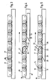
- the more detailed design of the freewheel conveying elements is shown in FIG. 2 to 5 can be seen. They have chain units 14, which form an endless conveyor chain that rotates on a mounting rail.
- 8 denotes a mounting rail, which is arranged directly on the ceiling or on an intermediate bracket with the aid of C-shaped suspension members 9 arranged at a distance from one another.
- the support rail 8 has an upper running surface 10 and a lower surface 11, a box-shaped guide channel being fastened to the latter.
- Each chain unit 14 consists of two rollers 15 which are articulated to one another by means of two brackets 16.
- the chain units 14 are connected to one another in an articulated manner with the aid of support elements 17.
- the support elements are U-shaped in cross section with legs directed downward and are so long that they abut one another with their end faces 18 when the chain is stretched. In this way, the surfaces 19 of the support elements form a continuous support rail for the carriages.
- Each driver 20 has two legs 21 and 22 arranged essentially perpendicular to one another and is pivotally attached to the common connecting point 23 of the two legs 21 and 22 on the axis of the leading roller 15, which belongs to the chain unit 14, which is used to arrange the driver was selected.
- the drivers 20 are designed so that in the rest position shown in FIG. 4, one leg, namely the leg 22, is directed downward and extends downward beyond the contact surface 10 of the rail 8, while the other leg 21 extends approximately horizontally namely below the contact surface 10 of the rail 8.
- laterally rail-shaped actuators 24 which have a wedge-shaped tapered surface 25 in the direction of travel (arrow direction P) and an adjoining surface, the latter lying somewhat below the tread 10 and protruding laterally with respect to the mounting rail 8.
- the leg 22 of the carrier 20 when moving the chain formed from the chain units 14, will run onto the wedge-shaped beveled bearing surface 25 of the actuating member 24, so that the carrier 20 executes a clockwise pivoting motion and that 5 apparent position will occupy.
- This position is inevitably maintained along the entire length of the rail-shaped actuating element 24, since this rail-shaped actuating element 24 prevents the driver 20 from pivoting back into the rest position.
- the actuator 24 can interrupt forced conveyance by means of specially arranged notches. This is useful if the carriage 2 has to be stopped briefly by a stop.
- the aforementioned endless chain formed from the chain units 14 and support elements 17 runs over reversing gearwheels, not shown, the upper strand of the chain being guided freely on the upper running surface 10 of the running rail and the lower strand in the box-shaped channel 12, as is shown in FIG 2 emerges.
- the dimension of the hollow body 2 adapted to the carriage 2 has a high moment of inertia and resistance. Its self-supporting capacity allows wide suspension points. Foreign-induced collisions could never derail the carriage 2. 2 also shows a roller 27 of a carriage 2 (FIG. 2). All of the alternative tracks 6 shown in FIG.
- the straight line sections of the alternative tracks 6 and those of the collective tracks 13 are described with the Provide free-running conveyor systems.
- the carriages 2 are non-positively conveyed on these initial sections of the areas equipped with free-wheeling conveying systems, as will be described below. It is still important that each initial section corresponds essentially to the length of a carriage 2.
- this track 13 is equipped with the freewheel conveying elements described, a rail-shaped actuating element 24 being provided at the start section 13a, which activates a driver 20 of the rotating conveyor chain consisting of chain units 14 and support elements 17, so that the same by 90 ° in Is pivoted clockwise and with its leg 21 gets into the carriageway of the carriage, which is thus non-positively and inevitably transported on with the conveyor chain, so that the carriage completely, ie with both the front roller and the rear roller leaves the transition point 28 and with conveyor chain formed by the chain units 14 is advanced.
- the conveyor chain acts as a support member which rolls on the running surface 10 of the support rail 8.
- the length of the actuator 24 is limited to this distance, so that the forced locking of the driver 20 then stops and this returns to the rest position, in which the leg 21 assumes the horizontal position again and no longer acts as a driver.
- the carriage 2 is located on the collecting track 13 and is carried by the conveyor chain arranged on this track, the rollers of the carriage 2 being stationary. Furthermore, the carriage is directed in a similar manner as described to one of the alternative tracks 6 where it is stopped by an end stop 29. In its operative position, the end stop protrudes into the movement path of the carriage 2 and can be brought from this active position into an inactive position, in which the carriage 2 is not hindered. If a carriage 2 is stopped by the end stop 29, the movement of the conveyor chain is not affected by this, since when the conveyor carriage is stopped, the idler rollers 27 which have been stationary until then are activated and begin to roll. If further carriages 2 arrive, they run onto the already standing carriages, are stopped and remain in the ready position until another processing station becomes free.
- the double track designated 30 in FIG. 1 permits very space-saving storage of transport carriages 31, in that they are guided on different tracks with the front roller and with the rear roller. The distance between the two tracks must be adjusted accordingly to the center distance of the carriages.
- the conveyor system described is very simple, has no complicated control elements and can therefore be operated reliably and very effectively.
Landscapes
- Engineering & Computer Science (AREA)
- Mechanical Engineering (AREA)
- Intermediate Stations On Conveyors (AREA)
Applications Claiming Priority (2)
| Application Number | Priority Date | Filing Date | Title |
|---|---|---|---|
| DE3939288 | 1989-11-28 | ||
| DE19893939288 DE3939288A1 (de) | 1989-11-28 | 1989-11-28 | Foerderanlage |
Publications (1)
| Publication Number | Publication Date |
|---|---|
| EP0430865A1 true EP0430865A1 (fr) | 1991-06-05 |
Family
ID=6394336
Family Applications (1)
| Application Number | Title | Priority Date | Filing Date |
|---|---|---|---|
| EP90810788A Withdrawn EP0430865A1 (fr) | 1989-11-28 | 1990-10-16 | Installation de transport |
Country Status (2)
| Country | Link |
|---|---|
| EP (1) | EP0430865A1 (fr) |
| DE (1) | DE3939288A1 (fr) |
Citations (4)
| Publication number | Priority date | Publication date | Assignee | Title |
|---|---|---|---|---|
| GB101602A (en) * | 1916-05-15 | 1916-10-05 | Ransome & Company Ltd A | Improvements in Lumber Jointing Machines. |
| FR2311734A1 (fr) * | 1975-05-20 | 1976-12-17 | Mueller Karl Automation | Systeme de transfert pour le transport horizontal en boucle fermee de supports destines a la manutention d'objets |
| FR2448975A1 (fr) * | 1979-02-16 | 1980-09-12 | Martin Sa | Dispositif d'entrainement de plaques |
| GB2152463A (en) * | 1984-01-13 | 1985-08-07 | Stockrail Services Ltd | Powered overhead conveyor systems |
Family Cites Families (6)
| Publication number | Priority date | Publication date | Assignee | Title |
|---|---|---|---|---|
| DE7105714U (de) * | 1971-05-13 | Ruberg & Renner Gmbh | Transportglied fur Forderketten | |
| DD72748A (fr) * | ||||
| CH349213A (de) * | 1955-08-30 | 1960-09-30 | Reifenhaeser Anton | Verfahren und Vorrichtung zum kontinuierlichen Transportieren von Profilsträngen, insbesondere Abziehen von einer Produktionsmaschine |
| GB964023A (en) * | 1961-07-12 | 1964-07-15 | Sovex Ltd | Improvements relating to underfloor towing-chain conveyers |
| JPS5273485A (en) * | 1975-12-11 | 1977-06-20 | Murata Mach Ltd | Apparatus for forwarding, collecting and delivering trolley for transp orting goods |
| DE3317403C1 (de) * | 1983-05-13 | 1984-10-11 | Dürkoppwerke GmbH, 4800 Bielefeld | Stau-Haengefoerderer mit einer in der Horizontalebene umlaufenden,endlosen Trag- und Fuehrungsschiene |
-
1989
- 1989-11-28 DE DE19893939288 patent/DE3939288A1/de not_active Withdrawn
-
1990
- 1990-10-16 EP EP90810788A patent/EP0430865A1/fr not_active Withdrawn
Patent Citations (4)
| Publication number | Priority date | Publication date | Assignee | Title |
|---|---|---|---|---|
| GB101602A (en) * | 1916-05-15 | 1916-10-05 | Ransome & Company Ltd A | Improvements in Lumber Jointing Machines. |
| FR2311734A1 (fr) * | 1975-05-20 | 1976-12-17 | Mueller Karl Automation | Systeme de transfert pour le transport horizontal en boucle fermee de supports destines a la manutention d'objets |
| FR2448975A1 (fr) * | 1979-02-16 | 1980-09-12 | Martin Sa | Dispositif d'entrainement de plaques |
| GB2152463A (en) * | 1984-01-13 | 1985-08-07 | Stockrail Services Ltd | Powered overhead conveyor systems |
Also Published As
| Publication number | Publication date |
|---|---|
| DE3939288A1 (de) | 1991-06-20 |
Similar Documents
| Publication | Publication Date | Title |
|---|---|---|
| EP2784009B1 (fr) | Procédé et dispositif de transfert de marchandises au détail au niveau d'une installation de transport | |
| DE102007017511C5 (de) | Antriebseinheit, Antriebssystem und Förderanlage für Skids zum Tragen eines Gegenstandes | |
| EP0458021B1 (fr) | Entrepôt avec rayonnages pour matériel recueilli dans des cassettes autoporteuses | |
| DE4203799C2 (de) | Anlage zum Verteilen von Stückgütern | |
| DE69904806T2 (de) | Pufferspeicher mit variabler kapazität für stabförmige artikel | |
| EP1189825A1 (fr) | Dispositif de transport et/ou de stockage pour marchandises en colis | |
| CH707798A1 (de) | Schienengeführtes Fördermittel und Förderanlage mit derartigen Fördermitteln. | |
| DE3109174A1 (de) | Ausschleusvorrichtung fuer eine foerderbahn | |
| DE102011100825B4 (de) | Spindelförderer und Anlage zum Behandeln von Werkstücken mit einem solchen | |
| EP1283809B1 (fr) | Dispositif de transport d'un rouleau | |
| DE2032776C3 (de) | Schleppkettenkreisförderanlage | |
| DE2303425C3 (de) | Hängebahnanlage mit Transporteinheiten | |
| EP0829578A2 (fr) | Aiguillage pour installation monorail de manutention | |
| DE112014003903B4 (de) | Transportvorrichtung | |
| DE4218336C2 (de) | Vorrichtung zum Sammeln und geordneten Bündeln von langgestrecktem Walzgut | |
| EP0438379A1 (fr) | Dispositif suspendu de convoyage avec une quantité de voies de stockage ou de transport disposées en lignes parallèles | |
| EP1057758A1 (fr) | Convoyeur vertical selon le principe paternoster | |
| EP0430865A1 (fr) | Installation de transport | |
| EP0431141A1 (fr) | Chariot d'entreposage et de transfert de porteurs de marchandises. | |
| EP0683118B1 (fr) | Dispositif de stockage d'objets, en particulier des récipients de stockage | |
| DE19816960C2 (de) | Fördergut-Bremseinrichtung | |
| DE10044612A1 (de) | Kippstation für Stückgutförderer | |
| DE3921357C1 (fr) | ||
| DE19540177C2 (de) | Fördersystem | |
| DE4430562A1 (de) | Vorrichtung und Verfahren zum Fördern von Stückgut auf parallel und drehbar gelagerten Rollen |
Legal Events
| Date | Code | Title | Description |
|---|---|---|---|
| PUAI | Public reference made under article 153(3) epc to a published international application that has entered the european phase |
Free format text: ORIGINAL CODE: 0009012 |
|
| AK | Designated contracting states |
Kind code of ref document: A1 Designated state(s): AT BE CH DE DK ES FR GB GR IT LI LU NL SE |
|
| STAA | Information on the status of an ep patent application or granted ep patent |
Free format text: STATUS: THE APPLICATION IS DEEMED TO BE WITHDRAWN |
|
| 18D | Application deemed to be withdrawn |
Effective date: 19911206 |