EP0430780A1 - Dispositif de transport comportant au moins un élément convoyeur se déplaçant selon un circuit déterminé - Google Patents
Dispositif de transport comportant au moins un élément convoyeur se déplaçant selon un circuit déterminé Download PDFInfo
- Publication number
- EP0430780A1 EP0430780A1 EP90403322A EP90403322A EP0430780A1 EP 0430780 A1 EP0430780 A1 EP 0430780A1 EP 90403322 A EP90403322 A EP 90403322A EP 90403322 A EP90403322 A EP 90403322A EP 0430780 A1 EP0430780 A1 EP 0430780A1
- Authority
- EP
- European Patent Office
- Prior art keywords
- chain
- guide rail
- conveyor element
- primary guide
- sheath
- Prior art date
- Legal status (The legal status is an assumption and is not a legal conclusion. Google has not performed a legal analysis and makes no representation as to the accuracy of the status listed.)
- Withdrawn
Links
- 238000005096 rolling process Methods 0.000 claims description 4
- 239000000463 material Substances 0.000 claims description 3
- 229920003023 plastic Polymers 0.000 claims description 3
- 239000004033 plastic Substances 0.000 claims description 3
- 230000000284 resting effect Effects 0.000 claims 1
- 239000002184 metal Substances 0.000 description 3
- 239000000725 suspension Substances 0.000 description 2
- 239000004698 Polyethylene Substances 0.000 description 1
- 238000009434 installation Methods 0.000 description 1
- -1 polyethylene Polymers 0.000 description 1
- 229920000573 polyethylene Polymers 0.000 description 1
- 125000006850 spacer group Chemical group 0.000 description 1
- 238000004804 winding Methods 0.000 description 1
Images

Classifications
-
- B—PERFORMING OPERATIONS; TRANSPORTING
- B61—RAILWAYS
- B61B—RAILWAY SYSTEMS; EQUIPMENT THEREFOR NOT OTHERWISE PROVIDED FOR
- B61B3/00—Elevated railway systems with suspended vehicles
-
- B—PERFORMING OPERATIONS; TRANSPORTING
- B65—CONVEYING; PACKING; STORING; HANDLING THIN OR FILAMENTARY MATERIAL
- B65G—TRANSPORT OR STORAGE DEVICES, e.g. CONVEYORS FOR LOADING OR TIPPING, SHOP CONVEYOR SYSTEMS OR PNEUMATIC TUBE CONVEYORS
- B65G19/00—Conveyors comprising an impeller or a series of impellers carried by an endless traction element and arranged to move articles or materials over a supporting surface or underlying material, e.g. endless scraper conveyors
- B65G19/02—Conveyors comprising an impeller or a series of impellers carried by an endless traction element and arranged to move articles or materials over a supporting surface or underlying material, e.g. endless scraper conveyors for articles, e.g. for containers
- B65G19/025—Conveyors comprising an impeller or a series of impellers carried by an endless traction element and arranged to move articles or materials over a supporting surface or underlying material, e.g. endless scraper conveyors for articles, e.g. for containers for suspended articles
-
- E—FIXED CONSTRUCTIONS
- E01—CONSTRUCTION OF ROADS, RAILWAYS, OR BRIDGES
- E01B—PERMANENT WAY; PERMANENT-WAY TOOLS; MACHINES FOR MAKING RAILWAYS OF ALL KINDS
- E01B25/00—Tracks for special kinds of railways
- E01B25/22—Tracks for railways with the vehicle suspended from rigid supporting rails
- E01B25/24—Supporting rails; Auxiliary balancing rails; Supports or connections for rails
Definitions
- the present invention relates to a transport device comprising at least one conveyor element sse moving along a determined circuit.
- Such transport devices have already been known for a long time and used, in particular, on industrial parks to move, at a certain height above the ground, from one workstation to another, products treated in a chain.
- These devices conventionally include a primary guide rail serving as a support, in which conveyor elements slide on which products to be transported are hung, this guide rail being associated with a drive chain arranged next to said rail and cooperating with said elements. conveyors, to drive them in movement along said guide rail, this drive chain being driven linearly by means of motor means.
- An object of the present invention is to overcome these drawbacks by proposing a device in which the drive chain and the conveyor element are integral with each other in movement, so that a stop of the chain causes instantly also stop the conveyor elements. It is clear that such a solution effectively allows better precision in controlling the movement of the elements to be transported.
- the invention also provides a device in which the cooperation between the drive chain and the conveyor element is obtained by driving a toothing which is provided with said conveyor element with links of said chain, so that the engagement of a conveyor element is done by simple presentation of the latter at the level of the conveyor chain, the toothing of said element adjusting itself on the links of the chain.
- Another object of the present invention is to provide a transport device of the aforementioned type which can be easily mounted and adapted for all types of installations. To this end, it proposes, in particular, to arrange the guide rail and the drive chain in the same sheath, which can easily be hung, for example, on a ceiling.
- the present invention therefore relates to a transport device comprising at least one conveyor element moving along a determined circuit, by sliding of one of its parts in a primary guide rail, said conveyor element being driven in its movement by means of at least one chain comprising a return part and a drive part arranged, at least partially, along and next to said guide rail, said chain being actuated in a closed circuit by motor means, characterized in that said chain is a link chain, the conveyor element being provided with a toothing, which meshes with the links of said chain and secures, in movement, said chain and said conveyor element.
- the drive part of a chain is disposed, at least partially, in a secondary drive guide rail.
- the return part of a chain can be arranged, at least partially, in a secondary return guide rail.
- the device may, in particular, comprise a sheath internally comprising a primary guide rail juxtaposed with a secondary drive guide rail and a secondary return guide rail, said primary guide rail and said secondary drive guide rail being connected in their length by a linear recess in which the part of the conveyor element which moves with the links of the chain moves.
- the secondary drive guide rail is included between the primary guide rail and the secondary return guide rail.
- the sheath may comprise, along its length, a recess intended for the passage of cables, in particular electrical or pneumatic.
- the sheath can be a profile provided linearly with recesses which serve as primary guide rail and secondary guide rails.
- the sheath can be produced then, at least partially, of a plastic material.
- the sheath is suspended in points on a support by means of threaded rods provided with screws and nuts, the edges of which cooperate with fixing flanges integral with said sheath.
- the sheath fixing flanges can be two cylindrical sectors arranged opposite, a screw passing through these two sectors and cooperating with two nuts whose edges are supported respectively on each of said sectors.
- each link of a chain is defined by two parallel lateral blanks connected respectively to the two blanks of an adjacent link by an axis carrying three coaxial cylinders which can pivot around said axis, one of the cylinders being between the two blanks and the other two being arranged outside the two blanks, on either side of the chain, the cylinders arranged between the blanks of the links meshing with the teeth of a conveyor element, the lateral cylinders rolling on the wall of a secondary guide rail in which they are arranged.
- a conveyor element can be supported by rollers rolling on a wall of the primary guide rail.
- the device can also include several chains, the drive parts of which are arranged in the extension of one another, said chains being able to be actuated at different speeds.
- the device may also include at least a portion of secondary guide rail which is not associated with any chain.
- the primary guide rail comprises at least one opening for engaging conveyor elements.
- a conveyor element may comprise a flat thin head carrying the toothing of said conveyor element and having a cross section, in the middle plane of said toothing, substantially rounded.
- the teeth of a conveyor element can have three teeth.
- the device comprises two primary guide rails substantially juxtaposed and associated at one end common to a pinion on which drives a chain commonly associated with the two primary guide rails, said pinion itself being tangentially surrounded by a guide rail. connecting one to the other said primary guide rails and in which the (or) element (s) conveyor (s) are intended to slide with engagement of their teeth with the chain.
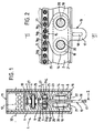
- a transport device essentially comprises an elongated main sheath 1, having inside its three recesses passing through it over its entire length and arranged one above the other, these three recesses serving , one, referenced by 2 of primary guide rail, the other two, referenced by 3 and 4, secondary rails intended to contain a link chain 5 closed on itself to form a loop and carried, at both ends of said sheath, by wheels, said chain 5 being driven in its movement by a motor means, such as an electric motor.
- the sheath 1 comprises two lateral cheeks 6 and 7 profiled in a plastic material, which can be polyethylene, these two cheeks 6 and 7 by their internal profile delimiting between them the primary guide rail 2 and the secondary rails 3 and 4.
- These two cheeks 6 and 7 are arranged between two sheet metal strips 8 bordering their outer walls and holding them one on the other by means of bolts 32 distributed regularly from the sheath 1, their spacing being ensured by means of spacers 9 and 10 also arranged regularly over the entire length of the sheath 1, some 9 between the two secondary rails, the others referenced by 10 beyond the secondary rail furthest from the primary guide rail 2.
- the sheath 1 comprises, over its entire length, a square tube 11, which is inserted by force between the two strips of sheet metal 8 and in which electrical cables or conduits can be passed tires 12 used for the operation of the device and, by example, to the power supply to the motor setting the chain in motion 5.
- a conveyor element 13 comprises a head 14, which is a plate of small thickness, said thickness being slightly less than the minimum spacing between the two cheeks 6 and 7 at the level primary guide rail 2.
- This head 14 has a partially elliptical, partially rectilinear outline; its elliptical border cheek has a toothing 15 symmetrical with respect to the minor axis of the elliptical zone of the contour and comprising three teeth, 16 a , 16 b , and 16 c .
- the central tooth 16 b essentially serves to secure the connection between the conveyor element 13 and the drive chain 5 during the movement of said conveyor element 13 in its primary guide rail 2.
- the lateral teeth 16 a and 16 c serve, essentially ensuring respectively the initial engagement and the final disengagement of the conveyor element 13 with the chain 5.
- the edge of the head 14 in its thickness is rectilinear and parallel to the major axis of the elliptical zone of the contour of said head 14.
- the head 14 is extended, in this rectilinear zone by an element of hooking 17 substantially rectangular and the mean longitudinal line of which is situated on the minor axis of the elliptical zone of the contour, its end opposite the edge of the head 14 being delimited by a semicircle.
- This attachment element 17 is crossed, along its average longitudinal line, by an oblong hole 18, intended to allow the attachment of elements to be transported, for example pliers or the like.
- Each of the two faces of the head 14 is provided with two identical rollers 19 and 20, these rollers being pivotally mounted along perpendicular axes in the plane of the faces of the head 14, symmetrically, on each side with respect to the minor axis of the elliptical zone of said head 14, the diameter of these rollers 19 and 20 being such that the projection of said rollers on the faces of head 14 is completely included within the outline of said head.
- rollers 19 and 20 are intended to come to rest and to roll on flanges 21 and 22, which respectively terminate the cheeks 6 and 7, at their ends opposite to the tube 11, said flanges 21 and 22 constituting the bottom of the guide rail primary 2 and being in a plane substantially perpendicular to the plane of the heads 14, when these are in place in the primary guide rail 2.
- the primary guide rail 2 has a substantially hexagonal cross section; it is extended at its end opposite to said flanges 21 and 22, by a recess 23 produced over the entire length of the sheath 1, this recess 23 allowing communication between the primary guide rail 2 and the secondary drive guide rail 3 , which is juxtaposed to it and having a thickness substantially identical to the distance which separates the flanges 21 and 22; the recess 23 is, moreover, centered on the median longitudinal plane of the sheath 1. In this recess 23 slides the part of the head 14 located between the teeth 15 and the rollers 19 and 20, the teeth 15 being found at the level of chain 5 and meshing with the links of said chain.
- the chain 5 comprises series of three coaxial cylinders, 24 a , 24 b , 24 c , said series being linked in pairs by articulation blanks to constitute the links of the chain, the side cylinders 24 a and 24 c roll on the bottom of the secondary guide rail 3, said secondary rail 3 being defined by a substantially parallelepiped recess;
- median 24 b cylinders are spaced from each other and are intended to mesh with the toothing 15 of the head 14.
- Each link of a channel 5 is defined by two parallel lateral flanks 27, connected respectively to two blanks of a link adjacent by the axis of a series of three cylinders 24 a , 24 b , 24 c , said blanks 27 being arranged on each side of the middle cylinder 24 b , perpendicular to its axis, the lateral cylinders 24 a and 24 b being on the outside of the links.
- Each of the two secondary rails 3 and 4 is provided with recesses 25 and 26 respectively, in which are intended to pass articulation blanks 27 of the chain 5.
- the walls of the tube 11, which are parallel to the sheet metal strips 8, are raised to the right of the attachment brackets of the device.
- the top core of the tube 11 is removed between the two raised side walls 26.
- the raised walls 26 have a right-angled flange 26 has along their upper edges.
- a semicircular element 28 a , 28 b has been placed , these elements being welded at their ends to said angle returns 26 a .
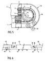
- FIG. 5 shows a device referenced by 33 as a whole, making it possible to obtain a rapid and space-saving reversal of the conveyor elements 13.
- a reversal device 33 can, for example, be used to return the conveyor elements from the end of the chain to the beginning.
- This device 33 consists essentially of a pinion 34 comprising two identical toothed wheels 35, mounted on the same axis opposite one another and whose teeth are intended to cooperate respectively with the side cylinders 24 a and 24 c of the chain 5, these two wheels 35 being separated from each other by a spacing in which is housed the internal part of the chain 5, namely the cylinders 24b and the sides 27.
- This pinion 34 is arranged at the ends of two sheaths 1 juxtaposed one with the other, their primary guide rail 2 being arranged so that the teeth 15 of the conveyor elements are present substantially tangentially with respect to the wheels of said pinion 34.
- the pinion 34 is surrounded, in the extension of each of said guide rails 2, by a guide rail 36 intended to conduct the conveyor elements 13 from one sheath 1 to the other, said sheaths 1 being associated with the same passing chain 5 from one secondary guide rail 3 to the other after winding on the pinion 34, the secondary guide rails 4 not being provided with any chain 5.
- FIG. 6 it is possible, using a transport device of the type which has just been described, to produce a transport network comprising several sheath portions 1 in the extension of one of the others, associated with distinct chains, which makes it possible to produce a network comprising portions on which the conveyor elements are driven at different speeds, certain portions of the network possibly even being associated with no transport chain, so as to achieve, for example, control stations for the elements to be transported.
- the sheaths 1 proposed by the invention have, in particular, the advantage of being able to be easily cut out at their secondary guide rails 3 and 4, so that it is possible to produce, in the length of said sheath, recesses 37 at the level of said secondary rails 3 and 4, in which rollers 38 and drive wheels 39 are placed, over which the chains 5 pass.
Landscapes
- Engineering & Computer Science (AREA)
- Mechanical Engineering (AREA)
- Transportation (AREA)
- Architecture (AREA)
- Civil Engineering (AREA)
- Structural Engineering (AREA)
- Framework For Endless Conveyors (AREA)
Applications Claiming Priority (2)
| Application Number | Priority Date | Filing Date | Title |
|---|---|---|---|
| FR8915403 | 1989-11-23 | ||
| FR8915403A FR2654709A1 (enExample) | 1989-11-23 | 1989-11-23 |
Publications (1)
| Publication Number | Publication Date |
|---|---|
| EP0430780A1 true EP0430780A1 (fr) | 1991-06-05 |
Family
ID=9387706
Family Applications (1)
| Application Number | Title | Priority Date | Filing Date |
|---|---|---|---|
| EP90403322A Withdrawn EP0430780A1 (fr) | 1989-11-23 | 1990-11-23 | Dispositif de transport comportant au moins un élément convoyeur se déplaçant selon un circuit déterminé |
Country Status (2)
| Country | Link |
|---|---|
| EP (1) | EP0430780A1 (enExample) |
| FR (1) | FR2654709A1 (enExample) |
Cited By (1)
| Publication number | Priority date | Publication date | Assignee | Title |
|---|---|---|---|---|
| EP4074630A1 (de) * | 2021-04-16 | 2022-10-19 | BEUMER Group GmbH & Co. KG | Transferschienenprofil und anordnung mit einem transportelement |
Citations (6)
| Publication number | Priority date | Publication date | Assignee | Title |
|---|---|---|---|---|
| BE634630A (enExample) * | 1962-07-10 | |||
| US1972931A (en) * | 1931-03-10 | 1934-09-11 | Charles S Haddlesay | Track for monorail conveyer systems |
| FR1131953A (fr) * | 1954-05-08 | 1957-03-04 | Demag Zug Gmbh | Dispositif pour la fixation des rails de voies de roulement suspendues |
| DE1912044U (de) * | 1964-09-26 | 1965-03-18 | Deyle Elektrobau K G | Laufschiene fuer rollen einer elektrohaengebahn. |
| DE3110833A1 (de) * | 1981-03-19 | 1982-10-14 | Gustav Georg Veith GmbH & Co KG, 8201 Frasdorf | Foerdereinrichtung |
| EP0164109A1 (de) * | 1984-06-05 | 1985-12-11 | Franz Gärtner | Selbsttätige Transportvorrichtung für eine Hängefördervorrichtung |
-
1989
- 1989-11-23 FR FR8915403A patent/FR2654709A1/fr active Pending
-
1990
- 1990-11-23 EP EP90403322A patent/EP0430780A1/fr not_active Withdrawn
Patent Citations (6)
| Publication number | Priority date | Publication date | Assignee | Title |
|---|---|---|---|---|
| US1972931A (en) * | 1931-03-10 | 1934-09-11 | Charles S Haddlesay | Track for monorail conveyer systems |
| FR1131953A (fr) * | 1954-05-08 | 1957-03-04 | Demag Zug Gmbh | Dispositif pour la fixation des rails de voies de roulement suspendues |
| BE634630A (enExample) * | 1962-07-10 | |||
| DE1912044U (de) * | 1964-09-26 | 1965-03-18 | Deyle Elektrobau K G | Laufschiene fuer rollen einer elektrohaengebahn. |
| DE3110833A1 (de) * | 1981-03-19 | 1982-10-14 | Gustav Georg Veith GmbH & Co KG, 8201 Frasdorf | Foerdereinrichtung |
| EP0164109A1 (de) * | 1984-06-05 | 1985-12-11 | Franz Gärtner | Selbsttätige Transportvorrichtung für eine Hängefördervorrichtung |
Cited By (1)
| Publication number | Priority date | Publication date | Assignee | Title |
|---|---|---|---|---|
| EP4074630A1 (de) * | 2021-04-16 | 2022-10-19 | BEUMER Group GmbH & Co. KG | Transferschienenprofil und anordnung mit einem transportelement |
Also Published As
| Publication number | Publication date |
|---|---|
| FR2654709A1 (enExample) | 1991-05-24 |
Similar Documents
| Publication | Publication Date | Title |
|---|---|---|
| EP2632827B1 (fr) | Unité régulatrice versatile pour flux de récipients | |
| FR2714008A3 (fr) | Mécanisme pour déplacer des lits. | |
| CH687324A5 (fr) | Cadre de support momentané d'un élément en plaque horizontal au sein d'une machine. | |
| FR2684396A1 (fr) | Vehicule de pose automatique d'une voie par un vehicule se deplacant sur cette voie, et voie concue pour etre installee par un tel vehicule. | |
| EP0576353A1 (fr) | Elément de transporteur à vitesse variable en particulier pour trottoirs roulants accélérés | |
| EP0326463B1 (fr) | Appareil de manutention destiné à déplacer, suivant une direction longitudinale sensiblement horizontale, des charges unitaires reposant sur des organes de roulement | |
| EP0000297A1 (fr) | Lève-glace, notamment pour véhicules automobiles | |
| EP0430780A1 (fr) | Dispositif de transport comportant au moins un élément convoyeur se déplaçant selon un circuit déterminé | |
| EP0007264B1 (fr) | Chaîne à un seul sens de courbure et application à une main courante | |
| WO2007015000A1 (fr) | Procede de groupage de caisses sur un convoyeur et dispositif pour sa mise en œuvre | |
| CH619656A5 (en) | Handling device comprising an overhead track | |
| FR2668758A1 (fr) | Dispositif pour transferer des palettes entre deux convoyeurs orthogonaux. | |
| EP0282427B1 (fr) | Dipositif d'assemblage des différentes pièces d'un élément de ferrure | |
| EP1054129A1 (fr) | Dispositif d'ouverture et de fermeture motorisée d'un vantail de portail ou analogue | |
| EP0220967B1 (fr) | Convoyeur de récipients | |
| EP0876946B1 (fr) | Dispositif opérateur de porte, porte pourvue de ce dispositif et véhicule ferroviaire équipé d'au moins un tel dispositif et/ou porte | |
| FR2784264A1 (fr) | Dispositif de raclage a trajectoire courbe, pour l'elimination des dechets | |
| CH648259A5 (fr) | Dispositif de conditionnement d'objets. | |
| FR2634471A1 (fr) | Dispositif pour le positionnement et l'arret d'objets deplaces sur un transporteur | |
| FR2474872A1 (fr) | Dispositif d'attache pour ceintures de securite | |
| EP1424148B1 (fr) | Installation de presse comportant une table de support de bande | |
| FR2711892A1 (fr) | Dispositif d'abreuvement pour une installation de gavage de volailles. | |
| EP0629565A1 (fr) | Table télescopique à rouleaux de manutention | |
| FR2822025A1 (fr) | Dispositif de faconnage de patons de pain ou analogues | |
| FR2538835A1 (fr) | Enceinte telle que garage, a porte basculante manoeuvrant un portillon coulissant |
Legal Events
| Date | Code | Title | Description |
|---|---|---|---|
| PUAI | Public reference made under article 153(3) epc to a published international application that has entered the european phase |
Free format text: ORIGINAL CODE: 0009012 |
|
| AK | Designated contracting states |
Kind code of ref document: A1 Designated state(s): AT BE CH DE DK ES GB IT LI LU NL SE |
|
| 17P | Request for examination filed |
Effective date: 19911017 |
|
| 17Q | First examination report despatched |
Effective date: 19930312 |
|
| STAA | Information on the status of an ep patent application or granted ep patent |
Free format text: STATUS: THE APPLICATION IS DEEMED TO BE WITHDRAWN |
|
| 18D | Application deemed to be withdrawn |
Effective date: 19940913 |