EP0429939B1 - Stellungssensor für Landeklappenhebel bei Flugzeugen - Google Patents
Stellungssensor für Landeklappenhebel bei Flugzeugen Download PDFInfo
- Publication number
- EP0429939B1 EP0429939B1 EP90121608A EP90121608A EP0429939B1 EP 0429939 B1 EP0429939 B1 EP 0429939B1 EP 90121608 A EP90121608 A EP 90121608A EP 90121608 A EP90121608 A EP 90121608A EP 0429939 B1 EP0429939 B1 EP 0429939B1
- Authority
- EP
- European Patent Office
- Prior art keywords
- printed circuit
- circuit boards
- code disc
- landing flap
- housing
- Prior art date
- Legal status (The legal status is an assumption and is not a legal conclusion. Google has not performed a legal analysis and makes no representation as to the accuracy of the status listed.)
- Expired - Lifetime
Links
- 230000003287 optical effect Effects 0.000 claims description 13
- 230000004888 barrier function Effects 0.000 claims description 3
- 238000010276 construction Methods 0.000 description 3
- 230000005540 biological transmission Effects 0.000 description 1
- 230000008030 elimination Effects 0.000 description 1
- 238000003379 elimination reaction Methods 0.000 description 1
- 230000005693 optoelectronics Effects 0.000 description 1
- 210000003813 thumb Anatomy 0.000 description 1
Images
Classifications
-
- G—PHYSICS
- G01—MEASURING; TESTING
- G01D—MEASURING NOT SPECIALLY ADAPTED FOR A SPECIFIC VARIABLE; ARRANGEMENTS FOR MEASURING TWO OR MORE VARIABLES NOT COVERED IN A SINGLE OTHER SUBCLASS; TARIFF METERING APPARATUS; MEASURING OR TESTING NOT OTHERWISE PROVIDED FOR
- G01D5/00—Mechanical means for transferring the output of a sensing member; Means for converting the output of a sensing member to another variable where the form or nature of the sensing member does not constrain the means for converting; Transducers not specially adapted for a specific variable
- G01D5/26—Mechanical means for transferring the output of a sensing member; Means for converting the output of a sensing member to another variable where the form or nature of the sensing member does not constrain the means for converting; Transducers not specially adapted for a specific variable characterised by optical transfer means, i.e. using infrared, visible, or ultraviolet light
- G01D5/32—Mechanical means for transferring the output of a sensing member; Means for converting the output of a sensing member to another variable where the form or nature of the sensing member does not constrain the means for converting; Transducers not specially adapted for a specific variable characterised by optical transfer means, i.e. using infrared, visible, or ultraviolet light with attenuation or whole or partial obturation of beams of light
- G01D5/34—Mechanical means for transferring the output of a sensing member; Means for converting the output of a sensing member to another variable where the form or nature of the sensing member does not constrain the means for converting; Transducers not specially adapted for a specific variable characterised by optical transfer means, i.e. using infrared, visible, or ultraviolet light with attenuation or whole or partial obturation of beams of light the beams of light being detected by photocells
- G01D5/347—Mechanical means for transferring the output of a sensing member; Means for converting the output of a sensing member to another variable where the form or nature of the sensing member does not constrain the means for converting; Transducers not specially adapted for a specific variable characterised by optical transfer means, i.e. using infrared, visible, or ultraviolet light with attenuation or whole or partial obturation of beams of light the beams of light being detected by photocells using displacement encoding scales
- G01D5/3473—Circular or rotary encoders
Definitions
- the invention relates to a flap control in aircraft with a position sensor for flap levers.
- DE-U-8 416 558 generally shows a position measuring device with an optoelectronic coding disk.
- flaps and “flaps” are provided on the wings of aircraft. These are moved to different angular positions during takeoff and landing to increase lift.
- the flaps are operated hydraulically.
- the hydraulics are controlled electronically.
- the electronics are controlled by a “flap lever” in the cockpit.
- flap levers In known flap levers, a plurality of mechanical switches in certain positions, which can be actuated by the flap lever and detect the lever position, serve as position sensors.
- the invention has for its object to build a flap control on aircraft with a position sensor for flap lever simple, inexpensive and space-saving.
- this object is achieved in that a coding disk is connected to the flap lever via an input shaft rotatably mounted in the housing of the position sensor, the position of which can be sensed by an optical sensor with such a resolution that the angle entered on the flap lever can be detected directly.
- the position sensor is less expensive due to the elimination of expensive, electromechanical switches.
- the transmission for increasing the angle of rotation is omitted, since the resolution of the system with the coding disk and optical sensor is so great that the angles entered on the flap lever can be detected directly.
- This construction gives the possibility that the coding disk and optical sensor are provided multiple times.
- annular disk-shaped printed circuit boards are also held in the housing of the position sensor in parallel to one another and coaxially with the input shaft.
- Optical sensors are located on the circuit boards.
- a coding disk is connected to the input shaft in a rotationally fixed manner, protrudes between the printed circuit boards and interacts with the optical sensors.
- the optical sensors can be light barriers, of which a transmitter is arranged on one and a receiver on the other circuit board.
- an aperture plate can be arranged in the housing and parallel to the printed circuit boards and the coding disk between each printed circuit board and the coding disk.
- a hollow cylindrical bearing bracket is attached to an end wall of the housing and protrudes into the interior of the housing.
- the input shaft is mounted in the bearing bracket by means of at least two roller bearings.
- Two pairs of parallel annular printed circuit boards are held in the housing.
- the circuit boards of a pair coaxially surround the bearing bracket.
- a coding disk carrier is connected in a rotationally fixed manner to the input shaft.
- the encoder disk carrier engages around the outside of the bearing carrier with a cup-shaped part and carries an encoder disk protruding between said pair of printed circuit boards.
- the encoder disk carrier further has a second cup-shaped part which is arranged back-to-back with said first cup-shaped part and carries a second coding disk which projects between the second pair of printed circuit boards.
- a flat housing 10 is closed by a cover 12.
- a hollow cylindrical bearing bracket 14 is seated in the lid 12.
- the bearing bracket 14 has at its outer end a flange 16 which is connected to the lid 12 by screws 18 and nuts 20.
- an input shaft 22 is rotatably supported in roller bearings 24 and 26 about an axis 28.
- the input shaft 22 has a spline toothed head 30 which projects through the cover 12. This head can be connected to a flap lever (not shown).
- the bearing bracket 14 projects into the interior of the housing 10 up to approximately the middle.
- the housing 10 has an opening 32 on the side opposite the head 30.
- the opening 32 is covered by a cap 34, which is connected to a flange 36 by screws 38 with the housing 10.
- An end 40 of the input shaft 22 projects into the cap 34.
- the end 40 of the input shaft 22 is provided with spline teeth 42.
- brake discs 44 and 46 are axially movable but non-rotatably guided.
- a friction disk 48 which is provided on both sides with brake pads and is non-rotatably held in the housing 10 in an internal toothing 50 on the inside of the opening 32.
- a nut 54 is seated on a threaded end 52 of the input shaft 22.
- a spring abutment 56 is supported on the nut 54.
- a nut 60 sits on a threaded middle part 58 of the input shaft 22.
- a helical spring 62 surrounds the input shaft 22 and bears on the one hand on the spring abutment 56 and on the other hand on the brake disc 46. In this way, the prestressing of the helical spring 62 presses the brake disk 44 from the left in the figure via the nut 60 to the right against the friction disk 48, while at the same time the brake disk 46 is pressed to the left against the friction disk 48 by the spring.
- This arrangement forms a slip clutch which frictionally holds the input shaft 22 and thus the coding disks 78 and 88 in the respectively assumed position in the event of a breakage of the input shaft 22.
- the circuit boards 64, 66, 68, 70 lie in radial planes with respect to the axis 28. They are therefore parallel to one another and have central openings which are coaxial with the axis 28 and the input shaft 22.
- the circuit boards 64 and 66 of a pair surround the bearing bracket 14. They are therefore arranged axially in the area of the bearing bracket 14.
- the other printed circuit boards 68 and 70 are located to the right of the inner end of the bearing bracket 14.
- a coding disk bracket 72 is connected to the input shaft 22 in a rotationally fixed manner by means of a tongue and groove connection 74.
- the encoder disk carrier 72 engages with a cup-shaped part 70 around the bearing carrier 14 on the outside.
- the pot-shaped part 76 carries on its edge a coding disk 78 which projects between the pair 64, 66 of printed circuit boards.
- Two diaphragm disks 80 and 82 are also held in the housing 10.
- the diaphragm disks 80 and 82 are parallel to one another and to the printed circuit boards 64 and 66.
- a diaphragm disk 80 or 82 is arranged between each of the printed circuit boards 64 or 66 and the coding disk 78.
- the encoder disk carrier 72 has a second cup-shaped part 84 which is arranged back-to-back with the first cup-shaped part 76.
- the second cup-shaped part 84 carries a second coding disk 88.
- the second coding disk 88 projects between the second pair 68, 70 of printed circuit boards. From here in the housing 10 and parallel to the circuit boards 68 and 70 and the coding disk 88, an aperture disk 90 and 92 is arranged fixed to the housing between each circuit board 68 and 70 and the coding disk 88.
- the optical sensors are located on the circuit boards.
- the optical sensors are light barriers, of which a transmitter 94 or 96 is arranged on a circuit board 64 or 68 and a receiver 98 and 100 is arranged on the other circuit board 66 or 70.
- the circuit boards contain other electronic components.
- the output signals of the position sensor are output via a connector plug 102.
Landscapes
- Physics & Mathematics (AREA)
- General Physics & Mathematics (AREA)
- Transmission And Conversion Of Sensor Element Output (AREA)
- Optical Transform (AREA)
Description
- Die Erfinding betrifft eine Landeklappensteuerung bei Flugzeugen mit einem Stellungssensor für Landeklappenhebel.
- Eine Veröffentlichung ""Thumball" Auxiliary Data-Input Device" in NASA Tech Brief NTIS Tech Notes, Juni 1988, Seite 484, beschreibt einen in den Griff eines Steuerknüppels eingebauten Mechanismus mit einer aus der Stirnfläche dieses Griffes vorstehenden Kugel. Die Bewegung der Kugel um zwei zueinander senkrechte Achsen wird auf Codierscheiben übertragen, die optoelektronisch abgetastet werden. Dadurch können mit dem Daumen des Piloten Kursänderungen, eine Nicktrimmung, die Stellung eines Cursors auf dem Bildschirm einer Kathodenstrahlröhre oder irgendwelche anderen erforderlichen genauen Einstellungen vorgenommen werden.
- Das DE-U-8 416 558 zeigt generell eine Positionsmeßeinrichtung mit einer optoelektronischen Codierscheibe.
- An den Trageflächen von Flugzeugen sind "Vorflügel" und "Landeklappen" vorgesehen. Diese werden bei Start und Landung in verschiedene Winkelstellungen gefahren, um den Auftrieb zu erhöhen. Die Landeklappen werden hydraulisch betätigt. Die Hydraulik wird elektronisch gesteuert. Die Elektronik wiederum wird von einem "Landeklappenhebel" im Cockpit gesteuert. Bei bekannten Landeklappenhebeln dienen als Stellungssensoren eine Mehrzahl von mechanischen Schaltern in bestimmten Positionen, welche durch den Landeklappenhebel betätigbar sind und die Hebelstellung erfassen.
- Diese Konstruktion erfordert viel Raum. Aus Gründen der Genauigkeit ist ein Getriebe erforderlich, um den von den Schaltern erfaßten Drehwinkel zu vergrößern. Es sind sehr genaue und aufwendige Schalter erforderlich. Die Schalter sind außerdem vibrationsempfindlich.
- Der Erfindung liegt die Aufgabe zugrunde, eine Landeklappensteuerung bei Flugzeugen mit einem Stellungssensor für Landeklappenhebel einfach, preisgünstig und raumsparend aufzubauen.
- Erfindungsgemäß wird diese Aufgabe dadurch gelöst, daß mit dem Landeklappenhebel über einer im Gehäuse des Stellungssensors drehbar gelagerten Eingangswelle eine Codierscheibe verbunden ist, deren Stellung durch einen optischen Sensor mit einer solchen Auflösung abtastbar ist, daß die an dem Landeklappenhebel eingegebenen Winkel direkt erfaßt werden können.
- Es ergeben sich dabei kleine Abmessungen und geringes Gewicht. Durch den Wegfall teurer, elektromechanischer Schalter wird der Stellungssensor kostengünstiger. Außerdem entfällt das Getriebe zur Vergrößerung der Drehwinkel, da die Auflösung des Systems mit Codierscheibe und optischen Sensor so groß ist, daß die an dem Landeklappenhebel eingegebenen Winkel direkt erfaßt werden können.
- Diese Konstruktion gibt die Möglichkeit, daß Codierscheibe und optischer Sensor vermehrfacht vorgesehen sind.
- Bei einer bevorzugten Ausführung sind in dem Gehäuse des Stellungssensors weiterhin parallel zueinander und koaxial zu der Eingangswelle ringscheibenförmige Leiterplatten gehaltert. Auf den Leiterplatten sitzen optische Sensoren. Eine Codierscheibe ist drehfest mit der Eingangswelle verbunden, ragt zwischen die Leiterplatten und wirkt mit den optischen Sensoren zusammen.
- Dabei können die optischen Sensoren Lichtschranken sein, von denen jeweils ein Sender auf einer und ein Empfänger auf der anderen Leiterplatte angeordnet ist. Dabei kann im Gehäuse und parallel zu den Leiterplatten und der Codierscheibe jeweils zwischen jeder Leiterplatte und der Codierscheibe eine Blendenscheibe angeordnet sein.
- Bei einer besonders vorteilhaften Konstruktion für eine Vermehrfachung des Stellungssensors ist an einer Stirnwand des Gehäuses ein hohlzylindrischer Lagerträger befestigt, der in den Innenraum des Gehäuses hineinragt. Die Eingangswelle ist mittels wenigstens zweier Wälzlager in dem Lagerträger gelagert. In dem Gehäuse sind zwei Paare von parallelen ringförmigen Leiterplatten gehaltert. Dabei umgeben die Leiterplatten eines Paares den Lagerträger koaxial. Mit der Eingangswelle ist ein Kodierscheibenträger drehfest verbunden. Der Kodierscheibenträger greift mit einem topfförmigen Teil um den Lagerträger außen herum und trägt eine zwischen das besagte Paar von Leiterplatten ragende Kodierscheibe. Der Kodierscheibenträger weist ferner einen zweiten topfförmigen Teil auf, der mit dem besagten ersten topfförmigen Teil Rücken-an-Rücken angeordnet ist und eine zweite Kodierscheibe trägt, die zwischen das zweite Paar von Leiterplatten ragt.
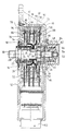
- Ein Ausführungsbeispiel der Erfindung ist nachstehend unter Bezugnahme auf die zugehörige Zeichnung näher erläutert, die einen Längsschnitt eines Stellungssensors für Landeklappenhebel bei Flugzeugen zeigt.
- Ein flaches Gehäuse 10 ist durch einen Deckel 12 abgeschlossen. In dem Deckel 12 sitzt ein hohlzylindrischer Lagerträger 14. Der Lagerträger 14 weist an seinem äußeren Ende einen Flansch 16 auf, welcher durch Schrauben 18 und Muttern 20 mit dem Deckel 12 verbunden ist. In dem Lagerträger 14 ist eine Eingangswelle 22 in Wälzlagern 24 und 26 um eine Achse 28 drehbar gelagert. Die Eingangswelle 22 weist einen mit einer Keilverzahnung versehenen, durch den Deckel 12 hindurchragenden Kopf 30 auf. Dieser Kopf ist mit einem (nicht dargestellten) Landeklappenhebel verbindbar.
- An dem inneren Ende ragt der Lagerträger 14 bis etwa zur Mitte in den Innenraum des Gehäuses 10 hinein.
- Das Gehäuse 10 weist auf der dem Kopf 30 gegenüberliegenden Seite Durchbruch 32 auf. Der Durchbruch 32 ist durch eine Kappe 34 abgedeckt, die mit einem Flansch 36 durch Schrauben 38 mit dem Gehäuse 10 verbunden ist. In die Kappe 34 ragt ein Ende 40 der Eingangswelle 22. Das Ende 40 der Eingangswelle 22 ist mit einer Keilverzahnung 42 versehen. Auf dem Ende 40 und der Keilverzahnung 42 sind Bremsscheiben 44 und 46 axial beweglich aber unverdrehbar geführt. Zwischen den Bremsscheiben 44 und 46 sitzt eine Reibscheibe 48, die beiderseits mit Bremsbelägen versehen und in einer Innenverzahnung 50 auf der Innenseite des Durchbruchs 32 unverdrehbar im Gehäuse 10 gehalten ist. Auf einem mit einem Gewinde versehenen Ende 52 der Eingangswelle 22 sitzt eine Mutter 54. An der Mutter 54 stützt sich ein Federwiderlager 56 ab. Auf einem mit einem Gewinde versehenen Mittelteil 58 der Eingangswelle 22 sitzt eine Mutter 60. Eine Schraubenfeder 62 umgibt die Eingangswelle 22 und liegt einerseits an dem Federwiderlager 56 und andererseits an der Bremsscheibe 46 an. Auf diese Weise wird durch die Vorspannung der Schraubenfeder 62 die Bremsscheibe 44 von links in der Figur über die Mutter 60 nach rechts gegen die Reibscheibe 48 gedrückt, während gleichzeitig durch die Feder die Bremsscheibe 46 nach links gegen die Reibscheibe 48 gedrückt wird. Diese Anordnung bildet eine Rutschkupplung welche die Eingangswelle 22 und damit die Kodierscheiben 78 und 88 im Falle eines Bruches der Eingangswelle 22 in der jeweils eingenommenen Stellung reibschlüssig festhält.
- In dem Gehäuse 10 sind zwei Paare von ringscheibenförmigen Leiterplatten 64, 66 und 68, 70 gehaltert. Die Leiterplatten 64, 66, 68, 70 liegen in Radialebenen bezogen auf die Achse 28. Sie sind somit parallel zueinander und weisen zentrale Durchbrüche auf, die koaxial zu der Achse 28 und der Eingangswelle 22 sind. Die Leiterplatten 64 und 66 eines Paares umgeben dabei den Lagerträger 14. Sie sind also axial im Bereich des Lagerträgers 14 angeordnet. Die anderen Leiterplatten 68 und 70 liegen in der Figur rechts von dem inneren Ende des Lagerträgers 14. Mit der Eingangswelle 22 ist ein Kodierscheibenträger 72 durch eine Nut- und -Federverbindung 74 drehfest verbunden. Der Kodierscheibenträger 72 greift mit einem topfförmigen Teil 70 um den Lagerträger 14 außen herum. Der topfförmige Teil 76 trägt an seinem Rand eine Kodierscheibe 78, welche zwischen das Paar 64, 66 von Leiterplatten ragt. In dem Gehäuse 10 sind weiterhin zwei Blendenscheiben 80 und 82 gehaltert. Die Blendenscheiben 80 und 82 sind zueinander und zu den Leiterplatten 64 und 66 parallel. Je eine Blendenscheibe 80 oder 82 ist zwischen jeder der Leiterplatten 64 bzw. 66 und der Kodierscheibe 78 angeordnet.
- Der Kodierscheibenträger 72 weist einen zweiten topfförmigen Teil 84 auf, der mit dem ersten topfförmigen Teil 76 Rücken-an-Rücken angeordnet ist. Der zweite topfförmige Teil 84 trägt eine zweite Kodierscheibe 88. Die zweite Kodierscheibe 88 ragt zwischen das zweite Paar 68, 70 von Leiterplatten. Ab hier ist im Gehäuse 10 und parallel zu den Leiterplatten 68 und 70 und der Kodierscheibe 88 jeweils zwischen jeder Leiterplatte 68 und 70 und der Kodierscheibe 88 eine Blendenscheibe 90 bzw. 92 gehäusefest angeordnet.
- Auf den Leiterplatten sitzen die optischen Sensoren. Die optischen Sensoren sind Lichtschranken, von denen jeweils ein Sender 94 bzw. 96 auf einer Leiterplatte 64 bzw. 68 und ein Empfänger 98 und 100 auf der anderen Leiterplatte 66 bzw. 70 angeordnet ist.
- Die Leiterplatten enthalten weitere elektronische Bauteile. Die Ausgangssignale des Stellungssensors werden über einen Anschlußstecker 102 ausgegeben.
Claims (7)
- Landeklappensteuerung bei Flugzeugen, mit einem Stellungssensor für Landeklappenhebel, dadurch gekennzeichnet, daß mit dem Landeklappenhebel über einer im Gehäuse (10) des Stellungssensors drehbar gelagerten Eingangswelle (22) eine Codierscheibe (78,80) verbunden ist, deren Stellung durch einen optischen Sensor (94,98;96,100) mit einer solchen Auflösung abtastbar ist, daß die von dem Landeklappenhebel eingegebenen Winkel direkt erfaßt werden können.
- Landeklappensteuerung nach Anspruch 1, dadurch gekennzeichnet, daß Codierscheibe (78; 88) und optischer Sensor (94, 98; 96, 100) vermehrfacht vorgesehen sind.
- Landeklappensteuerung nach Anspruch 1, gekennzeichnet durch(a) wenigstens zwei in dem Gehäuse (10) parallel zueinander und koaxial zu der Eingangswelle gehalterte, ringscheibenförmige Leiterplatten (64, 66; 68, 70),(b) optische Sensoren (94, 98; 96, 100) auf den Leiterplatten (64, 66; 68, 70) und(c) eine Codierscheibe (78, 88), die drehfest mit der Eingangswelle (22) verbunden ist, zwischen die Leiterplatten (64, 66; 68, 70) ragt und mit den optischen Sensoren (94, 98; 96, 100) zusammenwirkt.
- Landeklappensteuerung nach Anspruch 3, dadurch gekennzeichnet, daß die optischen Sensoren Lichtschranken (94, 98; 96, 100) sind, von denen jeweils ein Sender (94, 96) auf einer Leiterplatte (64, 68) und ein Empfänger (98, 100) auf der anderen Leiterplatte (66, 70) angeordnet ist.
- Landeklappensteuerung nach Anspruch 4, dadurch gekennzeichnet, daß im Gehäuse (10) und parallel zu den Leiterplatten (64, 66; 68, 70) und der Codierscheibe (78, 88) jeweils zwischen jeder Leiterplatte (64, 66 bzw. 68, 70) und der Codierscheibe (78, 88) eine Blendenscheibe (80, 82; 90, 92) angeordnet ist.
- Landeklappensteuerung nach den Ansprüchen 2 und 3, dadurch gekennzeichnet, daß(a) an einer Stirnwand des Gehäuses (10) ein hohlzylindrischer Lagerträger (14) befestigt ist, der in den Innenraum des Gehäuses (10) hineinragt,(b) die Eingangswelle (22) mittels wenigstens zweier Wälzlager (24, 26) in dem Lagerträger (14) gelagert ist,(c) in dem Gehäuse (10) zweier Paare von parallelen ringscheibenförmigen Leiterplatten (64, 66; 68, 70) gehaltert sind, wobei die Leiterplatten (64, 68) eines Paares den Lagerträger (14) umgeben,(d) mit der Eingangswelle (22) ein Codierscheibenträger (72) drehfest verbunden ist, der mit einem topfförmigen Teil (76) um den Lagerträger (14) außen herumgreift und eine zwischen das besagte Paar von Leiterplatten (64, 66) ragende Codierscheibe (78) trägt.
- Landeklappensteuerung nach Anspruch 6, dadurch gekennzeichnet, daß der Codierscheibenträger (72) einen zweiten topfförmigen Teil (84) aufweist, der mit dem besagten ersten topfförmigen Teil (76) Rücken-an-Rücken angeordnet ist und eine zweite Codierscheibe (88) trägt, die zwischen das zweite Paar von Leiterplatten (68, 70) ragt.
Applications Claiming Priority (2)
| Application Number | Priority Date | Filing Date | Title |
|---|---|---|---|
| DE3939132A DE3939132A1 (de) | 1989-11-27 | 1989-11-27 | Stellungssensor fuer landeklappenhebel bei flugzeugen |
| DE3939132 | 1989-11-27 |
Publications (2)
| Publication Number | Publication Date |
|---|---|
| EP0429939A1 EP0429939A1 (de) | 1991-06-05 |
| EP0429939B1 true EP0429939B1 (de) | 1995-06-28 |
Family
ID=6394248
Family Applications (1)
| Application Number | Title | Priority Date | Filing Date |
|---|---|---|---|
| EP90121608A Expired - Lifetime EP0429939B1 (de) | 1989-11-27 | 1990-11-12 | Stellungssensor für Landeklappenhebel bei Flugzeugen |
Country Status (2)
| Country | Link |
|---|---|
| EP (1) | EP0429939B1 (de) |
| DE (3) | DE3939132A1 (de) |
Cited By (1)
| Publication number | Priority date | Publication date | Assignee | Title |
|---|---|---|---|---|
| US12351295B2 (en) | 2022-11-21 | 2025-07-08 | Hamilton Sundstrand Corporation | Fiber optic slat flap system and control lever |
Families Citing this family (5)
| Publication number | Priority date | Publication date | Assignee | Title |
|---|---|---|---|---|
| DE4042302A1 (de) * | 1990-12-31 | 1992-07-09 | Bodenseewerk Geraetetech | Schaltstellungssensor |
| DE4331230B4 (de) * | 1993-09-15 | 2008-04-17 | Diehl Aerospace Gmbh | Steuerhebelgerät für die Einstellung der Schubkraft bei Flugzeugen |
| DE10249967B4 (de) * | 2002-10-26 | 2006-03-09 | Airbus Deutschland Gmbh | Vorrichtung zur Ansteuerung der Vorflügel und Landeklappen eines Flugzeuges |
| DE102008034444B4 (de) * | 2008-05-14 | 2013-09-05 | Diehl Aerospace Gmbh | Eingabesystem für eine Landeklappensteuerung eines Flugzeugs |
| DE102008038956A1 (de) * | 2008-08-13 | 2010-03-04 | Diehl Aerospace Gmbh | Landeklappensensoreinheit |
Family Cites Families (19)
| Publication number | Priority date | Publication date | Assignee | Title |
|---|---|---|---|---|
| DE2646674A1 (de) * | 1974-09-30 | 1977-04-21 | Keystone Int | Lageempfindliches abtast-bedienungssystem |
| DE2837743C3 (de) * | 1978-08-30 | 1982-02-04 | Frankl & Kirchner GmbH & Co KG Fabrik für Elektromotoren u.elektrische Apparate, 6830 Schwetzingen | Opto-elektronischer Positionsgeber |
| DE2919431A1 (de) * | 1979-05-15 | 1980-11-27 | Ver Flugtechnische Werke | Steuereinrichtung zum einstellen von luftfahrzeugsteuerflaechen |
| US4333009A (en) * | 1979-12-10 | 1982-06-01 | Bertea Corporation | Optical position transducer |
| DE3032918C2 (de) * | 1980-09-02 | 1984-05-30 | Messerschmitt-Bölkow-Blohm GmbH, 8012 Ottobrunn | Passives Leitungssystem, insbesondere für Luftfahrzeuge, zur Übertragung von Steuersignalen |
| DE3111722C2 (de) * | 1981-03-25 | 1984-11-15 | Messerschmitt-Bölkow-Blohm GmbH, 8000 München | Passives Leitungssystem für Luftfahrzeuge zur Übertragung von Steuersignalen |
| IT1129862B (it) * | 1980-11-17 | 1986-06-11 | Olivetti & Co Spa | Trasduttore ottico |
| DE3221621C2 (de) * | 1982-06-08 | 1985-10-03 | Zahnräderfabrik Renk AG, 8900 Augsburg | Fotoelektrischer Stellungsgeber für Antriebsanlagen von Fahrzeugen |
| US4559524A (en) * | 1983-06-17 | 1985-12-17 | Sumtak Corporation | Rotary encoder |
| US4654522A (en) * | 1983-09-22 | 1987-03-31 | Cts Corporation | Miniature position encoder with radially non-aligned light emitters and detectors |
| DE8416558U1 (de) * | 1984-05-30 | 1986-04-10 | Dr. Johannes Heidenhain Gmbh, 8225 Traunreut | Positionsmeßeinrichtung |
| DE3444878A1 (de) * | 1984-12-08 | 1986-06-12 | Bodenseewerk Gerätetechnik GmbH, 7770 Überlingen | Abtastkopf fuer schrittgeber, insbesondere winkelschrittgeber |
| EP0187875A1 (de) * | 1985-01-02 | 1986-07-23 | ITALORA S.p.A. | Digitaltransduktor |
| DE3505810A1 (de) * | 1985-02-20 | 1986-08-21 | Licentia Patent-Verwaltungs-Gmbh, 6000 Frankfurt | Anordnung zur ermittlung der verstellung bzw. einstellung eines weges oder winkels |
| DE3737278A1 (de) * | 1986-11-04 | 1988-05-11 | Canon Kk | Verfahren und vorrichtung zum optischen erfassen der stellung eines objekts |
| DE3638455A1 (de) * | 1986-11-11 | 1988-06-01 | Licentia Gmbh | Vorrichtung zur stoerungsfreien ermittlung der verstellung bzw. einstellung eines winkels oder weges eines codierte informationen aufweisenden traegers |
| DE3716464A1 (de) * | 1987-05-16 | 1988-12-08 | Danfoss As | Rotationsmaschine mit drehwinkel-messvorrichtung |
| DE3820906A1 (de) * | 1988-06-21 | 1989-12-28 | Bodenseewerk Geraetetech | Winkelabgriff hoher aufloesung |
| DE3822007A1 (de) * | 1988-06-30 | 1990-01-04 | Bodenseewerk Geraetetech | Digitaler lagesignalgeber |
-
1989
- 1989-11-27 DE DE3939132A patent/DE3939132A1/de not_active Withdrawn
- 1989-11-27 DE DE8915839U patent/DE8915839U1/de not_active Expired - Lifetime
-
1990
- 1990-11-12 EP EP90121608A patent/EP0429939B1/de not_active Expired - Lifetime
- 1990-11-12 DE DE59009339T patent/DE59009339D1/de not_active Expired - Lifetime
Non-Patent Citations (1)
| Title |
|---|
| US; ""Thumball" auxiliary data-input device" * |
Cited By (1)
| Publication number | Priority date | Publication date | Assignee | Title |
|---|---|---|---|---|
| US12351295B2 (en) | 2022-11-21 | 2025-07-08 | Hamilton Sundstrand Corporation | Fiber optic slat flap system and control lever |
Also Published As
| Publication number | Publication date |
|---|---|
| DE8915839U1 (de) | 1992-01-16 |
| EP0429939A1 (de) | 1991-06-05 |
| DE3939132A1 (de) | 1991-05-29 |
| DE59009339D1 (de) | 1995-08-03 |
Similar Documents
| Publication | Publication Date | Title |
|---|---|---|
| DE69814062T2 (de) | Elektronisches flugzeugbremssystem mit verschleissmessung, spielnachstellung und mehreren elektromotor-betätigungseinheiten | |
| DE69410226T2 (de) | Aktives Handsteuerungssystem | |
| DE102008008835B4 (de) | Vorrichtung zum Ermitteln eines Drehmoments | |
| EP0599083B1 (de) | Antriebseinheit zur Steuerung und Regelung von Armaturen od.dgl. | |
| EP0447626A2 (de) | Aktuator für eine kybernetisce Lenkung | |
| WO2008012123A1 (de) | Aktuator mit funktionsüberwachung | |
| EP1880923B1 (de) | Lenkantrieb für ein Rad eines Flurförderzeugs mit einer Vorrichtung zur Erfassung des Ist-Winkels des gelenkten Rades | |
| DE112019000464T5 (de) | Einrichtung zur verwendung beim drehen lenkbarer fahrzeugräder | |
| EP0389669A1 (de) | Lenkwinkelsensor | |
| DE69407059T2 (de) | Drucklager für ein stellglied das eine sensorvorrichtung betätigt | |
| DE69723462T2 (de) | Drehmomentenübertragungsvorrichtung | |
| EP1979209A1 (de) | Stelleinrichtung, insbesondere für eine kraftfahrzeug-feststellbremse | |
| DE102021125497A1 (de) | Radmodul für ein Fahrzeug mit einer Steer-by-Wire-Lenkeinrichtung | |
| DE112008000262B4 (de) | Bidirektionale Motorsteueranordnung | |
| EP0429939A1 (de) | Stellungssensor für Landeklappenhebel bei Flugzeugen | |
| EP0805412A1 (de) | Steuereinrichtung, insbesondere für die Steuerung von Maschinen | |
| EP1511982A1 (de) | Messvorrichtung zum messen von positionen oder bewegungen | |
| DE102020123965A1 (de) | Spindeltriebanordnung, Lenkeinheit und Fahrwerksaktuator | |
| DE69212250T2 (de) | Drehantrieb zur Erzeugung eines durch adaptierbare Steuerkennlinien veränderbaren Drehmoments am Steuerrad eines Steuersystems | |
| DE10201141B4 (de) | Stellgetriebe mit Einrichtungen zur Feststellung der Abweichung von einer vorgegebenen Ausgangsstellung | |
| DE10054938C2 (de) | Modul einer elektromechanisch betätigbaren Scheibenbremse und Scheibenbremse mit einem solchen Modul | |
| DE4345557B4 (de) | Motorgetriebene Drosselklappenvorrichtung für einen Verbrennungsmotor | |
| EP0537415A1 (de) | Inertialsensor | |
| DE3612619C2 (de) | ||
| DE102022120307A1 (de) | Fahrwerksaktuator |
Legal Events
| Date | Code | Title | Description |
|---|---|---|---|
| PUAI | Public reference made under article 153(3) epc to a published international application that has entered the european phase |
Free format text: ORIGINAL CODE: 0009012 |
|
| AK | Designated contracting states |
Kind code of ref document: A1 Designated state(s): DE FR GB |
|
| 17P | Request for examination filed |
Effective date: 19911009 |
|
| 17Q | First examination report despatched |
Effective date: 19921126 |
|
| GRAA | (expected) grant |
Free format text: ORIGINAL CODE: 0009210 |
|
| AK | Designated contracting states |
Kind code of ref document: B1 Designated state(s): DE FR GB |
|
| REF | Corresponds to: |
Ref document number: 59009339 Country of ref document: DE Date of ref document: 19950803 |
|
| GBT | Gb: translation of ep patent filed (gb section 77(6)(a)/1977) |
Effective date: 19950822 |
|
| ET | Fr: translation filed | ||
| PLBE | No opposition filed within time limit |
Free format text: ORIGINAL CODE: 0009261 |
|
| STAA | Information on the status of an ep patent application or granted ep patent |
Free format text: STATUS: NO OPPOSITION FILED WITHIN TIME LIMIT |
|
| 26N | No opposition filed | ||
| REG | Reference to a national code |
Ref country code: GB Ref legal event code: IF02 |
|
| PGFP | Annual fee paid to national office [announced via postgrant information from national office to epo] |
Ref country code: GB Payment date: 20091126 Year of fee payment: 20 Ref country code: FR Payment date: 20091113 Year of fee payment: 20 |
|
| PGFP | Annual fee paid to national office [announced via postgrant information from national office to epo] |
Ref country code: DE Payment date: 20100120 Year of fee payment: 20 |
|
| REG | Reference to a national code |
Ref country code: GB Ref legal event code: PE20 Expiry date: 20101111 |
|
| PG25 | Lapsed in a contracting state [announced via postgrant information from national office to epo] |
Ref country code: GB Free format text: LAPSE BECAUSE OF EXPIRATION OF PROTECTION Effective date: 20101111 |
|
| PG25 | Lapsed in a contracting state [announced via postgrant information from national office to epo] |
Ref country code: DE Free format text: LAPSE BECAUSE OF EXPIRATION OF PROTECTION Effective date: 20101112 |