EP0429805A2 - Verfahren und Vorrichtung zur Herstellung einer plissierten Filtereinlage - Google Patents
Verfahren und Vorrichtung zur Herstellung einer plissierten Filtereinlage Download PDFInfo
- Publication number
- EP0429805A2 EP0429805A2 EP90119290A EP90119290A EP0429805A2 EP 0429805 A2 EP0429805 A2 EP 0429805A2 EP 90119290 A EP90119290 A EP 90119290A EP 90119290 A EP90119290 A EP 90119290A EP 0429805 A2 EP0429805 A2 EP 0429805A2
- Authority
- EP
- European Patent Office
- Prior art keywords
- filter material
- temperature
- filter
- jaws
- bulges
- Prior art date
- Legal status (The legal status is an assumption and is not a legal conclusion. Google has not performed a legal analysis and makes no representation as to the accuracy of the status listed.)
- Granted
Links
Images
Classifications
-
- B—PERFORMING OPERATIONS; TRANSPORTING
- B31—MAKING ARTICLES OF PAPER, CARDBOARD OR MATERIAL WORKED IN A MANNER ANALOGOUS TO PAPER; WORKING PAPER, CARDBOARD OR MATERIAL WORKED IN A MANNER ANALOGOUS TO PAPER
- B31D—MAKING ARTICLES OF PAPER, CARDBOARD OR MATERIAL WORKED IN A MANNER ANALOGOUS TO PAPER, NOT PROVIDED FOR IN SUBCLASSES B31B OR B31C
- B31D5/00—Multiple-step processes for making three-dimensional articles ; Making three-dimensional articles
- B31D5/0082—Making filter elements, e.g. pleated
-
- B—PERFORMING OPERATIONS; TRANSPORTING
- B31—MAKING ARTICLES OF PAPER, CARDBOARD OR MATERIAL WORKED IN A MANNER ANALOGOUS TO PAPER; WORKING PAPER, CARDBOARD OR MATERIAL WORKED IN A MANNER ANALOGOUS TO PAPER
- B31F—MECHANICAL WORKING OR DEFORMATION OF PAPER, CARDBOARD OR MATERIAL WORKED IN A MANNER ANALOGOUS TO PAPER
- B31F1/00—Mechanical deformation without removing material, e.g. in combination with laminating
- B31F1/20—Corrugating; Corrugating combined with laminating to other layers
Definitions
- the present invention relates to a method and a device for producing a pleated filter insert made of a thermoplastic material for filter material provided between the inflow side and the outflow side of a filter, with a plurality of filter folds spacing the pleat walls from one another at least in the filter folds open towards the outflow side of the filter. elongated bulges formed from the filter material itself.
- the filter material which can also consist of a thermoplastic
- the press consists of two heated cylinders which are rotatable in the opposite direction and are provided with interlocking bulges and depressions which are provided for forming bulges and indentations in the filter material.
- the filter material is provided between these two heated cylinders with the elongated recesses and indentations intended for the spacing of the filter fold walls and with transverse grooves to facilitate the formation of folded edges.
- the filter material is permanently deformed between the two heated cylinders by deep drawing.
- Deep drawing also changes the structure of the filter material in the deep-drawn area. Therefore, the filter material permanently deformed by this process cannot retain the original filter properties in the areas that are important for filtration. It is therefore necessary to choose a larger, more costly filter insert if you want to achieve the same filtering effect as with a filter insert with completely effective filter walls.
- FIG. 1 Another device for producing a pleated filter insert is known from FR-A1 2,273,657.
- an expandable filter material is first provided with alternately convex and concave longitudinal grooves between rollers while changing the material structure by stretching the filter material.
- the filter material thus prepared is folded across the longitudinal grooves in a second step in order to obtain the pleated filter insert.
- an expandable filter material In order to be able to fold the filter material provided with longitudinal grooves across the longitudinal grooves, an expandable filter material must be used.
- the filter materials that are mostly used cannot be stretched, or at least not without changing the filter properties of the filter material. Therefore, this device can only be used for special, stretchable filter materials.
- the fold edges lying at the folds which are transverse to the longitudinal grooves also have undesirable unevenness, which at least complicates the cleaning of the filter insert.
- the object of the present invention is to provide a method and a device for producing a filter insert made of a thermoplastic material with spaced, elongated bulges present at least in the downstream filter folds, the filter properties of the filter material in the fold walls during production despite deformation of the filter material should be preserved and the finished filter insert should have sufficient stability and smooth folding edges which facilitate cleaning of the filter insert and should be economically advantageous.
- the band-shaped filter material which is intended for the production of at least one filter insert and is transported in the longitudinal direction, is reduced in a first process step transversely to the longitudinal direction by the additional material required for the elongated bulges by gathering evenly distributed over the entire width that the elongated bulges are produced by a tension-free, permanent shaping of the shirred filter material, which is heated to a temperature below the shrinking temperature and above the shaping temperature of the filter material, between the jaws of a shaping device and by a subsequent cooling of the filter material falling below the shaping temperature, and that the provided for the formation of folded edges, linear areas of the filter material by at least one heating jaw to a between the deformation temperature and the melt z temperature lying temperature are heated until the unevenness caused by the elongated bulges and / or by gathering the filter material are compensated and then cooled to a temperature below the deformation temperature.
- This process enables the production of a filter insert made of thermoplastic material, in which the fold walls retain the original filter properties of the filter material despite the bulges, and the folded edges have a smooth surface that is easy to clean.
- the thermally treated folded edges also ensure good stability of the filter insert with their relatively high rigidity.
- the filter material is drawn during the thermal treatment carried out by a heating jaw at the linear folded edges and there becomes narrower than the width of the untreated filter material by the additional material required for the elongated bulges.
- the shortened folded edges keep the elongated bulges in shape even with the strongest operational flow and contamination of the medium to be filtered and do not let them stretch in the filter insert.
- the filter inserts produced by this method are also economically advantageous, because additional measures are not necessary to achieve sufficient rigidity of the filter insert, nor to keep the pleated walls in the filter folds, the filter properties of the filter insert nevertheless being as effective as possible due to the fully effective pleated walls stay secured.
- the gathered filter material Before being fed to the jaws of the shaping device, the gathered filter material can be heated to a temperature below the shrinking temperature and above the shaping temperature and then guided between the jaws of the shaping device. In a continuous process, this measure can increase the throughput speed of the filter material.
- the gathered filter material is advantageously first passed between first jaws heated to a temperature below the shrinking temperature and above the shaping temperature and then between second jaws of the shaping device cooled below the shaping temperature, and then the filter material thus provided with longitudinal grooves at regular intervals in the for the formation of Provided filter edges, linear areas under at least one heating jaw to a temperature between the deformation temperature and the melting temperature until the unevenness caused by the longitudinal grooves compensate.
- At least two successive fold wall areas of the filter material which accommodate the elongate bulges, can be formed stress-free between the jaws of a press heated to a temperature below the shrinking temperature and above the deformation temperature of the filter material, and each between the individual fold wall areas held in the press the exposed intermediate area of the filter material, intended for the formation of folded edges, are heated to a temperature lying between the deformation temperature and the melting temperature, until the unevenness of the filter material in the intermediate area compensates.
- both a plurality of fold wall regions and the regions provided in between for the fold edges are permanently formed in one operation.
- the longitudinal direction of the elongated bulges lying between the jaws of the press to the longitudinal direction of the fold walls can be set at an angle of 45 ° to 90 °. This measure ensures that the elongated bulges in the filter folds at least once at 90 ° and twice at other angle values by crossing.
- the intersecting elongated bulges keep the distance between the fold walls, but reduce the effective filter area only by the point-like contact points between them.
- the successive fold wall regions can be held at an acute angle to one another in the press and a fold edge can be formed in each intermediate region of the filter material which is exposed between the individual fold wall regions and heated to a temperature lying between the deformation temperature and the melting temperature.
- the line-shaped areas of the filter material provided for the formation of fold edges are advantageously heated by at least one heating jaw to a temperature lying between the shrinking temperature and the melting temperature until the unevenness caused by the elongated bulges and / or by the gathering of the filter material are compensated.
- a particularly stable, linear region is achieved at the fold edges of the filter insert, as a result of which the filter insert can maintain its stability even under special conditions.
- a device provided for carrying out the method is characterized in that for the gathering of the filter material there are provided a plurality of rounded projections, which are distributed transversely to the longitudinal direction of the filter material, that the shaping device consists of at least one heating device intended for the filter material and at least two the tension-free, permanent shape required for the elongated bulges tion of the filter material carrying jaws and that for the production of the intended for the formation of filter edges, linear, free of unevenness areas of the filter material at least one heating jaw is only effective for these areas.
- This device is simple and economically advantageous.
- Two jaws thermally insulated from one another in the longitudinal direction of the filter material can be provided for the shaping device, the filter material being guided in the running direction first between the jaws having a temperature below the shrinking temperature and above the deformation temperature and then between the jaws having a temperature below the deformation temperature .
- a shaping device with interlocking oblique grooves and inclined ribs that are divided transversely to the longitudinal direction of the filter material can be provided, the jaws transversely to the longitudinal direction of the band-shaped filter material having one of the lateral displacement speeds of the bevels Carry out corresponding movement of the bulges.
- At least one transport gripper is provided, which carries out a stepwise advance of the band-shaped filter material that corresponds at least to the simple distance between two folded edges of the filter insert.
- the heating jaw provided for the formation of filter edges can be used simply by lowering and then lifting.
- the device can open at least three filter material that can be closed in the longitudinal direction of the elongate bulges provided in the fold walls, with their tips alternately oriented in the opposite direction, with a trapezoidal cross-section and with at least one trapezoidal jaw that interacts with the tip of each of the two outer jaws a heating bake heating between the shrink temperature and the melting temperature of the filter material.
- the inclined sides of the jaws which are trapezoidal in cross section, can form an angle between 5 ° and 70 °.
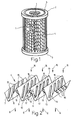
- the filter device shown partly in section in FIG. 1 consists of a tube 1 provided with holes, two flanges 2, 3 fastened to the tube 1 and a pleated filter insert 4 inserted between the two flanges 2, 3.
- the flange 2 is with a groove 5 provided for a sealing ring.
- the filter device is shown in FIG. 1 without a housing and connection devices.
- the gaseous or liquid medium to be filtered is fed through the housing, not shown, radially from the outside to the inflow side of the filter insert.
- the tube 1 provided with holes lies on the outflow side of the filter insert 4.
- the filtered medium is guided axially out of the tube 1 through a connection piece (not shown).
- the pleated filter insert 4 consists of a thermoplastic filter material.
- Such filter materials are available on the market and are made from a known thermoplastic material such as polyethylene, polypropylene, polyester, polyamide, polytetrafluoroethylene, etc. 2 shows an enlarged section of the pleated filter insert 4 shown in FIG. 1.
- this figure clearly shows that in the filter folds open toward the outflow side indicated by the arrows 6, the pleated walls 7 to 14 are spaced apart by elongated bulges 15 are when you squeeze the filter pleats.
- the bulges 15 are formed from the filter material itself and protrude into the filter folds on the outflow side.
- the longitudinal direction of the bulges 15 is at an angle of approximately 70 'to the longitudinal direction of the fold walls 7 to 14.
- the bulges 15 intersect in the downstream filter folds and only touch one another in a punctiform manner, as a result of which the filter material in all pleated walls 7 to 14 practically without loss of area for the filtration really is sam.
- the upstream filter folds are kept open in the filter device shown in Fig.1 by the round arrangement. If the filter pleats were arranged one behind the other in a plane, bulges protruding from the filter material could be provided on both sides.
- the inflow side of the filter insert 4 is indicated by the arrows 16 in FIG.
- the filter material provided for the filter insert 4 is prepared using a method.
- the band-shaped filter material transported in the longitudinal direction is transversely to the longitudinal direction in a first process step the elongated bulges necessary, additional material requirements reduced by shirring evenly distributed over the entire width.
- the elongated bulges are then created by a tension-free, permanent shaping of the filter material between the jaws of a shaping device.
- the filter material to be molded is heated to a temperature below the shrinking temperature and above the deformation temperature of the filter material.
- the filter material is cooled below the shaping temperature.
- the line-shaped areas of the filter material provided for the formation of folded edges are heated by at least one heating jaw to a temperature lying between the shrinking temperature and the melting temperature until the unevenness caused by the elongated bulges and / or the gathering of the filter material is compensated for by material deformation .
- These areas, which have become smooth, are then cooled to a temperature below the deformation temperature.
- the filter insert 4 thus formed from the filter material has the original filter properties on the fold walls 7 to 14 despite bulges 15 and smooth, clean foldable edges.
- the thermally treated, relatively stiff folded edges also result in good stability for the filter insert 4.
- the filter material contracts permanently on the linear folded edges during the thermal treatment carried out by a heating jaw and is there narrower than the additional material required for the elongated bulges the width of the untreated filter material.
- the shortened folded edges keep the elongated bulges in shape even with the strongest operational flow and contamination of the medium to be filtered and do not let them stretch in the filter insert.
- the gathered filter material is heated to a temperature below the shrinking temperature and above the forming temperature before being fed to the jaws of the shaping device and is then guided between the jaws of the shaping device.
- the preheated filter material is smoother than the cold one and is easier to insert between the jaws of the forming device.
- the gathered filter material is first passed between two heated and then between two cooled jaws of the shaping device.
- the heated jaws are below the shrinking temperature and above the deformation temperature, depending on the filter material used, generally between 60 ° C and 140 ° C.
- the cooled jaws have a temperature below the deformation temperature.
- the filter material provided with longitudinal grooves after passing through these jaws is heated at regular intervals, in the areas provided for filter edges, by heating jaws to a temperature between the deformation temperature and the melting temperature until the unevenness caused by the longitudinal grooves is compensated.
- the filter insert 4 can be produced in a single main process step after a further development of the method after gathering the filter material.
- two successive, the elongated bulges 15 to accommodate certain pleated wall areas 17, 18 of the filter material between the jaws of a press are held individually and relaxed. It is important that the filter material is not warped or stretched between the jaws of the press in order not to change the filter properties of the filter material.
- the intermediate region 19 is heated to a temperature lying between the deformation temperature and the melting temperature of the filter material. Under the influence of heat, the intermediate region 19 deforms permanently, after which a smooth surface remains without unevenness.
- the acute-angled folded edge lying between the fold wall regions 17, 18 is also formed, because the jaws of the press hold the successive fold wall regions 17, 18 at an angle of approximately 45 during the heating of the intermediate region 19.
- all of the bulges 15, intermediate areas 19 and folded edges of the entire filter insert 4 are brought into the desired shape.
- the jaws of the press and thus the fold wall regions 17, 18 are heated to a temperature below the shrinking temperature and above the deformation temperature of the filter material during the pressing.
- the filter properties of the filter material are not impaired at this temperature, but the filter material undergoes permanent deformation.
- the deformation temperature, the shrinking temperature and the melting temperature of the filter material can be taken from the manufacturer's information or from our own tests.
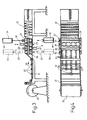
- a device which is shown schematically in FIGS. 3 and 4 from the side and from above is provided for carrying out the described method.
- a grooved table 21 has been selected. Heated rollers 22 are assigned to the grooves and press the filter material 20 into the grooves.
- the main process step takes place in a subsequent press.
- the press has four heatable jaws 23, 24, 25, 26 with a trapezoidal cross section, between which the filter material 20 is clamped and held to form the elongated bulges 15.
- the jaws 23, 24, 25, 26 are inserted in the lateral guide and drive parts 27, 28 in holders which in turn can be displaced in the longitudinal direction 29 by a chain drive (not shown in more detail).
- heating jaws 30, 31 which heat the filter material in the intermediate areas 19 shown in FIG. 2 between two fold wall areas 17, 18 held in the press to a temperature lying between the shrinking temperature and the melting temperature.
- the heating jaws 30, 31 cooperate with the tips of the jaws 24, 25 which are trapezoidal in cross section and lie between the two outer jaws 23, 26.
- the fully deformed, pleated filter insert is collected in a magazine 32 after the press.
- the device shown in Figures 3 and 4 works as described below.
- the filter material 20 is guided to the grooved table 21, where the heated rollers 22 form longitudinal grooves 33 into the filter material.
- the temperature of the rollers 22 is below the shrinking temperature of the selected filter material.
- the filter material gathered in this way is clamped between the jaws 23, 24, 25, 26 of the press which are provided with cooperating elevations and depressions for the formation of the elongated bulges 15.
- the jaws 23, 24, 25, 26 are brought to a temperature below the shrinking temperature and above the deformation temperature of the filter material.
- the jaws 23, 24, 25, 26 close one after the other in the longitudinal direction of the elongate bulges 15 present in the fold walls 7 to 14.
- the heating jaws 30, 31 close and heat the intermediate regions 19 shown in FIG. 2 to a temperature above the shrinking temperature and below the melting temperature of the filter material.
- the heating jaws 30, 31 can act punctiformly on protruding filter material parts or linearly over the entire length of the intermediate regions 19.
- a known heating device such as ultrasonic or infrared heating, which is available on the market, is used for heating the heating jaws 30, 31.
- the filter material contracts under the heating jaws 30, 31. After removal of the heating jaws 30, 31, the filter material in the intermediate areas 19 forming the folded edges is smooth and relatively stiff. The smooth folded edges are easy to clean. The rigidity of the folded edges gives the filter insert 4 good stability.
- the foremost jaw 23 is lifted out of the holders of the drive parts 27, 28 by a gripping and lifting device 34 and the further jaws 24, 25, 26 are pushed forwards, in FIG. 3 to the right.
- the gripping and lifting device 34 and the jaw 23 attached to it are now moved backwards, to the left in FIG.
- the jaw 23 is now inserted into the first gap instead of the jaw 26 now pushed further into the holders of the drive parts 27, 28.
- the gripping and lifting device 34 then returns to the rest position.
- a second gripping and lifting device 35 now pulls the jaw 24 out of the row of the other jaws 25, 26, 23. After the front jaw 24 is now pulled out, the remaining three jaws 25, 26, 23 are pushed forward. The gripping and lifting device 35 is then pushed back with the jaws 24 attached to it and the jaws 24 at the last point, behind the jaws 23, are inserted into the holders of the drive parts 27, 28. Now the second gripping and lifting device 35 also returns to the rest position. After these jaw movements, fresh, uneven filter material is again under the heating jaws 30, 31, because the filter material has been drawn from the material roll by the displacement of the jaws 25, 26, 23, 24.
- the fold wall regions 17, 18 with the elongated bulges 15 are clamped between the jaws 25, 26, 23, 24 of the press.
- the heating jaws 30, 31 close again and bring the filter material underneath to a temperature between the shrinking temperature and the melting temperature of the filter material.
- the first jaws 23, 24, 25, 26 outside the row of jaws 23, 24, 25, 26 are repeatedly brought from the first to the last position and the remaining jaws 23, 24, 25, 26 in the row of jaws 23, 24, 25, 26 pushed forward.
- the finished filter insert 4 is pressed into the magazine 32.
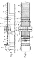
- FIGS. 5 to 8 show a further embodiment variant of a device provided for carrying out the described method.
- Fig. 5 shows the device from the side and Fig. 6 from above schematically.
- a schematic representation is necessary because of the better clarity of the functionally essential elements. All guiding and actuating elements have been omitted in FIGS. 4 to 8. All suitable management and actuating elements available on the market can be used for this.
- the filter material 36 is rolled up according to FIG. 5.
- a table 37 there are a plurality of rounded projections 38, which are staggered on both sides from the center, intermeshed like a comb from above and from below, which are formed at the top from rollers and at the bottom from grooves machined into the table surface.
- the filter material 36 is guided between these projections 38 and thus narrowed and gathered.
- a heating device 39 directed towards the filter material 36.
- the shaping device with the two jaws 40, 41.
- the jaws 40 are brought to a temperature below that with a heating rod 42 shown schematically in FIG the shrink temperature and above the deformation temperature, heated.
- the jaws 41 are cooled below the deformation temperature with the air flow indicated by the arrows 43.
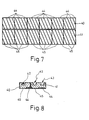
- 8 shows the upper half of the jaws 40, 41 in cross section.
- 7 shows the top view of the lower halves of the jaws 40, 41 with the upper jaws removed.
- the jaws 40, 41 are divided transversely to the longitudinal direction of the band-shaped filter material 36 and provided with oblique grooves 44 and oblique ribs 45, the oblique ribs 45 penetrating into the oblique grooves of the counterpart in the upper half of the jaws 40, 41 and vice versa.
- the individual parts of the jaws 40, 41 are guided such that they run along the oblique grooves of the filter material 36 transversely to the longitudinal direction of the filter material 36 and, after leaving the side edge of the filter material 36, are lifted or lowered out of line and to the beginning of the moving parts the jaws 40, 41 are returned.
- Two pneumatic, gripper-like transport grippers 46, 47 are provided, which transport the filter material 36 in batches by twice the distance between two fold edges 48 of the filter insert 4.
- the transport grippers 46, 47 there are four lifting and lowering heating jaws 49.
- the closed heating jaws 49 touching the filter material 36 heat the filter material 36 to a temperature lying between the deformation temperature and the melting temperature.
- the filter material is folded in a later process step, not described in detail.
- the heating jaws 49 can additionally alternately impress alternately opposing buckling edges in the areas of the filter material intended for the folding edges. These fold edges consist of alternately oppositely directed grooves which run transversely to the longitudinal direction of the filter material.
- the device shown in Figures 5 to 8 works as described below.
- the beginning of the filter material 36 is first placed in the device. Thereafter, the heating device 39, the heating rods 42 in the jaws 40, the air cooling for the jaws 41 and the control of the entire device, not described and shown, are switched on.
- the control switches on the transport grippers 46, 47.
- the edges of the transport grippers 46, 47 padded with a soft material grasp the filter material 36 and draw this by twice the distance between two adjacent fold edges 48 of the filter insert 4.
- the four heating jaws 49 close and heat the filter material 36 in two successive areas intended for the formation of fold edges 48 to a temperature lying between the deformation temperature and the melting temperature, until the temperature caused by the elongated bulges and / or unevenness caused by the gathering of the filter material is compensated. During this time, the transport grippers 46, 47 move apart and return to the starting position. After the unevenness has been compensated for, the heating jaws 49 are removed from the filter material 36, whereupon the filter material 36 cools below the deformation temperature. If necessary, cooling can take place under a forced air flow.
- the transport grippers 46, 47 grip the filter material 36 again and the sequence of steps just described begins from before no While the filter material 36 is being transported, the jaws 40, 41 of the shaping device move at a speed corresponding to the lateral displacement speed of the inclined grooves 44 and inclined ribs 45 of the filter material 36 transversely to the longitudinal direction of the filter material 36 in the arrow direction 50 shown in FIG separated part of the jaws 40, 41 has moved beyond the edge of the filter material, it is lifted out of the row and returned to the beginning of the row of jaws 40, 41 in a return device (not shown).
Landscapes
- Engineering & Computer Science (AREA)
- Mechanical Engineering (AREA)
- Filtering Materials (AREA)
- Filtering Of Dispersed Particles In Gases (AREA)
- Shaping Of Tube Ends By Bending Or Straightening (AREA)
- Filtration Of Liquid (AREA)
- Separation Using Semi-Permeable Membranes (AREA)
Abstract
Description
- Die vorliegende Erfindung betrifft ein Verfahren und eine Vorrichtung zur Herstellung einer plissierten Filtereinlage aus einem aus thermoplastischem Kunststoff bestehenden, für zwischen der Zuströmseite und der Abströmseite eines Filters vorgesehenen Filtermaterial, mit mehreren mindestens in den zur Abströmseite des Filters hin offenen Filterfalten die Faltenwände voneinander beabstandenden, aus dem Filtermaterial selber geformten, länglichen Ausbuchtungen.
- Aus der USA-A 3.531.920 ist ein Verfahren und eine Vorrichtung der eingangs erwähnten Art bekannt. Nach diesem Verfahren wird das Filtermaterial, das auch aus einem Thermoplast bestehen kann, durch eine Rolle zu einer Presse geführt. Die Presse besteht aus zwei in entgegengesetzter Richtung drehbaren, mit für die Bildung von Ausbuchtungen und Einbuchtungen im Filtermaterial vorgesehenen, ineinandergreifenden Ausbuchtungen und Vertiefungen versehenen, geheizten Zylindern. Das Filtermaterial wird zwischen diesen beiden geheizten Zylindern mit den für die Beabstandung der Filterfaltenwände bestimmten länglichen Aus- und Einbuchtungen sowie mit Querrillen zur Erleichterung der Bildung von Faltkanten versehen. Das Filtermaterial wird bei diesem verfahren zwischen den beiden geheizten Zylindern durch Tiefziehen bleibend verformt. Ducrh Tiefziehen wird aber auch die Struktur des Filtermaterials im tiefgezogenen Bereich verändert. Deshalb kann das nach diesem Verfahren bleibend verformte Filtermaterial in den für die Filtrierung wichtigen Bereichen die ursprünglichen Filtereigenschaften nicht behalten. Es ist deshalb notwendig, dass man eine grössere, Mehrkosten bedeutende Filtereinlage wählt, wenn man die gleiche Filterwirkung erreichen will, wie mit einer Filtereinlage mit vollständig wirksamen Filterwänden.
- Aus der FR-A1 2.273.657 ist eine weitere Vorrichtung zur Herstellung einer plissierten Filtereinlage bekannt. Bei dieser Vorrichtung wird ein dehnbares Filtermaterial zuerst zwischen Walzen unter Veränderung der Materialstruktur durch Dehnung des Filtermaterials mit abwechslungsweise konvexen und konkaven Längsrillen versehen. Das so vorbereitete Filtermaterial wird in einem zweiten Schritt quer zu den Längsrillen gefaltet, um so die plissierte Filtereinlage zu erhalten. Um das mit Längsrillen versehene Filtermaterial quer zu den Länsrillen falten zu können, muss ein dehnbares Filtermaterial verwendet werden. Die meist verwendeten Filtermaterialien sind aber nicht oder zumindest nicht ohne Veränderung der Filtereigenschaften des Filtermaterials dehnbar. Deshalb ist diese Vorrichtung nur für spezielle, dehnbare Filtermaterialien verwendbar. Die bei den quer zu den Längsrillen erfolgten Faltungen liegenden Faltkanten weisen bei dieser Filtereinlage ausserdem unerwünschte Unebenheiten auf, die die Reinigung der Filtereinlage zumindest erschweren.
- Die Aufgabe der vorliegenden Erfindung ist es ein Verfahren und eine Vorrichtung zur Herstellung einer Filtereinlage aus einem thermoplastischen Material mit mindestens in den abströmseitigen Filterfalten vorhandenen, abstandhaltenden, länglichen Ausbuchtungen zu schaffen, wobei während der Herstellung die Filtereigenschaften des Filtermaterials in den Faltenwänden trotz Verformung des Filtermaterials erhalten bleiben sollen und die fertige Filtereinlage eine ausreichende Stabilität und die Reinigung der Filtereinlage erleichternde, glatte Faltkanten aufweisen sowie wirtschaftlich vorteilhaft sein soll.
- Die gestellte Aufgabe ist dadurch gelöst, dass das bandförmige, für die Herstellung mindestens einer Filtereinlage bestimmte, in Längsrichtung transportierte Filtermaterial in einem ersten Verfahrensschritt quer zur Längsrichtung um den für die länglichen Ausbuchtungen notwendigen, zusätzlichen Materialbedarf durch auf die ganze Breite gleichmässig verteiltes Raffen geschmälert wird, dass die länglichen Ausbuchtungen durch eine spannungsfreie, bleibende Formung des gerafften, auf eine unter der Schrumpftemperatur und über die Verformungstemperatur des Filtermaterials liegende Temperatur erwärmten Filtermaterials zwischen den Backen einer Formungseinrichtung und durch eine anschliessende unter die Verformungstemperatur sinkende Abkühlung des Filtermaterials hergestellt werden und dass die für die Bildung von Faltkanten vorgesehenen, linienförmigen Bereiche des Filtermaterials durch mindestens einen Heizbacken auf eine zwischen der Verformungstemperatur und und der Schmelztemperatur liegende Temperatur erwärmt werden, bis die durch die länglichen Ausbuchtungen und/oder durch die Raffung des Filtermaterials entstandenen Unebenheiten ausgeglichen sind und danach auf eine unter der Verformungstemperatur liegende Temperatur abgekühlt werden. Dieses Verfahren ermöglicht die Herstellung einer Filtereinlage aus thermoplastischem Kunststoff, bei der die Faltenwände trotz vorhandenen Ausbuchtungen die ursprünglichen Filtereigenschaften des Filtermaterials beibehalten und die Faltkanten eine gut reinigbare, glatte Oberfläche aufweisen. Die thermisch behandelten Faltkanten sichern ausserdem mit ihrer verhältnismässig hohen Steifigkeit eine gute Stabilität der Filtereinlage. Das Filtermaterial zieht sich bei der durch einen Heizbacken erfolgten thermischen Behandlung an den linienförmigen Faltkanten bleibend zusammen und wird dort um den für die länglichen Ausbuchtungen notwendigen, zusätzlichen Materialbedarf schmäler als die Breite des unbehandelten Filtermaterials. Die so verkürzten Faltkanten halten die länglichen Ausbuchtungen auch bei der stärksten betriebsmässigen Strömung und Verschmutzung des zu filtrierenden Mediums in Form und lassen sie in der Filtereinlage nicht strecken. Die durch dieses Verfahren hergestellten Filtereinlagen sind im weiteren auch noch wirtschaftlich vorteilhaft, denn weder für die Erreichung einer ausreichenden Steifigkeit der Filtereinlage, noch zur Abstandhaltung zwischen den Faltenwänden in den Filterfalten zusätzliche Massnahmen erforderlich sind, wobei die Filtereigenschaften der Filtereinlage trotzdem durch die vollwirksamen Faltenwände bestmöglichst gesichert bleiben.
- Das geraffte Filtermaterial kann vor dem Zuführen zu den Backen der Formungseinrichtung auf eine unter der Schrumpftemperatur und über der Verformungstemperatur liegende Temperatur erwärmt und anschliessend zwischen die Backen der Formungseinrichtung geführt werden. In einem Durchlaufverfahren kann durch diese Massnahme die Durchlaufgeschwindigkeit des Filtermaterials erhöht werden.
- Das geraffte Filtermaterial wird vorteilhafterweise zuerst zwischen auf eine unter der Schrumpftemperatur und über der Verformungstemperatur liegende Temperatur aufgeheizten ersten Backen und anschliessend zwischen unter die Verformungstemperatur gekühlten zweiten Backen der Formungseinrichtung geführt und dann das so mit Längsrillen versehene Filtermaterial in regelmässigen Abständen in den für die Bildung von Filterkanten vorgesehenen, linienförmigen Bereichen unter mindestens einem Heizbacken auf eine zwischen der Verformungstemperatur und der Schmelztemperatur liegende Temperatur erwärmt, bis sich die durch die Längsrillen entstandenen Unebenheiten ausgleichen. Mit Hilfe dieser Verfahrensschritte ist es möglich, das Filtermaterial im Durchlaufverfahren für die Verwendung in einem Filter mit plissierter Filtereinlage in wirtschaftlich vorteilahfter Weise vorzubereiten.
- In einem einzigen Hauptverfahrensschritt können mindestens zwei aufeinanderfolgende, die länglichen Ausbuchtungen aufzunehmen bestimmte Faltenwand bereiche des Filtermaterials zwischen den auf eine unter der Schrumpftemperatur und über der Verformungstemperatur des Filtermaterials liegende Temperatur erwärmten Backen einer Presse spannungsfrei geformt werden und jeder zwischen den einzelnen in der Presse gehaltenen Faltenwandbereichen des Filtermaterials frei liegende, für die Bildung von Faltkanten bestimmte Zwischenbereich des Filtermaterials auf eine zwischen der Verformungstemperatur und der Schmelztemperatur liegende Temperatur erwärmt werden, bis sich die Unebenheiten des Filtermaterials im Zwischenbereich ausgleichen. In der beschriebenen Presse werden in einem Arbeitsgang sowohl mehrere Faltenwandbereiche als auch die dazwischen liegenden für die Faltkanten vorgesehenen Bereiche bleibend geformt.
- Die Längsrichtung der zwischen den Backen der Presse liegenden, länglichen Ausbuchtungen zur Längsrichtung der Faltenwände kann unter einem Winkel von 45° bis 90° gestellt werden. Durch diese Massnahme erreicht man, dass die länglichen Ausbuchtungen in den Filterfalten die Faltenwände bei 90° mindestens einfach und bei anderen Winkelwerten durch Kreuzen doppelt beabstanden. Die sich kreuzenden länglichen Ausbuchtungen halten den Abstand zwischen den Faltenwänden, vermindern aber die wirksame Filterfläche nur durch die punktförmigen Berührungspunkte zwischen ihnen.
- Im Hauptverfahrensschritt können die aufeinanderfolgenden Faltenwandbereiche in der Presse unter einem spitzen Winkel zueinander gehalten werden und in jeden zwischen den einzelnen in der Presse gehaltenen Faltenwandbereichen frei liegenden Zwischenbereich des Filtermaterials unter Erwärmen auf eine zwischen der Verformungstemperatur und der Schmelztemperatur liegende Temperatur eine Faltkante eingeformt werden. Diese Massnahme ermöglicht es, die plissierte Filtereinlage in einem einzigen Verfahrensschritt mit Ausbuchtungen in den Faltenwänden und mit angeformten Faltkanten zwischen den gefalteten Faltenwänden herzustellen.
- Die für die Bildung von Faltenkanten vorgesehenen, linienförmigen Bereiche des Filtermaterials werden vorteilhafterweise durch mindestens einen Heizbacken auf eine zwischen der Schrumpftemperatur und der Schmelztemperatur liegende Temperatur erwärmt, bis die durch die länglichen Ausbuchtungen und/oder durch die Raffung des Filtermaterials entstandenen Unebenheiten ausgeglichen sind. Ducrh die Durchführung dieser Massnahme erreicht men an den Faltenkanten der Filtereinlage einen besonders stabilen linienförmigen Bereich, wodurch die Filtereinlage ihre Stabilität auch unter besonderen Bedingungen behalten kann.
- Eine zur Durchführung des Verfahrens vorgesehene Vorrichtung ist dadurch gekennzeichnet, dass für die Raffung des Filtermaterials mehrere, quer zur Längsrichtung des Filtermaterials verteilt angeordnete, kammartig ineinandergreifende, abgerundete Vorsprünge vorgesehen sind, dass die Formungseinrichtung aus mindestens einer für das Filtermaterial bestimmte Heizeinrichtung und aus mindestens zwei die für die länglichen Ausbuchtungen erforderliche, spannungsfreie, bleibende Formung des Filtermaterials durchführenden Backen besteht und dass zur Herstellung der für die Bildung von Filterkanten vorgesehenen, linienförmigen, von Unebenheiten freien Bereiche des Filtermaterials mindestens ein nur für diese Bereiche wirksamer Heizbacken vorgesehen ist. Diese Vorrichtung ist einfach und wirtschaftlich vorteilhaft.
- Für die Formungseinrichtung können zwei in Längsrichtung des Filtermaterials thermisch voneinander isolierte Backen vorgesehen sein, wobei das Filtermaterial in Laufrichtung zuerst zwischen den eine unter der Schrumpftemperatur und über der Verformungstemperatur liegende Temperatur aufweisenden Backen und anschliessend zwischen den eine unter der Verformungstemperatur liegende Temperatur aufweisenden Backen gefüht wird. Zur Herstellung einer Filtereinlage mit schräg zur Längsrichtung des bandförmigen Filtermaterials verlaufenden länglichen Ausbuchtungen kann dabei eine Formungseinrichtung mit ineinandergreifende Schrägnuten und Schrägrippen aufweisenden, quer zur Längsrichtung des Filtermaterials unterteilten Backen vorgesehen sein, wobei die Backen quer zur Längsrichtung des bandförmigen Filtermaterials eine der seitlichen Verschiebegeschwindigkeit der schrägen Ausbuchtungen entsprechende Bewegung ausführen.
- Vorteilhafterweise ist mindestens ein Transportgreifer vorgesehen, der einen mindestens dem einfachen Abstand zwischen zwei Faltkanten der Filtereinlage entsprechenden, stufenweisen Vorschub des bandförmigen Filtermaterials durchführt. Bei diesem stufenweisen Vorschub kann der für die Bildung von Filterkanten vorgesehenen Heizbacken einfach durch Senken und anschliessendes Heben eingesetzt werden.
- Die Vorrichtung kann mindestens drei in Längsrichtung der in den Faltenwänden vorgesehenen länglichen Ausbuchtungen schliessbare, mit ihren Spitzen abwechslungsweise in die Gegenrichtung ausgerichtete, im Querschnitt trapezförmige Backen und mindestens einen mit der Spitze jedes zwischen den beiden äusseren Backen liegenden, trapezförmigen Backens zusamnenwirkenden, das Filtermaterial auf eine zwischen der Schrumpftemperatur und der Schmelztemperatur des Filtermaterials liegende Temperatur erwärmenden Heizbakken aufweien. Die schrägen Seiten der im Querschnitt trapezförmigen Backen können dabei miteinander einen Winkel zwischen 5° und 70° einschliessen.
- Im folgenden werden anhand der beiliegenden Zeichnungen Ausführungsbeispiele der Erfindung näher beschrieben. Es zeigen:
- Fig.1 eine mit einer Filtereinlage versehene Filtereinrichtung,
- Fig.2 einen Ausschnitt aus der plissierten Filtereinlage in perspektivischer Darstellung,
- Fig.3 eine schematisch dargestellte Vorrichtung zur Herstellung der plissierten Filtereinlage von der Seite her gesehen und
- Fig.4 von oben her gesehen,
- Fig.5 eine schematisch dargestellte weitere Ausführungsvariante der Vorrichtung zur Herstellung der plissierten Filtereinlage von der Seite her gesehen,
- Fig.6 von oben her gesehen,
- Fig.7 die Draufsicht auf die untere Hälfte der Backen der in den Figuren 5 und 6 gezeigten Formungseinrichtung und
- Fig.8 einen Querschnitt über die oberen Backen dieser Formungseinrichtung.
- Die in Fig.1 teilweise im Schnitt gezeigte Filtereinrichtung besteht aus einem mit Löchern versehenen Rohr 1, aus zwei am Rohr 1 befestigten Flanschen 2, 3 und aus einer zwischen den beiden Flanschen 2, 3 eingesetzten, plissierten Filtereinlage 4. Der Flansch 2 ist mit einer für einen Dichtungsring vorgesehenen Nut 5 versehen. Die Filtereinrichtung ist in Fig.1 aus Gründen der besseren Uebersichtlichkeit ohne Gehäuse und Anschlusseinrichtungen dargestellt. Das zu filtrierende, gasförmige oder flüssige Medium wird durch das nicht dargestellte Gehäuse von aussen, radial der Zuströmseite der Filtereinlage zugeführt. Das mit Löchern versehene Rohr 1 liegt an der Abströmseite der Filtereinlage 4. Das gefilterte Medium wird axial durch ein nicht dargestellte Anschlusstück aus dem Rohr 1 weggeführt.
- Die plissierte Filtereinlage 4 besteht aus einem thermoplastischen Filtermaterial. Solche Filtermaterialien sind auf dem Markt erhältlich und werden aus einem bekannten thermoplastischen Material, wie Polyäthylen, Polypropylen, Polyester, Polyamid, Polytetrafluoräthylen usw. hergestellt. Fig.2 zeigt einen vergrösserten Ausschnitt aus der in Fig.1 dargestelten, plissierten Filtereinlage 4. Insbesondere in dieser Figur ist deutlich erkennbar, dass in den zur durch die Pfeile 6 angedeuteten Abströmseite hin offenen Filterfalten die Faltenwände 7 bis 14 durch längliche Ausbuchtungen 15 beabstandet sind, wenn man die Filterfalten zusammendrückt. Die Ausbuchtungen 15 sind aus dem Filtermaterial selber geformt und stehen in den abströmseitigen Filterfalten vor. Die Längsrichtung der Ausbuchtungen 15 steht zur Längsrichtung der Faltenwände 7 bis 14 unter einem Winkel von etwa 70` . Durch die Schrägstellung der Ausbuchtungen 15 in Bezug auf die Längsrichtung der Faltenwände 7 bis 14 erreicht man, dass sich die Ausbuchtungen 15 in den abströmseitigen Filterfalten kreuzen und einander nur punktförmig berühren, wodurch das Filtermaterial in allen Faltenwänden 7 bis 14 praktisch ohne Flächenverlust für die Filtrierung wirksam ist. Die zuströmseitigen Filterfalten werden in der in Fig.1 gezeichneten Filtereinrichtung durch die runde Anordnung offen gehalten. Wenn die Filterfalten in einer Ebene hintereinander angeordnet wären, könnten beidseitig aus dem Filtermaterial vorstehende Ausbuchtungen vorgesehen werden. In Fig.2 ist die Zuströmseite der Filtereinlage 4 durch die Pfeile 16 angedeutet.
- Das für die Filtereinlage 4 vorgesehene Filtermaterials wird mit Hilfe eines Verfahrens vorbereitet. Um bei der Durchführung dieses Verfahrens, bei der späteren Formung der länglichen Ausbuchtungen, das Filtermaterial nicht zu verspannen oder zu verziehen und so die Veränderung der Filtermaterialstruktur zu verhindern, wird das bandförmige, in Längsrichtung transportierte Filtermaterial in einem ersten Verfahrensschritt quer zur Längsrichtung um den für die länglichen Ausbuchtungen notwendigen, zusätzlichen Materialbedarf durch auf die ganze Breite gleichmässig verteiltes Raffen geschmälert. Die länglichen Ausbuchtungen werden dann durch eine spannungsfreie, bleibende Formung des Filtermaterials zwischen den Backen einer Formungseinrichtung erstellt. Das zu formende Filtermaterial wird dabei auf eine unter der Schrumpftemperatur und über der Verformungstemperatur des Filtermaterials liegende Temperatur erwärmt. Nach der Durchführung der Formung wird das Filtermaterial unter die Verformungstemperatur abgekühlt. Die für die Bildung von Faltkanten vorgesehenen, linienförmigen Bereiche des Filtermaterials werden durch mindestens einen Heizbacken auf eine zwischen der Schrumpftemperatur und der Schmelztemperatur liegende Temperatur erwärmt, bis die durch die länglichen Ausbuchtungen und/oder durch die Raffung des Filtermaterials entstandenen Un ebenheiten durch Materialverformung ausgeglichen sind. Diese glatt gewordenen Bereiche werden anschliessend auf eine unter der Verformungstemperatur liegende Temperatur abgekühlt. Die aus dem Filtermaterial so geformte Filtereinlage 4 hat an den Faltenwänden 7 bis 14 trotz Ausbuchtungen 15 die ursprünglichen Filtereigenschaften und gut reinigbare, glatte Faltkanten. Die thermisch behandelten, verhältnismässig steifen Faltkanten ergeben ausserdem eine gute Stabilität für die Filtereinlage 4. Das Filtermaterial zieht sich bei der durch einen Heizbacken erfolgten thermischen Behandlung an den linienförmigen Faltkanten bleibend zusammen und wird dort um den für die länglichen Ausbuchtungen notwendigen, zusätzlichen Materialbedarf schmäler als die Breite des unbehandelten Filtermaterials. Die so verkürzten Faltkanten halten die länglichen Ausbuchtungen auch bei der stärksten betriebsmässigen Strömung und Verschmutzung des zu filtrierenden Mediums in Form und lassen sie in der Filtereinlage nicht strecken.
- Das geraffte Filtermaterial wird bei einer Weiterbildung des Verfahrens vor dem Zuführen zu den Backen der Formungseinrichtung auf eine unter der Schrumpftemperatur und über der Verformungstemperatur liegende Temperatur erwärmt und anschliessend zwischen die Backen der Formungseinrichtung geführt. Das vorgewärmte Filtermaterial ist geschmeidiger als das kalte und lässt sich besser zwischen die Backen der Formungseinrichtung einführen.
- Bei einer weiteren Variante des Verfahrens wird das geraffte Filtermaterial zuerst zwischen zwei geheizten und anschliessen zwischen zwei gekühlten Backen der Formungseinrichtung geführt. Die geheizten Backen liegen unter der Schrumpftemperatur und über der Verformungstemperatur, je nach verwendetem Filtermaterial im allgemeinen zwischen 60 °C und 140°C. Die gekühlten Backen weisen eine unter der Verformungstemperatur liegende Temperatur auf. Das nach dem Durchlaufen dieser Backen mit Längsrillen versehene Filtermaterial wird in regelmässigen Abständen, in den für Filterkanten vorgesehenen Bereichen durch Heizbacken auf eine zwischen der Verformungstemperatur und der Schmelztemperatur liegende Temperatur erwärmt, bis sich die durch die Längsrillen entstandenen Unebenheiten ausgeglichen sind.
- Die Filtereinlage 4 kann nach einer Weiterbildung des Verfahrens nach der Raffung des Filtermaterials in einem einzigen Hauptverfahrensschritt hergestellt werden. Dabei werden zwei aufeinanderfolgende, die länglichen Ausbuchtungen 15 aufzunehmen bestimmte Faltenwandbereiche 17, 18 des Filterma terials zwischen den Backen einer Presse einzeln und entspannt gehalten. Es ist wichtig, dass das Filtermaterial zwischen den Backen der Presse nicht verzogen oder verspannt wird, um die Filtereigenschaften des Filtermaterials nicht zu verändern. Zwischen den in der Presse gehaltenen Faltenwandbereichen 17, 18 liegt nun ein mit Unebenheiten versehener Zwischenbereich 19. Um die Unebenheiten im Zwischenbereich 19 auszugleichen, wird der Zwischenbereich 19 auf eine zwischen der Verformungstemperatur und der Schmelztemperatur des Filtermaterials liegende Temperatur erwärmt. Unter dieser Wärmeeinwirkung verformt sich der Zwischenbereich 19 bleibend, wonach eine glatte Oberfläche ohne Unebenheiten hinterbleibt. Im gleichen Verfahrensschritt wird auch noch die zwischen den Faltenwandbereichen 17, 18 liegende, spitzwinkelige Faltkante angeformt, weil die Backen der Presse die aufeinanderfolgenden Faltenwandbereiche 17, 18 während der Erwärmung des Zwischenbereiches 19 unter einen Winkel von etwa 45 halten. In gleichartigen, weiteren Schritten werden alle Ausbuchtungen 15, Zwischenbereiche 19 und Faltkanten der gesamten Filtereinlage 4 in die gewünschte Form gebracht. Um die Form der Ausbuchtungen 15 zu stabilisieren, werden die Backen der Presse und somit die Faltenwandbereiche 17, 18 während dem Pressen auf eine unter der Schrumpftemperatur und über der Verformungstemperatur des Filtermaterials liegende Temperatur erwärmt. Bei dieser Temperatur werden die Filtereigenschaften des Filtermaterials nicht beeinträchtigt, das Filtermaterial erfährt aber eine bleibende Verformung. Die Verformungstemperatur, die Schrumpftemperatur und die Schmelztemperatur des Filtermaterials können aus den Angaben des Herstellers oder aus eigenen Versuchen entnommen werden.
- Für die Durchführung des beschriebenen Verfahrens ist eine in den Figuren 3 und 4 von der Seite bzw. von oben schematisch dargestellte Vorrichtung vorgesehen. Für die Vorverformung des in Form einer Materialbahn der Vorrichtung zugeführten Filtermaterials 20 ist ein mit Nuten versehener Tisch 21 gewählt worden. Zu den Nuten sind geheizte Rollen 22 zugeordnet, die das Filtermaterial 20 in die Nuten hineindrücken. Der Hauptverfahrensschritt erfolgt in einer nachfolgenden Presse. Die Presse weist vier heizbare Backen 23, 24, 25, 26 mit trapezförmigem Querschnitt auf, zwischen denen das Filtermaterial 20 unter Formung der länglichen Ausbuchtungen 15 eingeklemnt und gehalten wird. Die Backen 23, 24, 25, 26 sind in den seitlichen Führungs-und Antriebsteilen 27, 28 in Halterungen eingesetzt, die ihrerseits durch einen nicht näher dargestellten Kettenantrieb in Längsrichtung 29 verschiebbar sind. Es sind zwei Heizbacken 30, 31 vorhanden, die das Filtermaterial in den in Fig.2 dargestellten Zwischenbereichen 19 zwischen zwei in der Presse gehaltenen Faltenwandbereichen 17, 18 auf eine zwischen der Schrumpftemperatur und der Schmelztemperatur liegende Temperatur erwärmen. Die Heizbacken 30, 31 wirken mit den Spitzen der zwischen den beiden äusseren Backen 23, 26 liegenden, im Querschnitt trapezförmigen Backen 24, 25 zusammen. Die fertig verformte, plissierte Filtereinlage wird nach der Presse in einem Magazin 32 aufgefangen.
- Die in den Figuren 3 und 4 dargestellte Vorrichtung funktioniert wie nachstehend beschrieben. Das Filtermaterial 20 wird zum mit Nuten versehenen Tisch 21 geführt, wo die geheizten Rollen 22 in das Filtermaterial Längsrillen 33 einformen. Die Temperatur der Rollen 22 liegt unterhalb der Schrumpftemperatur des gewählten Filtermaterials. Das so geraffte Filtermaterial wird zwischen den mit für die Formung der länglichen Ausbuchtungen 15 bestimmten und zusammenwirkenden Erhöhungen und Vertiefungen versehenen Backen 23, 24, 25, 26 der Presse eingeklemmt. Die Backen 23, 24, 25, 26 sind auf eine unter der Schrumpftemperatur und über der Verformungstemperatur des Filtermaterials liegende Temperatur gebracht. Um zu verhindern, dass das Filtermaterial bei der Schliessung der Backen 23, 24, 25, 26 verzogen wird, schliessen die Backen 23, 24, 25, 26 nacheinander und zwar in Längsrichtung der in den Faltenwänden 7 bis 14 vorhandenen, länglichen Ausbuchtungen 15. sobald das Filtermaterial zwischen den Backen 23, 24, 25, 26 eingeklemmt ist, schliessen die Heizbacken 30, 31 und erwärmen die in Fig.2 gezeigten Zwischenbereiche 19 auf eine über der Schrumpftemperatur und unter der Schmelztemperatur des Filtermaterials liegende Temperatur. Die Heizbacken 30, 31 können punktförmig auf vorstehende Filtermaterialteile oder linienförmig auf die ganze Länge der Zwischenbereiche 19 wirken. Für die Heizung der Heizbacken 30, 31 wird eine bekannte, auf dem Markt erhältliche Heizeinrichtung, wie Ultraschall- oder Infrarotheizung verwendet. Bei der oben erwähnten Temperatur zieht sich das Filtermaterial unter den Heizbacken 30, 31 zusamnen. Nach Entfernung der Heizbacken 30, 31 ist das Filtermaterial in den die Faltkanten bildenden Zwischenbereichen 19 glatt und verhältnismässig steif. Die glatten Faltkanten sind leicht zu reinigen. Die Steifigkeit der Faltkanten verleiht der Filtereinlage 4 eine gute Stabilität.
- Nach Beendigung des gerade beschriebenen Schrittes wird der vorderste Backen 23 durch eine Greif- und Hebevorrichtung 34 aus den Halterungen der Antriebsteile 27, 28 gehoben und die weiteren Backen 24, 25, 26 nach vorne, in der Figur 3 nach rechts geschoben. Die Greif- und Hebevorrichtung 34 und der daran hängende Backen 23 werden jetzt rückwärts, in Fig.3 nach links verschoben. Der Backen 23 wird jetzt in die erste Lücke an Stelle des jetzt weitergeschobenen Backens 26 in die Halterungen der Antriebsteile 27, 28 eingesetzt. Die Greif- und Hebevorrichtung 34 kehrt nachher in die Ruhestellung zurück.
- An der vordersten Stelle liegt jetzt der Backen 24, Eine zweite Greif-und Hebevorrichtung 35 zieht jetzt den Backen 24 aus der Reihe der anderen Backen 25, 26, 23 heraus. Nachdem der jetzt vorderste Backen 24 herausgezogen ist, werden die übrigen drei Backen 25, 26, 23 nach vorne geschoben. Die Greif- und Hebevorrichtung 35 wird anschliessend mit dem daran hängenden Backen 24 zurückgeschoben und der Backen 24 an der letzten Stelle, hinter dem Backen 23 in die Halterungen der Antriebsteile 27, 28 eingesetzt. Jetzt kehrt auch die zweite Greif- und Hebevorrichtung 35 in die Ruhestellung zurück. Nach diesen Backenbewegungen liegt unter den Heizbacken 30, 31 wieder frisches, Unebenheiten aufweisendes Filtermaterial, weil das Filtermaterial durch die Verschiebung der Backen 25, 26, 23, 24 von der Materialrolle nachgezogen wurde. Die Faltenwandbereiche 17, 18 mit den länglichen Ausbuchtungen 15 sind zwischen den Backen 25, 26, 23, 24 der Presse eingeklemmt. Jetzt schliessen wieder die Heizbakken 30, 31 und bringen das darunterliegende Filtermaterial auf eine zwischen der Schrumpftemperatur und der Schmelztemperatur des Filtermaterials liegende Temperatur. In folgenden, sich wiederholenden Schritten werden nach der jeweiliegen Entfernung der Heizbacken 30, 31 die ersten Backen 23, 24, 25, 26 ausserhalb der Reihe der Backen 23, 24, 25, 26 immer wieder von der ersten auf die letzte Stelle gebracht und die übrigen Backen 23, 24, 25, 26 in der Reihe der Backen 23, 24, 25, 26 nach vorne geschoben. Die fertige Filtereinlage 4 wird in das Magazin 32 hineingedrückt.
- In den Figuren 5 bis 8 ist eine weitere Ausführungsvariante einer für die Durchführung des beschriebenen Verfahrens vorgesehenen Vorrichtung ersichtlich. Fig.5 zeigt die Vorrichtung von der Seite und Fig. 6 von oben schematisch. Eine schematische Darstellung drängt sich wegen der besseren Uebersichtlichkeit der funktionswesentlichen Elemente auf. Sämtliche Führungs- und Betätigungselemente sind in den Figuren 4 bis 8 weggelassen worden. Alle auf dem Markt erhältlichen, geeigneten Führungs- und Betätigungsorgane sind dafür verwendbar.
- Das Filtermaterial 36 liegt nach Fig 5 aufgerollt vor . Auf einem Tisch 37 sind mehrere von der Mitte aus beidseitig gestaffelt angeordnete, kammartig von oben und von unten ineinadergreifende, abgerundete Vorsprünge 38 vorhanden, die oben aus Rollen und unten aus in der Tischoberfläche eingearbeiteten Nuten gebildet sind. Das Filtermaterial 36 ist zwischen diesen Vorsprüngen 38 geführt und so geschmälert und gerafft. Nach dem Tisch 37 liegt unter dem Filtermaterial 36 eine auf das Filtermaterial 36 gerichtete Heizeinrichtung 39. Danach folgt die Formungseinrichtung mit den beiden Backen 40, 41. Die Backen 40 sind mit einem in Fig. 8 schematisch gezeigten Heizstab 42 auf eine Temperatur, die unter der Schrumpftemperatur und über der Verformungstemperatur liegt, geheizt. Die Backen 41 sind mit durch die Pfeile 43 angedeuteter Luftströmung unter der Verformungstemperatur gekühlt. Fig.8 zeigt die obere Hälfte der Backen 40, 41 im Querschnitt. Fig.7 ist die Draufsicht auf die unteren Hälften der Backen 40, 41 bei entfernten oberen Backen dargestellt. Die Backen 40, 41 sind quer zur Längsrichtung des bandförmigen Filtermaterials 36 unterteilt und mit Schrägnuten 44 und Schrägrippen 45 versehen, wobei die Schrägrippen 45 in die Schrägnuten des Gegenstückes in der oberen Hälfte der Backen 40, 41 und umgekehrt eindringen. Die einzelnen Teile der Backen 40, 41 sind so geführt, dass sie quer zur Längsrichtung des Filtermaterials 36 mit den schrägen Rillen des Filtermaterials 36 mitlaufen und nach verlassen der Seitenkante des Filtermaterials 36 aus der Reihe gehoben, bzw. gesenkt und zum Anfang der bewegten Teile der Backen 40, 41 zurückgeführt werden.
- Es sind zwei pneumatisch, zangenartig wirkende Transportgreifer 46, 47 vorgesehen, die das Filtermaterial 36 um den zweifachen Abstand zwischen zwei Faltenkanten 48 der Filtereinlage 4 schubweise transportieren. Nach den Transportgreifern 46, 47 sind vier heb- und senkbare Heizbacken 49 vorhanden. Die geschlossenen, das Filtermaterial 36 berührenden Heizbacken 49 erwärmen das Filtermaterial 36 auf eine zwischen der Verformungstemperatur und der Schmelztemperatur liegende Temperatur. Das Filtermaterial wird in einem späteren, nicht näher beschriebenen Verfahrensschritt gefaltet. Zur Vorbereitung der Faltung können die Heizbacken 49 in die für die Faltkanten bestimmten Bereiche des Filtermaterials zusätzlich abwechslungsweise einander entgegengerichtete Knickkanten einprägen. Diese Knickkanten bestehen aus abwechslungsweise entgegengesetzt gerichteten, quer zur Längsrichtung des Filtermaterials verlaufenden Rillen.
- Die in den Figuren 5 bis 8 dargestellte Vorrichtung funktioniert wie nachstehend beschrieben. Der Anfang des Filtermaterials 36 wird zuerst in die Vorrichtung eingelegt. Danach werden die Heizeinrichtung 39, die Heizstäbe 42 in den Backen 40, die Luftkühlung für die Backen 41 und die nicht näher beschriebene und dargestellte Steuerung der gesamten Vorrichtung eingeschaltet. Sobald die eingestellten, gewünschten Temperaturen überall in der Vorrichtung erreicht sind, schaltet die Steuerung die Transportgreifer 46, 47 ein. Die mit einem weichen Material gepolsterten Kanten der Transportgreifer 46, 47 erfassen das Filtermaterial 36 und ziehen dieses um den zweifachen Abstand zwischen zwei benachbarten Faltenkanten 48 der Filtereinlage 4 nach. Nach Erreichen dieser Stellung des Filtermaterials 36 schliessen sich die vier Heizbacken 49 und erwärmen das Filtermaterial 36 in zwei aufeinanderfolgenden, für die Bildung von Faltenkanten 48 bestimmten Bereichen auf eine zwischen der Verformungstemperatur und der Schmelztemperatur liegende Temperatur, bis die durch die länglichen Ausbuchtungen und/oder durch die Raffung des Filtermaterials entstandenen Unebenheiten ausgeglichen sind. Während dieser Zeit fahren die Transportgreifer 46, 47 auseinander und kehren in die Ausgangsstellung zurück. Nach erfolgtem Ausgleichen der Unebenheiten werden die Heizbacken 49 vom Filtermaterial 36 entfernt, worauf sich das Filtermaterial 36 unter die Verformungstemperatur abkühlt. Im Bedarfsfall kann die Abkühlung unter einer erzwungenen Luftströmung erfolgen. Jetzt fassen die Transportgreifer 46, 47 das Filtermaterial 36 erneut an und der soeben beschriebene Ablauf der Schritte beginnt von vorne. Während dem das Filtermaterial 36 transportiert wird, fahren die Backen 40, 41 der Formungseinrichtung mit einer der seitlichen Verschiebegeschwindigkeit der Schrägnuten 44 und Schrägrippen 45 des Filtermaterials 36 entsprechenden Geschwindigkeit quer zur Längsrichtung des Filtermaterials 36 in den in Fig.6 angegebenen Pfeilrichtung 50. Sobald ein getrennter Teil der Backen 40, 41 über der Rand des Filtermaterials hinausgefahren ist, wird er aus der Reihe gehoben und in einer nicht dargestellten Rückführeinrichtung zum Anfang der reihe der Backen 40, 41 zurückgeführt.
Claims (13)
Applications Claiming Priority (4)
| Application Number | Priority Date | Filing Date | Title |
|---|---|---|---|
| CH423789 | 1989-11-27 | ||
| CH4237/89 | 1989-11-27 | ||
| CH2665/90A CH680910A5 (en) | 1990-08-16 | 1990-08-16 | Mfg. folded thermoplastic filter element |
| CH2665/90 | 1990-08-16 |
Publications (3)
| Publication Number | Publication Date |
|---|---|
| EP0429805A2 true EP0429805A2 (de) | 1991-06-05 |
| EP0429805A3 EP0429805A3 (en) | 1992-02-12 |
| EP0429805B1 EP0429805B1 (de) | 1994-12-21 |
Family
ID=25691088
Family Applications (1)
| Application Number | Title | Priority Date | Filing Date |
|---|---|---|---|
| EP90119290A Expired - Lifetime EP0429805B1 (de) | 1989-11-27 | 1990-10-08 | Verfahren und Vorrichtung zur Herstellung einer plissierten Filtereinlage |
Country Status (8)
| Country | Link |
|---|---|
| US (1) | US5064598A (de) |
| EP (1) | EP0429805B1 (de) |
| JP (1) | JP3085970B2 (de) |
| AT (1) | ATE115907T1 (de) |
| CA (1) | CA2030667A1 (de) |
| DE (1) | DE59008081D1 (de) |
| DK (1) | DK0429805T3 (de) |
| ES (1) | ES2066083T3 (de) |
Cited By (6)
| Publication number | Priority date | Publication date | Assignee | Title |
|---|---|---|---|---|
| EP0549105A1 (de) * | 1991-10-09 | 1993-06-30 | British United Shoe Machinery Limited | Formung von Werkstücken und Formvorrichtung dafür |
| FR2693941A1 (fr) * | 1992-07-22 | 1994-01-28 | Megatec Sarl | Dispositif de fabrication d'emballages alvéolaires. |
| US6656400B2 (en) | 2000-03-31 | 2003-12-02 | Firma Carl Freudenberg | Method for producing a pleatable filter material from a nonwoven fabric |
| EP1644098B1 (de) * | 2003-05-29 | 2009-12-09 | Porex Corporation | Poröser filter |
| EP2489420A1 (de) * | 2011-02-16 | 2012-08-22 | Johns Manville | Separatorfrei gefalteter Flüssigkeitsfilter |
| WO2013041316A1 (de) * | 2011-09-19 | 2013-03-28 | Mann+Hummel Gmbh | Filterelement, vorrichtung zum falten eines bahnförmigen filtermediums und verfahren zur herstellung eines zickzackförmig gefalteten filterelements |
Families Citing this family (21)
| Publication number | Priority date | Publication date | Assignee | Title |
|---|---|---|---|---|
| JPH0570607U (ja) * | 1992-03-03 | 1993-09-24 | 日本濾過器株式会社 | フィルタエレメント |
| CN1067291C (zh) * | 1992-11-06 | 2001-06-20 | 帕尔公司 | 过滤器 |
| DE19630522C2 (de) * | 1996-07-29 | 2002-10-02 | Freudenberg Carl Kg | Verfahren zur Herstellung eines plissierfähigen Filtermediums und Vorrichtung zur Durchführung des Verfahrens |
| US5744036A (en) * | 1997-02-03 | 1998-04-28 | Aaf International | Pleated filter arrangement |
| US6165242A (en) * | 1999-03-27 | 2000-12-26 | Aaf International, Inc | Pleated filter media with crest spacers and method of making |
| US6165241A (en) * | 1999-03-27 | 2000-12-26 | Aaf International, Inc. | Pleated filter media with strip spacers and method of making |
| JP3918358B2 (ja) * | 1999-04-22 | 2007-05-23 | 株式会社デンソー | フィルタエレメントの製造方法 |
| US6254653B1 (en) * | 1999-10-08 | 2001-07-03 | Aaf International | Pleated fluid filter medium blend |
| US6910589B1 (en) | 2000-06-22 | 2005-06-28 | Oberlin Filter Company | Annular pleated filter cartridge for liquid filtration apparatus |
| AU2001219539A1 (en) * | 2000-09-05 | 2002-03-22 | Wesley L. Bradford | Reverse osmosis membrane and process for making same |
| KR100439549B1 (ko) * | 2001-10-26 | 2004-07-12 | 이창훈 | 캐빈카트리지필터의 제조방법 및 바인딩장치 |
| US6734122B1 (en) | 2001-11-16 | 2004-05-11 | Bgf Industries, Inc. | Fabric for high-temperature gaseous filtration applications |
| ITTV20030019A1 (it) * | 2003-02-07 | 2004-08-08 | Habasit Italiana Spa | Procedimento ed apparecchiatura per sagomare in continuo una piattina in materiale plastico secondo un profilo ondulato. |
| US7625418B1 (en) * | 2005-06-08 | 2009-12-01 | Aaf-Mcquay, Inc. | Spacer arrangement for pleated filter |
| US8361180B2 (en) | 2006-11-27 | 2013-01-29 | E I Du Pont De Nemours And Company | Durable nanoweb scrim laminates |
| US8679217B2 (en) | 2007-09-07 | 2014-03-25 | E I Du Pont De Nemours And Company | Pleated nanoweb structures |
| US11278833B2 (en) | 2015-08-17 | 2022-03-22 | Parker-Hamilton Corporation | Filter media packs, methods of making, and ultrasonic cutting or welding |
| EP3337588B8 (de) * | 2015-08-17 | 2020-11-11 | Parker-Hannificn Corporation | Verfahren zur herstellung von filtermedienpaketen |
| US11123946B2 (en) * | 2019-02-07 | 2021-09-21 | K&N Engineering, Inc. | Pleated filter preparation system |
| BR112022003537A2 (pt) | 2019-08-26 | 2022-05-24 | Parker Hannifin Corp | Elemento de filtro plissado, método para fabricar um elemento de filtro, método para filtrar água a partir de um fluxo de combustível e sistema de filtragem |
| CN112154732A (zh) * | 2020-08-28 | 2021-01-01 | 杨继平 | 一种水稻种植用浸种催芽桶 |
Family Cites Families (14)
| Publication number | Priority date | Publication date | Assignee | Title |
|---|---|---|---|---|
| DE1212832B (de) * | 1954-06-10 | 1966-03-17 | Lucien Victor Gewiss | Verfahren und Vorrichtung zur Herstellung einer Faltenstruktur aus einer Bahn aus Papier, Kunststoff, Metall od. dgl. |
| FR1532034A (fr) * | 1967-07-21 | 1968-07-05 | Fabrication de papier plissé en diagonale | |
| US3540079A (en) * | 1968-01-30 | 1970-11-17 | Flanders Filters | Apparatus for corrugating sheet material |
| US3570066A (en) * | 1968-06-19 | 1971-03-16 | Mark Solomonovich Neifeld | Plant for forming corrugated sheets from flat asbestos-cement blanks |
| US3531920A (en) * | 1968-09-16 | 1970-10-06 | Cambridge Filter Corp | Filter |
| US3792952A (en) * | 1972-05-09 | 1974-02-19 | M Hamon | Sheet forming device |
| US3922129A (en) * | 1974-05-10 | 1975-11-25 | William V Mcdonald | Corrugating system employing controllable steam shower |
| FR2273657A1 (fr) * | 1974-06-06 | 1976-01-02 | Gewiss Lucien | Machine pour le faconnage de structures plissees en chevrons |
| GB2146573B (en) * | 1983-09-16 | 1986-12-03 | Doleport Limited | Producing corrugated thermoplastics sheet |
| US4666394A (en) * | 1985-02-07 | 1987-05-19 | Mitsubishi Jukogyo Kabushiki Kaisha | Apparatus for thermally fixing the formed thermoplastic products |
| GB2173829A (en) * | 1985-04-18 | 1986-10-22 | Chodosh Wayne | Improvements relating to the heat treatment of fabrics and other sheet material |
| GB8717277D0 (en) * | 1987-07-22 | 1987-08-26 | Atomic Energy Authority Uk | Moulding corrugations |
| US4931342A (en) * | 1987-11-16 | 1990-06-05 | Springs Industries, Inc. | Accordion folded laminate of fiber sheet reinforced with thermoplastic film |
| US4878826A (en) * | 1987-12-07 | 1989-11-07 | Wendt Michael L | Apparatus for thermoforming plastic materials |
-
1990
- 1990-10-08 DE DE59008081T patent/DE59008081D1/de not_active Expired - Fee Related
- 1990-10-08 DK DK90119290.6T patent/DK0429805T3/da not_active Application Discontinuation
- 1990-10-08 AT AT90119290T patent/ATE115907T1/de not_active IP Right Cessation
- 1990-10-08 ES ES90119290T patent/ES2066083T3/es not_active Expired - Lifetime
- 1990-10-08 EP EP90119290A patent/EP0429805B1/de not_active Expired - Lifetime
- 1990-11-20 US US07/615,904 patent/US5064598A/en not_active Expired - Fee Related
- 1990-11-21 JP JP02314458A patent/JP3085970B2/ja not_active Expired - Fee Related
- 1990-11-22 CA CA002030667A patent/CA2030667A1/en not_active Abandoned
Cited By (12)
| Publication number | Priority date | Publication date | Assignee | Title |
|---|---|---|---|---|
| EP0549105A1 (de) * | 1991-10-09 | 1993-06-30 | British United Shoe Machinery Limited | Formung von Werkstücken und Formvorrichtung dafür |
| US5296065A (en) * | 1991-10-09 | 1994-03-22 | British United Shoe Machinery Limited | Method of forming workpieces by means of multi-sectional pressing members |
| FR2693941A1 (fr) * | 1992-07-22 | 1994-01-28 | Megatec Sarl | Dispositif de fabrication d'emballages alvéolaires. |
| US6656400B2 (en) | 2000-03-31 | 2003-12-02 | Firma Carl Freudenberg | Method for producing a pleatable filter material from a nonwoven fabric |
| DE10016182B4 (de) * | 2000-03-31 | 2004-07-29 | Carl Freudenberg Kg | Verfahren zur Herstellung eines plissierfähigen Filtermaterials aus einem Vliesstoff |
| EP1644098B1 (de) * | 2003-05-29 | 2009-12-09 | Porex Corporation | Poröser filter |
| EP2489420A1 (de) * | 2011-02-16 | 2012-08-22 | Johns Manville | Separatorfrei gefalteter Flüssigkeitsfilter |
| US9144759B2 (en) | 2011-02-16 | 2015-09-29 | Johns Manville | Separatorless pleated fluid filter |
| WO2013041316A1 (de) * | 2011-09-19 | 2013-03-28 | Mann+Hummel Gmbh | Filterelement, vorrichtung zum falten eines bahnförmigen filtermediums und verfahren zur herstellung eines zickzackförmig gefalteten filterelements |
| CN103796726A (zh) * | 2011-09-19 | 2014-05-14 | 曼·胡默尔有限公司 | 过滤元件、用于对幅带状的过滤介质进行折叠的装置以及用于制造锯齿状折叠的过滤元件的方法 |
| CN103796726B (zh) * | 2011-09-19 | 2016-01-06 | 曼·胡默尔有限公司 | 过滤元件、用于对幅带状的过滤介质进行折叠的装置以及用于制造锯齿状折叠的过滤元件的方法 |
| EP3415213A1 (de) * | 2011-09-19 | 2018-12-19 | Mann+Hummel GmbH | Filterelement, vorrichtung zum falten eines bahnförmigen filtermediums und verfahren zur herstellung eines zickzackförmig gefalteten filterelements |
Also Published As
| Publication number | Publication date |
|---|---|
| EP0429805A3 (en) | 1992-02-12 |
| DE59008081D1 (de) | 1995-02-02 |
| CA2030667A1 (en) | 1991-05-28 |
| JP3085970B2 (ja) | 2000-09-11 |
| EP0429805B1 (de) | 1994-12-21 |
| US5064598A (en) | 1991-11-12 |
| ES2066083T3 (es) | 1995-03-01 |
| DK0429805T3 (da) | 1995-05-01 |
| ATE115907T1 (de) | 1995-01-15 |
| JPH03181305A (ja) | 1991-08-07 |
Similar Documents
| Publication | Publication Date | Title |
|---|---|---|
| EP0429805B1 (de) | Verfahren und Vorrichtung zur Herstellung einer plissierten Filtereinlage | |
| DE69006822T2 (de) | Romanstores. | |
| DE2622431A1 (de) | Vorrichtung zum querstrecken einer materialbahn | |
| DE1800747B2 (de) | Verfahren zum verstrecken der straenge eines netzes aus thermoplastischem kunststoff | |
| EP0155548B1 (de) | Vorrichtung zum Schweissen von Folien | |
| DE3927422A1 (de) | Verfahren und vorrichtung zur herstellung von zahlgerechten teilstapeln | |
| DE2840150C3 (de) | Einseitige Wellpappenmaschine | |
| DE1904006A1 (de) | Verfahren und Vorrichtung zum Wellen eines Blattes oder einer Bahn aus biegsamem Material | |
| EP0732878B1 (de) | Verfahren und vorrichtung zum backen von kuchen | |
| DE2145447A1 (de) | Vorrichtung zum Anbringen eines rückseitigen Teiles mit einem schmelzbaren thermoplastischen Material auf mindestens einer seiner beiden Seiten an einem Teil aus Textilmaterial | |
| DE10010710A1 (de) | Filterelement | |
| DE2823185A1 (de) | Verfahren und vorrichtung zum herstellen von beuteln oder saecken aus einer thermoplastischen kunststoffolienmaterialbahn | |
| DE2755595A1 (de) | Verfahren und vorrichtung zur behandlung eines schlauchfoermigen seilorientierten kunststoffnetzes | |
| EP1254019B1 (de) | Verfahren und vorrichtung zum zusammenfügen von abschnitten eines thermoplastischen bahnmaterials | |
| CH680910A5 (en) | Mfg. folded thermoplastic filter element | |
| AT391024B (de) | Hohlzylindrischer rotor fuer einen regenerativen waermetauscher und verfahren zu seiner herstellung | |
| DE1479433A1 (de) | Vorrichtung zum Herstellen von Kunststoffsaecken | |
| DE2331340A1 (de) | Verfahren und vorrichtung zur ausweitung und waermebehandlung von rohrfoermigem tuch oder gewebe | |
| DE3804222A1 (de) | Verfahren zur herstellung von wattetupfern und anlage zur durchfuehrung des verfahrens | |
| DE4429930C2 (de) | Verfahren zum Backen von Kuchen | |
| DE1096592B (de) | Verfahren zum fortschreitenden kalten Querstrecken eines kontinuierlich in seiner Laengsrichtung fortbewegten Filmes aus organischem thermoplastischem Material | |
| DE1504726C (de) | Verfahren zur Verkleinerung der nachteiligen Einflüsse beim Aufwickeln einer organischen, polymeren, flachen Folienbahn zu einer Rolle | |
| DE1947058A1 (de) | Verfahren zur kontinuierlichen Herstellung einer durch Waermeschrumpfen verdichteten Fasvervliesbahn und Vorrichtung zur Durchfuehrung des Verfahrens | |
| DE3135496C2 (de) | Verfahren und Vorrichtung zum Herstellen von gebackenen Hohlkörpern | |
| DE1945047A1 (de) | Schrumpftunnel zur Waermebehandlung von mit Schrumpffolie umgebenen Guetern |
Legal Events
| Date | Code | Title | Description |
|---|---|---|---|
| PUAI | Public reference made under article 153(3) epc to a published international application that has entered the european phase |
Free format text: ORIGINAL CODE: 0009012 |
|
| AK | Designated contracting states |
Kind code of ref document: A2 Designated state(s): AT BE CH DE DK ES FR GB GR IT LI LU NL SE |
|
| PUAL | Search report despatched |
Free format text: ORIGINAL CODE: 0009013 |
|
| AK | Designated contracting states |
Kind code of ref document: A3 Designated state(s): AT BE CH DE DK ES FR GB GR IT LI LU NL SE |
|
| 17P | Request for examination filed |
Effective date: 19920605 |
|
| RAP1 | Party data changed (applicant data changed or rights of an application transferred) |
Owner name: ASF AIR SYSTEM FILTER AG |
|
| 17Q | First examination report despatched |
Effective date: 19940318 |
|
| GRAA | (expected) grant |
Free format text: ORIGINAL CODE: 0009210 |
|
| AK | Designated contracting states |
Kind code of ref document: B1 Designated state(s): AT BE CH DE DK ES FR GB GR IT LI LU NL SE |
|
| REF | Corresponds to: |
Ref document number: 115907 Country of ref document: AT Date of ref document: 19950115 Kind code of ref document: T |
|
| REF | Corresponds to: |
Ref document number: 59008081 Country of ref document: DE Date of ref document: 19950202 |
|
| ITF | It: translation for a ep patent filed | ||
| GBT | Gb: translation of ep patent filed (gb section 77(6)(a)/1977) |
Effective date: 19950112 |
|
| REG | Reference to a national code |
Ref country code: ES Ref legal event code: FG2A Ref document number: 2066083 Country of ref document: ES Kind code of ref document: T3 |
|
| ET | Fr: translation filed | ||
| REG | Reference to a national code |
Ref country code: GR Ref legal event code: FG4A Free format text: 3014844 |
|
| REG | Reference to a national code |
Ref country code: DK Ref legal event code: T3 |
|
| PLBE | No opposition filed within time limit |
Free format text: ORIGINAL CODE: 0009261 |
|
| STAA | Information on the status of an ep patent application or granted ep patent |
Free format text: STATUS: NO OPPOSITION FILED WITHIN TIME LIMIT |
|
| 26N | No opposition filed | ||
| PGFP | Annual fee paid to national office [announced via postgrant information from national office to epo] |
Ref country code: CH Payment date: 19990914 Year of fee payment: 10 |
|
| PGFP | Annual fee paid to national office [announced via postgrant information from national office to epo] |
Ref country code: LU Payment date: 19990927 Year of fee payment: 10 |
|
| PGFP | Annual fee paid to national office [announced via postgrant information from national office to epo] |
Ref country code: AT Payment date: 19990928 Year of fee payment: 10 |
|
| PGFP | Annual fee paid to national office [announced via postgrant information from national office to epo] |
Ref country code: GR Payment date: 19990930 Year of fee payment: 10 |
|
| PGFP | Annual fee paid to national office [announced via postgrant information from national office to epo] |
Ref country code: NL Payment date: 19991027 Year of fee payment: 10 |
|
| PGFP | Annual fee paid to national office [announced via postgrant information from national office to epo] |
Ref country code: BE Payment date: 20001003 Year of fee payment: 11 |
|
| PG25 | Lapsed in a contracting state [announced via postgrant information from national office to epo] |
Ref country code: LU Free format text: LAPSE BECAUSE OF NON-PAYMENT OF DUE FEES Effective date: 20001008 Ref country code: AT Free format text: LAPSE BECAUSE OF NON-PAYMENT OF DUE FEES Effective date: 20001008 |
|
| PGFP | Annual fee paid to national office [announced via postgrant information from national office to epo] |
Ref country code: SE Payment date: 20001017 Year of fee payment: 11 |
|
| PGFP | Annual fee paid to national office [announced via postgrant information from national office to epo] |
Ref country code: ES Payment date: 20001019 Year of fee payment: 11 |
|
| PGFP | Annual fee paid to national office [announced via postgrant information from national office to epo] |
Ref country code: DK Payment date: 20001026 Year of fee payment: 11 |
|
| PG25 | Lapsed in a contracting state [announced via postgrant information from national office to epo] |
Ref country code: LI Free format text: LAPSE BECAUSE OF NON-PAYMENT OF DUE FEES Effective date: 20001031 Ref country code: GR Free format text: LAPSE BECAUSE OF NON-PAYMENT OF DUE FEES Effective date: 20001031 Ref country code: CH Free format text: LAPSE BECAUSE OF NON-PAYMENT OF DUE FEES Effective date: 20001031 |
|
| PG25 | Lapsed in a contracting state [announced via postgrant information from national office to epo] |
Ref country code: NL Free format text: LAPSE BECAUSE OF NON-PAYMENT OF DUE FEES Effective date: 20010501 |
|
| REG | Reference to a national code |
Ref country code: CH Ref legal event code: PL |
|
| NLV4 | Nl: lapsed or anulled due to non-payment of the annual fee |
Effective date: 20010501 |
|
| PG25 | Lapsed in a contracting state [announced via postgrant information from national office to epo] |
Ref country code: DK Free format text: LAPSE BECAUSE OF NON-PAYMENT OF DUE FEES Effective date: 20011008 |
|
| PG25 | Lapsed in a contracting state [announced via postgrant information from national office to epo] |
Ref country code: SE Free format text: LAPSE BECAUSE OF NON-PAYMENT OF DUE FEES Effective date: 20011009 Ref country code: ES Free format text: LAPSE BECAUSE OF NON-PAYMENT OF DUE FEES Effective date: 20011009 |
|
| PG25 | Lapsed in a contracting state [announced via postgrant information from national office to epo] |
Ref country code: BE Free format text: LAPSE BECAUSE OF NON-PAYMENT OF DUE FEES Effective date: 20011031 |
|
| REG | Reference to a national code |
Ref country code: GB Ref legal event code: IF02 |
|
| BERE | Be: lapsed |
Owner name: AIR SYSTEM FILTER A.G. ASF Effective date: 20011031 |
|
| EUG | Se: european patent has lapsed |
Ref document number: 90119290.6 |
|
| REG | Reference to a national code |
Ref country code: DK Ref legal event code: EBP |
|
| PGFP | Annual fee paid to national office [announced via postgrant information from national office to epo] |
Ref country code: GB Payment date: 20021015 Year of fee payment: 13 |
|
| PGFP | Annual fee paid to national office [announced via postgrant information from national office to epo] |
Ref country code: DE Payment date: 20021017 Year of fee payment: 13 |
|
| PGFP | Annual fee paid to national office [announced via postgrant information from national office to epo] |
Ref country code: FR Payment date: 20021018 Year of fee payment: 13 |
|
| PG25 | Lapsed in a contracting state [announced via postgrant information from national office to epo] |
Ref country code: GB Free format text: LAPSE BECAUSE OF NON-PAYMENT OF DUE FEES Effective date: 20031008 |
|
| REG | Reference to a national code |
Ref country code: ES Ref legal event code: FD2A Effective date: 20021113 |
|
| PG25 | Lapsed in a contracting state [announced via postgrant information from national office to epo] |
Ref country code: DE Free format text: LAPSE BECAUSE OF NON-PAYMENT OF DUE FEES Effective date: 20040501 |
|
| GBPC | Gb: european patent ceased through non-payment of renewal fee |
Effective date: 20031008 |
|
| PG25 | Lapsed in a contracting state [announced via postgrant information from national office to epo] |
Ref country code: FR Free format text: LAPSE BECAUSE OF NON-PAYMENT OF DUE FEES Effective date: 20040630 |
|
| REG | Reference to a national code |
Ref country code: FR Ref legal event code: ST |
|
| PG25 | Lapsed in a contracting state [announced via postgrant information from national office to epo] |
Ref country code: IT Free format text: LAPSE BECAUSE OF NON-PAYMENT OF DUE FEES Effective date: 20051008 |