EP0429376B1 - Vorrichtung zur Messung von mechanischen Eigenschaften einer Probe, bzw. Textilien - Google Patents
Vorrichtung zur Messung von mechanischen Eigenschaften einer Probe, bzw. Textilien Download PDFInfo
- Publication number
- EP0429376B1 EP0429376B1 EP90420488A EP90420488A EP0429376B1 EP 0429376 B1 EP0429376 B1 EP 0429376B1 EP 90420488 A EP90420488 A EP 90420488A EP 90420488 A EP90420488 A EP 90420488A EP 0429376 B1 EP0429376 B1 EP 0429376B1
- Authority
- EP
- European Patent Office
- Prior art keywords
- jaws
- brackets
- mechanical properties
- fixed
- sample
- Prior art date
- Legal status (The legal status is an assumption and is not a legal conclusion. Google has not performed a legal analysis and makes no representation as to the accuracy of the status listed.)
- Expired - Lifetime
Links
- 239000004753 textile Substances 0.000 title description 6
- 230000000284 resting effect Effects 0.000 claims abstract 2
- 239000000463 material Substances 0.000 description 11
- 238000005259 measurement Methods 0.000 description 8
- 230000001133 acceleration Effects 0.000 description 1
- 230000032683 aging Effects 0.000 description 1
- 238000010276 construction Methods 0.000 description 1
- 239000004744 fabric Substances 0.000 description 1
- 230000005484 gravity Effects 0.000 description 1
- 210000000056 organ Anatomy 0.000 description 1
Images


Classifications
-
- G—PHYSICS
- G01—MEASURING; TESTING
- G01N—INVESTIGATING OR ANALYSING MATERIALS BY DETERMINING THEIR CHEMICAL OR PHYSICAL PROPERTIES
- G01N3/00—Investigating strength properties of solid materials by application of mechanical stress
- G01N3/08—Investigating strength properties of solid materials by application of mechanical stress by applying steady tensile or compressive forces
- G01N3/14—Investigating strength properties of solid materials by application of mechanical stress by applying steady tensile or compressive forces generated by dead weight, e.g. pendulum; generated by springs tension
-
- G—PHYSICS
- G01—MEASURING; TESTING
- G01N—INVESTIGATING OR ANALYSING MATERIALS BY DETERMINING THEIR CHEMICAL OR PHYSICAL PROPERTIES
- G01N3/00—Investigating strength properties of solid materials by application of mechanical stress
- G01N3/02—Details
- G01N3/04—Chucks
-
- G—PHYSICS
- G01—MEASURING; TESTING
- G01N—INVESTIGATING OR ANALYSING MATERIALS BY DETERMINING THEIR CHEMICAL OR PHYSICAL PROPERTIES
- G01N2203/00—Investigating strength properties of solid materials by application of mechanical stress
- G01N2203/003—Generation of the force
- G01N2203/0032—Generation of the force using mechanical means
- G01N2203/0033—Weight
-
- G—PHYSICS
- G01—MEASURING; TESTING
- G01N—INVESTIGATING OR ANALYSING MATERIALS BY DETERMINING THEIR CHEMICAL OR PHYSICAL PROPERTIES
- G01N2203/00—Investigating strength properties of solid materials by application of mechanical stress
- G01N2203/0058—Kind of property studied
- G01N2203/0069—Fatigue, creep, strain-stress relations or elastic constants
- G01N2203/0071—Creep
-
- G—PHYSICS
- G01—MEASURING; TESTING
- G01N—INVESTIGATING OR ANALYSING MATERIALS BY DETERMINING THEIR CHEMICAL OR PHYSICAL PROPERTIES
- G01N2203/00—Investigating strength properties of solid materials by application of mechanical stress
- G01N2203/02—Details not specific for a particular testing method
- G01N2203/026—Specifications of the specimen
- G01N2203/0262—Shape of the specimen
- G01N2203/0278—Thin specimens
- G01N2203/0282—Two dimensional, e.g. tapes, webs, sheets, strips, disks or membranes
-
- G—PHYSICS
- G01—MEASURING; TESTING
- G01N—INVESTIGATING OR ANALYSING MATERIALS BY DETERMINING THEIR CHEMICAL OR PHYSICAL PROPERTIES
- G01N33/00—Investigating or analysing materials by specific methods not covered by groups G01N1/00 - G01N31/00
- G01N33/36—Textiles
Definitions
- the invention relates to a device capable of allowing the measurement of the mechanical properties of a sample and in particular of a textile sample.
- mechanical properties is meant mainly, but not limited to, creep and tensile toughness.
- the invention relates more particularly to a device of the type in question, capable of measuring these mechanical properties in one or two well-defined directions.
- the invention overcomes these drawbacks. It offers a device capable of measuring the mechanical properties, especially creep, of a material in the form of a strip, inexpensive to produce, easy to use and as reliable as a dynamometer.
- the present invention is characterized in that known organs and elements are combined together according to a particular architecture, in order to generate, at the two free ends of a sample in the form of a strip, a traction modular of the same intensity, or a creep phenomenon whose effects can then be measured over time.
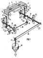
- Figure 1 is a schematic perspective view of the device according to the invention, in the case of measuring the creep in one direction.
- Figure 2 is a schematic perspective view of the device in the case of measuring the creep in two perpendicular directions.
- Figures 3 and 4 show partial schematic views of the locking member of the device according to the invention, respectively in the operational position and in the retracted position.
- FIG. 1 represents a device able to allow the creep of a sample from a textile material, for example from a tarpaulin, to be measured. This measurement is carried out in a single direction, for example according to the chain.
- a strip (1) of this material is placed flat on the base (2).
- the latter is metallic and can advantageously be heated, in particular when it is desired to carry out accelerated creep measurements, thereby allowing an acceleration of the aging of the material, and therefore of observing its resistance over time.
- the strip (1) is held in place on the base (2) by means of a transparent plate, for example made of plastic, of the same surface as the base (2) and fixed on the latter to the screw means, the fixing holes (3) of which are shown.
- a transparent plate for example made of plastic
- the two free ends (6) and (7) of the strip (1) are returned on return cylinders (4) and (5) parallel and free in rotation. These two free ends (6) and (7) are respectively fixed to two self-locking and self-clamping jaws (8) and (9), commonly used for safety straps in the automotive and automotive fields. aviation.
- Each of the two jaws (8) and (9) is integral with a bracket (14) and (15) and this by means of a link (12) and (13).
- These links are advantageously constituted by a screw tensioner, capable of ensuring a slight pre-traction before loading, and allowing a more precise positioning of the strip (1) on the base (2).
- the other end of the screw tensioners (12) and (13) is fixed by means of a yoke, respectively (16) and (17) to a bracket (14) and (15).
- This yoke is also pendular and is fixed to the brackets (14) and (15) by means of a ball joint, in order to limit any friction as much as possible.
- the two brackets (14) and (15) are respectively secured to a primary (21) and secondary (22) shaft, parallel to each other. These two shafts (21) and (22) are fixed to the frame carrying the entire device by means of ball bearing bearings (23) and (24).
- the two brackets (14) and (15) are located in the same plane, and homothetic to each other in this plane. In fact, the two brackets (14) and (15) are identical.
- the two brackets (14) and (15) are integral with one another by means of a tie rod (18).
- This tie rod is fixed to the two brackets (14) and (15) by means of yokes (19) and (20) also mounted on ball joints in order to limit the friction forces as much as possible.
- the primary shaft (21) is actuated by means of a lever arm (25) whose direction is parallel to the direction of the line defined by the respective center of the primary and secondary trees (21) and (22) and l 'pivot axis respectively of the ball joints of the yokes (16) and (17).
- the free end of the lever arm (25) comprises a weight carrier (26) mounted pendulumly by means of a yoke (17) and a ball joint.
- This weight carrier is intended to receive masses (28) of known size.
- the creep is then determined by measuring the difference separating two marks previously drawn in the vicinity of the center of the strip on the base (2).
- This difference can be measured manually by means of graduated rulers but advantageously by means of photometers not shown, mounted above the base.
- the present invention can also be applied to measure the mechanical properties of a sample in two directions. This measurement can be carried out in particular in two perpendicular directions, for example along the weft and the warp of a fabric.
- the device comprises two structures similar to those described above, mounted perpendicularly to each other. These two structures are perfectly independent of each other.
- the device is provided with a locking member. (29), acting on a tab (30) welded to each of the secondary shafts (22).
- This locking member (29) is integral with a handle (31), which is substantially perpendicular to it.
- This handle (31) is articulated around an axis (32) formed on the frame of the device, in order to allow its rotation and thus, the retraction of the locking member and therefore the release of the tab (30).
- This release also allows the rotation of the secondary axes (22), and consequently that of the primary axes (21), taking into account their dependence by means of the tie rod (18).
- each device comprises a locking member (29) as well as the elements with which they cooperate.
- the two handles (31) of the locking members are located in the vicinity of each other.
- the device thus described makes it possible to carry out measurements of mechanical properties, in particular creep, and especially mono-axial and bi-axial creep, and of tensile toughness for samples of material, without requiring material of high cost.
- the implementation of such equipment is easy and does not require qualified personnel.
Landscapes
- General Health & Medical Sciences (AREA)
- Health & Medical Sciences (AREA)
- Life Sciences & Earth Sciences (AREA)
- Chemical & Material Sciences (AREA)
- Analytical Chemistry (AREA)
- Biochemistry (AREA)
- Physics & Mathematics (AREA)
- General Physics & Mathematics (AREA)
- Immunology (AREA)
- Pathology (AREA)
- Investigating Strength Of Materials By Application Of Mechanical Stress (AREA)
- Treatment Of Fiber Materials (AREA)
- Sampling And Sample Adjustment (AREA)
Claims (9)
- Vorrichtung zum Messen der mechanischen Eigenschaften einer Probe in Form eines Streifens (1), der an seinen Enden (6, 7) zwischen zwei Klemmen (8, 9) befestigt ist und auf einem Sockel (2) ruht, weist auf:- zwei zueinander parallele Umlenkzylinder (4, 5), die beiderseits des Sockels (2) angeordnet sind und über die der Streifen (1) umgelegt ist, auf den über die Klemmen (8, 9) auf die beiden freien Enden (6, 7) eine Zugbeanspruchung gleicher Stärke ausgeübt ist,- zwei bewegliche Stangen (12, 13), die jeweils auf der einen Seite an den Klemmen (8, 9) und an der anderen Seite an zwei Winkelstücken (14, 15) über zwei bewegliche Gabelstücke (16, 17) befestigt sind, wobei die beiden Winkelstücke (14, 15) in einer Ebene liegen und fest mit zwei, jeweils einer ersten und zweiten, parallelen Achse verbunden sind und untereinander über eine Zugstange verbunden sind, dessen zwei äußere Enden über Gabelstücke an den Winkelstücken (14, 15) angebracht sind, wobei die beiden Winkelstücke (14, 15) in der sie aufweisenden Ebene zueinander ähnlich sind,- einen an der ersten Achse (21) fest angebrachten Hebelarm, dessen Richtung immer parallel zu der Richtung ist, die durch die jeweils durch die Drehachse der ersten Achse (21) und der zweiten Achse (22) und die Drehachse der die Stangen (12, 13) an den Winkelstücken 14, 15) befestigenden Gabelstücke verlaufende Gerade festgelegt ist und- einen Gewichtsträger, der an dem freien Ende des Hebelarmes (25) befestigt ist und der zur Aufnahme von Massenstücken bekannter Größe dient.
- Vorrichtung nach Anspruch 1, dadurch gekennzeichnet, daß die erste Achse (21) und zweite Achse (22) in Kugellager (23, 24) befestigt sind.
- Vorrichtung nach einem der Ansprüche 1 und 2, dadurch gekennzeichnet, daß die Verbindung der Stangen (12, 13) mit den Klemmen (8, 9) mittels Gelenke ausgeführt ist.
- Vorrichtung nach einem der Ansprüche 1 bis 3, dadurch gekennzeichnet, daß die Gabelstücke an Lager (23, 24) befestigt sind.
- Vorrichtung nach einem der Ansprüche 1 bis 4, dadurch gekennzeichnet, daß der Sockel (2) heizbar ist.
- Vorrichtung nach einem der Ansprüche 1 bis 5, dadurch gekennzeichnet, daß die Klemmen (8, 9) selbstverriegelnd und selbstverklemmend sind.
- Vorrichtung nach einem der Ansprüche 1 bis 6, dadurch gekennzeichnet, daß sie ein über dem Sockel (2) angeordnetes Photometer oder ein Bildverarbeitungssystem aufweist, das das Messen der mechanischen Eigenschaften und insbesondere des Dehnverhaltens erlaubt.
- Vorrichtung zum Messen der mechanischen Eigenschaften einer Probe in Form eines Streifens in zwei zueinander rechtwinkligen Richtungen, dadurch gekennzeichnet, daß die Zugbeanspruchung auf jeden der zueinander rechtwinkligen Streifen über zwei ähnliche, voneinander unabhängige, in den Ansprüchen 1 bis 7 beschriebenen Vorrichtungen ausgeübt ist.
- Vorrichtung nach Anspruch 8, dadurch gekennzeichnet, daß die Hebelarme (25) in oberer Position mittels eine einen gelenkigen Griff (31) aufweisende Verriegelungseinheit (29) verriegelbar sind, wobei diese Einheit (29) mit einer an den zweiten Achsen (22) fest angebrachten Klaue (30) zusammenarbeiten.
Priority Applications (1)
| Application Number | Priority Date | Filing Date | Title |
|---|---|---|---|
| AT90420488T ATE89921T1 (de) | 1989-11-17 | 1990-11-13 | Vorrichtung zur messung von mechanischen eigenschaften einer probe, bzw. textilien. |
Applications Claiming Priority (2)
| Application Number | Priority Date | Filing Date | Title |
|---|---|---|---|
| FR8915379A FR2654833B1 (fr) | 1989-11-17 | 1989-11-17 | Dispositif pour mesurer les proprietes mecaniques d'un echantillon notamment textile. |
| FR8915379 | 1989-11-17 |
Publications (2)
| Publication Number | Publication Date |
|---|---|
| EP0429376A1 EP0429376A1 (de) | 1991-05-29 |
| EP0429376B1 true EP0429376B1 (de) | 1993-05-26 |
Family
ID=9387688
Family Applications (1)
| Application Number | Title | Priority Date | Filing Date |
|---|---|---|---|
| EP90420488A Expired - Lifetime EP0429376B1 (de) | 1989-11-17 | 1990-11-13 | Vorrichtung zur Messung von mechanischen Eigenschaften einer Probe, bzw. Textilien |
Country Status (4)
| Country | Link |
|---|---|
| EP (1) | EP0429376B1 (de) |
| AT (1) | ATE89921T1 (de) |
| DE (1) | DE69001746T2 (de) |
| FR (1) | FR2654833B1 (de) |
Families Citing this family (12)
| Publication number | Priority date | Publication date | Assignee | Title |
|---|---|---|---|---|
| DE59803173D1 (de) * | 1997-09-02 | 2002-04-04 | Chemiefaser Lenzing Ag | Verfahren zur Bestimmung der Festigkeitseigenschaften von langgestrecktem, textilem Prüfgut und Vorrichtung zur Durchführung des Verfahrens |
| GB0517659D0 (en) | 2005-08-31 | 2005-10-05 | Watkins Penelope A | Tensile tester |
| CN1869638B (zh) * | 2006-06-09 | 2010-05-12 | 周建青 | 电子式织物强力测试仪 |
| CZ301314B6 (cs) * | 2008-11-14 | 2010-01-13 | Technická univerzita v Liberci | Zpusob zjištování mechanických vlastností plošných textilií a zarízení k jeho provádení |
| CN101694444B (zh) * | 2009-10-22 | 2011-05-25 | 国际竹藤网络中心 | 纤维织物及纺织结构复合材料力学性能检测方法 |
| CN102998253A (zh) * | 2012-12-12 | 2013-03-27 | 江南大学 | 一种织物折皱回复角动态测量和表征方法 |
| DE102014110856B4 (de) | 2014-07-31 | 2016-04-14 | Schott Ag | Verfahren und Vorrichtung zur Bestimmung der Kantenfestigkeit von scheibenförmigen Elementen aus sprödbrüchigem Material |
| DE102014110855B4 (de) | 2014-07-31 | 2017-08-03 | Schott Ag | Verfahren und Vorrichtung zur Bestimmung der Bruchfestigkeit der Ränder dünner Bahnen sprödbrüchigen Materials |
| CN105651616B (zh) * | 2016-03-30 | 2018-11-30 | 绍兴柯桥富荣纺织有限公司 | 一种拖钩强度试验装置 |
| CN109738188B (zh) * | 2019-01-16 | 2024-02-06 | 西南科技大学 | 评估轴承保持架耐磨性的装置及方法 |
| CN110398411B (zh) * | 2019-07-30 | 2022-01-25 | 威海迪尚华绮毛纺织有限公司 | 纺织品拉力强度检测设备 |
| CN120026448B (zh) * | 2025-02-25 | 2025-09-09 | 众望布艺股份有限公司 | 一种抗菌面料的加工制作方法 |
Family Cites Families (4)
| Publication number | Priority date | Publication date | Assignee | Title |
|---|---|---|---|---|
| FR533535A (fr) * | 1920-02-09 | 1922-03-04 | Goodrich Co B F | Machine à essayer les toiles tissées |
| US2568731A (en) * | 1949-01-07 | 1951-09-25 | Arnold M Hansen | Instrument for measuring elasticity and elastic recovery of textile fabric |
| US2850895A (en) * | 1956-03-12 | 1958-09-09 | Inst Textile Tech | Gripping means for fabric test specimens |
| GB2029971A (en) * | 1978-05-25 | 1980-03-26 | Cotton Silk & Man Made Fibres | Improvements in or relating to the testing of woven fabric |
-
1989
- 1989-11-17 FR FR8915379A patent/FR2654833B1/fr not_active Expired - Fee Related
-
1990
- 1990-11-13 EP EP90420488A patent/EP0429376B1/de not_active Expired - Lifetime
- 1990-11-13 AT AT90420488T patent/ATE89921T1/de not_active IP Right Cessation
- 1990-11-13 DE DE9090420488T patent/DE69001746T2/de not_active Expired - Fee Related
Also Published As
| Publication number | Publication date |
|---|---|
| ATE89921T1 (de) | 1993-06-15 |
| FR2654833B1 (fr) | 1992-01-31 |
| FR2654833A1 (fr) | 1991-05-24 |
| EP0429376A1 (de) | 1991-05-29 |
| DE69001746D1 (de) | 1993-07-01 |
| DE69001746T2 (de) | 1993-09-02 |
Similar Documents
| Publication | Publication Date | Title |
|---|---|---|
| EP0429376B1 (de) | Vorrichtung zur Messung von mechanischen Eigenschaften einer Probe, bzw. Textilien | |
| FR2679031A1 (fr) | Machine d'equilibrage pour des roues de vehicules automobiles. | |
| FR2643712A1 (fr) | Procede de mesure du couple transmis a la roue motrice d'un cycle ou vehicule similaire et dispositif pour la mise en oeuvre de ce procede | |
| EP0579961B1 (de) | Messapparat zur Messung linearer Grössen | |
| FR2470372A1 (fr) | Dispositif pour evaluer la force d'un coup au golf | |
| EP0060766A1 (de) | Kraftsensoreinrichtung für Messgerät | |
| FR2529345A1 (fr) | Dispositif sur lequel peut pivoter un pendule sensible a une force dans un accelerometre comportant un bati de support | |
| FR3093175A1 (fr) | Systeme de mesure d’une deformation de surface en flexion d’un materiau | |
| FR2579327A1 (fr) | Dispositif perfectionne d'essais de traction biaxiale | |
| EP1261463A1 (de) | Servogesteuerte lasthandhabungsvorrichtung | |
| FR2475727A1 (fr) | Dispositif de controle d'appareils dynamometriques | |
| FR2587110A1 (fr) | Equilibreuse de roues et notamment de roues de vehicule automobile | |
| EP0395517B1 (de) | Festigkeitsmessgerät | |
| EP1743154A1 (de) | Vorrichtung zur steuerung der sicherheitsspannung von länglichen gegenständen, insbesondere sicherheitsgurten und steuerverfahren | |
| FR2616901A1 (fr) | Extensometre multi-axial, en particulier extensometre tri-axial | |
| FR2735235A1 (fr) | Appareil pour effectuer des essais mecaniques de flexion sur une piece | |
| FR2612869A1 (fr) | Pedale pour cycles comportant un moyen de fixation rapide d'une chaussure | |
| FR2569272A1 (fr) | Dispositif pour mesurer la tension d'une bande | |
| EP0346318A1 (de) | Vorrichtung zur Feststellung einer auf ein fadenförmiges Teil einer Last ausgeübten Kraft | |
| FR2619214A1 (fr) | Appareil pour la detection du balourd d'une roue d'automobile en vue de l'equilibrage de celle-ci. | |
| FR2528575A1 (fr) | Capteur de force, notamment pour le pesage | |
| FR2528977A1 (fr) | Dispositif pour l'etalonnage et la verification des couplemetres | |
| FR2651884A1 (fr) | Appareil pour la detection du balourd d'une roue d'automobile en vue de l'equilibrage de celle-ci. | |
| FR2595139A1 (fr) | Machine d'essais de fatigue en flexion-torsion, pour eprouvettes notamment en materiau composite | |
| EP0008983A2 (de) | Waage mit einem deutlichen Kippunkt für kontinuierliche Gewichtssortierung |
Legal Events
| Date | Code | Title | Description |
|---|---|---|---|
| PUAI | Public reference made under article 153(3) epc to a published international application that has entered the european phase |
Free format text: ORIGINAL CODE: 0009012 |
|
| AK | Designated contracting states |
Kind code of ref document: A1 Designated state(s): AT BE CH DE DK ES GB IT LI NL SE |
|
| 17P | Request for examination filed |
Effective date: 19910731 |
|
| 17Q | First examination report despatched |
Effective date: 19921111 |
|
| GRAA | (expected) grant |
Free format text: ORIGINAL CODE: 0009210 |
|
| AK | Designated contracting states |
Kind code of ref document: B1 Designated state(s): AT BE CH DE DK ES GB IT LI NL SE |
|
| PG25 | Lapsed in a contracting state [announced via postgrant information from national office to epo] |
Ref country code: IT Free format text: LAPSE BECAUSE OF FAILURE TO SUBMIT A TRANSLATION OF THE DESCRIPTION OR TO PAY THE FEE WITHIN THE PRE;WARNING: LAPSES OF ITALIAN PATENTS WITH EFFECTIVE DATE BEFORE 2007 MAY HAVE OCCURRED AT ANY TIME BEFORE 2007. THE CORRECT EFFECTIVE DATE MAY BE DIFFERENT FROM THE ONE RECORDED.SCRIBED TIME-LIMIT Effective date: 19930526 Ref country code: SE Effective date: 19930526 Ref country code: NL Effective date: 19930526 Ref country code: DK Effective date: 19930526 Ref country code: ES Free format text: THE PATENT HAS BEEN ANNULLED BY A DECISION OF A NATIONAL AUTHORITY Effective date: 19930526 Ref country code: AT Effective date: 19930526 Ref country code: GB Effective date: 19930526 |
|
| REF | Corresponds to: |
Ref document number: 89921 Country of ref document: AT Date of ref document: 19930615 Kind code of ref document: T |
|
| REF | Corresponds to: |
Ref document number: 69001746 Country of ref document: DE Date of ref document: 19930701 |
|
| K2C2 | Correction of patent specification (partial reprint) published |
Effective date: 19930526 |
|
| NLV1 | Nl: lapsed or annulled due to failure to fulfill the requirements of art. 29p and 29m of the patents act | ||
| PG25 | Lapsed in a contracting state [announced via postgrant information from national office to epo] |
Ref country code: LI Effective date: 19931130 Ref country code: CH Effective date: 19931130 Ref country code: BE Effective date: 19931130 |
|
| GBV | Gb: ep patent (uk) treated as always having been void in accordance with gb section 77(7)/1977 [no translation filed] |
Effective date: 19930526 |
|
| PLBE | No opposition filed within time limit |
Free format text: ORIGINAL CODE: 0009261 |
|
| STAA | Information on the status of an ep patent application or granted ep patent |
Free format text: STATUS: NO OPPOSITION FILED WITHIN TIME LIMIT |
|
| 26N | No opposition filed | ||
| BERE | Be: lapsed |
Owner name: S.A. TISSAGE ET ENDUCTION SERGE FERRARI Effective date: 19931130 |
|
| REG | Reference to a national code |
Ref country code: CH Ref legal event code: PL |
|
| PGFP | Annual fee paid to national office [announced via postgrant information from national office to epo] |
Ref country code: DE Payment date: 19961123 Year of fee payment: 7 |
|
| PG25 | Lapsed in a contracting state [announced via postgrant information from national office to epo] |
Ref country code: DE Free format text: LAPSE BECAUSE OF NON-PAYMENT OF DUE FEES Effective date: 19980801 |