EP0429376B1 - Apparatus for measuring the mechanical properties of a sample, especially textile - Google Patents
Apparatus for measuring the mechanical properties of a sample, especially textile Download PDFInfo
- Publication number
- EP0429376B1 EP0429376B1 EP90420488A EP90420488A EP0429376B1 EP 0429376 B1 EP0429376 B1 EP 0429376B1 EP 90420488 A EP90420488 A EP 90420488A EP 90420488 A EP90420488 A EP 90420488A EP 0429376 B1 EP0429376 B1 EP 0429376B1
- Authority
- EP
- European Patent Office
- Prior art keywords
- jaws
- brackets
- mechanical properties
- fixed
- sample
- Prior art date
- Legal status (The legal status is an assumption and is not a legal conclusion. Google has not performed a legal analysis and makes no representation as to the accuracy of the status listed.)
- Expired - Lifetime
Links
Images


Classifications
-
- G—PHYSICS
- G01—MEASURING; TESTING
- G01N—INVESTIGATING OR ANALYSING MATERIALS BY DETERMINING THEIR CHEMICAL OR PHYSICAL PROPERTIES
- G01N3/00—Investigating strength properties of solid materials by application of mechanical stress
- G01N3/08—Investigating strength properties of solid materials by application of mechanical stress by applying steady tensile or compressive forces
- G01N3/14—Investigating strength properties of solid materials by application of mechanical stress by applying steady tensile or compressive forces generated by dead weight, e.g. pendulum; generated by springs tension
-
- G—PHYSICS
- G01—MEASURING; TESTING
- G01N—INVESTIGATING OR ANALYSING MATERIALS BY DETERMINING THEIR CHEMICAL OR PHYSICAL PROPERTIES
- G01N3/00—Investigating strength properties of solid materials by application of mechanical stress
- G01N3/02—Details
- G01N3/04—Chucks
-
- G—PHYSICS
- G01—MEASURING; TESTING
- G01N—INVESTIGATING OR ANALYSING MATERIALS BY DETERMINING THEIR CHEMICAL OR PHYSICAL PROPERTIES
- G01N2203/00—Investigating strength properties of solid materials by application of mechanical stress
- G01N2203/003—Generation of the force
- G01N2203/0032—Generation of the force using mechanical means
- G01N2203/0033—Weight
-
- G—PHYSICS
- G01—MEASURING; TESTING
- G01N—INVESTIGATING OR ANALYSING MATERIALS BY DETERMINING THEIR CHEMICAL OR PHYSICAL PROPERTIES
- G01N2203/00—Investigating strength properties of solid materials by application of mechanical stress
- G01N2203/0058—Kind of property studied
- G01N2203/0069—Fatigue, creep, strain-stress relations or elastic constants
- G01N2203/0071—Creep
-
- G—PHYSICS
- G01—MEASURING; TESTING
- G01N—INVESTIGATING OR ANALYSING MATERIALS BY DETERMINING THEIR CHEMICAL OR PHYSICAL PROPERTIES
- G01N2203/00—Investigating strength properties of solid materials by application of mechanical stress
- G01N2203/02—Details not specific for a particular testing method
- G01N2203/026—Specifications of the specimen
- G01N2203/0262—Shape of the specimen
- G01N2203/0278—Thin specimens
- G01N2203/0282—Two dimensional, e.g. tapes, webs, sheets, strips, disks or membranes
-
- G—PHYSICS
- G01—MEASURING; TESTING
- G01N—INVESTIGATING OR ANALYSING MATERIALS BY DETERMINING THEIR CHEMICAL OR PHYSICAL PROPERTIES
- G01N33/00—Investigating or analysing materials by specific methods not covered by groups G01N1/00 - G01N31/00
- G01N33/36—Textiles
Landscapes
- Physics & Mathematics (AREA)
- Health & Medical Sciences (AREA)
- Life Sciences & Earth Sciences (AREA)
- Chemical & Material Sciences (AREA)
- Analytical Chemistry (AREA)
- Biochemistry (AREA)
- General Health & Medical Sciences (AREA)
- General Physics & Mathematics (AREA)
- Immunology (AREA)
- Pathology (AREA)
- Investigating Strength Of Materials By Application Of Mechanical Stress (AREA)
- Treatment Of Fiber Materials (AREA)
- Sampling And Sample Adjustment (AREA)
Abstract
Description
L'invention concerne un dispositif apte à permettre la mesure des propriétés mécaniques d'un échantillon et notamment d'un échantillon textile.The invention relates to a device capable of allowing the measurement of the mechanical properties of a sample and in particular of a textile sample.
Par "propriétés mécaniques", on entend principalement, mais non limitativement, le fluage et la ténacité en traction.By "mechanical properties" is meant mainly, but not limited to, creep and tensile toughness.
L'invention se rapporte plus particulièrement à un dispositif du type en question, apte à mesurer ces propriétés mécaniques selon une ou deux directions bien déterminées.The invention relates more particularly to a device of the type in question, capable of measuring these mechanical properties in one or two well-defined directions.
Jusqu'à présent, lorsque l'on désire procéder à la mesure du fluage d'un matériau, selon l'une de ses directions principales, on utilise un dynamomètre dont les deux mâchoires enserrent les deux extrémités d'une bande découpée dans ce matériau. La bande est découpée dans la direction selon laquelle on désire procéder à la mesure. De fait, si l'on désire procéder à la mesure du fluage selon deux directions bien définies, notamment perpendiculaires, par exemple selon la trame et selon la chaine s'il s'agit d'un matériau textile, on doit effectuer deux mesures consécutives ou utiliser un dynamomètre bi-axial. Ce type de dispositif est particulièrement coûteux car un tel appareil est en fait constitué de deux dynamomètres. Il s'avère de plus relativement long et difficile à mettre en oeuvre, donc il est impensable de pouvoir diffuser en masse un tel dispositif. Les documents US - A - 2 850 895 et GB - A - 2 029 971 décrivent des dispositifs permettant de mesurer les propriétés mécaniques de textiles dans lesquels les échantillons sont maintenus par des mâchoires. Dans le document US - A - 2 568 731, la traction sur les fils de l'échantillon textile est exercée, selon deux directions perpendiculaires, à l'aide de poids.Up to now, when it is desired to measure the creep of a material, in one of its main directions, a dynamometer has been used, the two jaws of which enclose the two ends of a strip cut from this material . The strip is cut in the direction in which one wishes to carry out the measurement. In fact, if one wishes to measure the creep in two well-defined directions, in particular perpendicular, for example along the weft and along the warp if it is a textile material, two consecutive measurements must be made. or use a bi-axial dynamometer. This type of device is particularly expensive because such a device is in fact made up of two dynamometers. It also turns out to be relatively long and difficult to implement, so it is unthinkable to be able to distribute such a device in mass. Documents US-A-2,850,895 and GB-A-2,029,971 describe devices for measuring the mechanical properties of textiles in which the samples are held by jaws. In document US-A-2,568,731, the traction on the threads of the textile sample is exerted, in two perpendicular directions, using weights.
L'invention pallie ces inconvénients. Elle propose un dispositif apte à mesurer les propriétés mécaniques, notamment le fluage, d'un matériau se présentant sous forme de bande, peu coûteux à réaliser, facile à mettre en oeuvre et aussi fiable qu'un dynamomètre.The invention overcomes these drawbacks. It offers a device capable of measuring the mechanical properties, especially creep, of a material in the form of a strip, inexpensive to produce, easy to use and as reliable as a dynamometer.
Ce dispositif, pour mesurer les propriétés mécaniques d'un échantillon sous forme de bande fixée à ses extrémités entre deux mâchoires,
- un socle sur lequel repose ladite bande et comprenant
- deux cylindres de renvoi parallèles, disposés de part et d'autre du socle et sur lequel est renvoyé ladite bande, sur les deux extrémités libres de laquelle s'exerce une traction de même intensité par l'intermédiaire des mâchoires ;
- deux biellettes pendulaires fixées respectivement d'une part aux mâchoires, et d'autre part à deux équerres par l'intermédiaire de deux chapes pendulaires, les deux équerres étant contenues dans le même plan, et solidaires de deux arbres parallèles, respectivement primaire et secondaire, et solidarisées entre elles au moyen d'un tirant dont les deux extrémités sont fixées aux équerres par l'intermédiaire de chapes, les deux équerres étant homothétiques l'une de l'autre dans le plan les contenant ;
- un bras de levier, solidaire de l'arbre primaire, dont la direction est toujours parallèle à la direction définie par la droite passant par respectivement l'axe de rotation de l'arbre primaire et de l'arbre secondaire et, l'axe de pivotement des chapes solidarisant les biellettes aux équerres ;
- un porte-poids, fixé à l'extrémité libre du bras de levier, et destiné à recevoir des masses de grandeur connues.
- a base on which said strip rests and comprising
- two parallel return cylinders, arranged on either side of the base and on which said strip is returned, on the two free ends of which a traction of the same intensity is exerted via the jaws;
- two pendulum rods fixed respectively on the one hand to the jaws, and on the other hand to two brackets by means of two pendulum yokes, the two brackets being contained in the same plane, and integral with two parallel shafts, respectively primary and secondary , and joined together by means of a tie rod, the two ends of which are fixed to the brackets by means of yokes, the two brackets being homothetic to one another in the plane containing them;
- a lever arm, integral with the primary shaft, the direction of which is always parallel to the direction defined by the straight line passing respectively through the axis of rotation of the primary shaft and of the secondary shaft and, the axis of pivoting of the yokes securing the rods to the brackets;
- a weight carrier, fixed to the free end of the lever arm, and intended to receive masses of known size.
En d'autres termes, la présente invention se caractérise en ce que l'on associe entre eux des organes et éléments connus selon une architecture particulière, afin de générer au niveau des deux extrémités libres d'un échantillon sous forme de bande, une traction modulable de même intensité, ou un phénomène de fluage dont on peut alors mesurer les effets dans le temps.In other words, the present invention is characterized in that known organs and elements are combined together according to a particular architecture, in order to generate, at the two free ends of a sample in the form of a strip, a traction modular of the same intensity, or a creep phenomenon whose effects can then be measured over time.
Avantageusement en pratique :
- les arbres primaires et secondaires sont montés sur des paliers munis de roulements à bille ;
- la liaison des biellettes sur les mâchoires s'effectue au moyen de rotules ;
- les chapes sont fixées sur des roulements ;
- le socle recevant l'échantillon est chauffant ;
- la mesure des propriétés mécaniques, et notamment de fluage est effectuée au moyen d'un photomètre, ou tout système de traitement d'images, situé au-dessus du socle;
- les propriétés mécaniques sont mesurées selon deux directions perpendiculaires, la traction sur chacune des deux bandes perpendiculaires issues du matériau étant effectuée au moyen de deux dispositifs similaires à celui décrit précédemment et indépendant l'un de l'autre;
- les bras de levier sont verrouillés en position haute de manière indépendante au moyen d'un crochet muni d'une poignée agissant au niveau des arbres secondaires.
- the primary and secondary shafts are mounted on bearings provided with ball bearings;
- the connecting rods on the jaws is made by means of ball joints;
- the yokes are fixed on bearings;
- the base receiving the sample is heated;
- the measurement of the mechanical properties, and in particular of creep, is carried out by means of a photometer, or any image processing system, located above the base;
- the mechanical properties are measured in two perpendicular directions, the traction on each of the two perpendicular strips coming from the material being carried out by means of two devices similar to that described above and independent of each other;
- the lever arms are locked in the high position independently by means of a hook provided with a handle acting at the level of the secondary shafts.
La manière dont l'invention peut être réalisée et les avantages qui en découlent, ressortiront mieux de l'exemple de réalisation donné à titre indicatif et non limitatif à l'appui des figures annexées.The manner in which the invention can be implemented and the advantages which ensue therefrom will emerge more clearly from the exemplary embodiment given by way of nonlimiting indication in support of the attached figures.
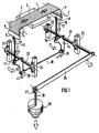
La figure 1 est une vue schématique en perspective du dispositif conforme à l'invention, dans le cas de la mesure du fluage selon une seule direction.Figure 1 is a schematic perspective view of the device according to the invention, in the case of measuring the creep in one direction.
La figure 2 est une vue schématique en perspective du dispositif dans le cas de la mesure du fluage selon deux directions perpendiculaires.Figure 2 is a schematic perspective view of the device in the case of measuring the creep in two perpendicular directions.
Les figures 3 et 4 représentent des vues schématiques partielles de l'organe de verrouillage du dispositif conforme à l'invention, respectivement en position opérationnelle et en position escamotée.Figures 3 and 4 show partial schematic views of the locking member of the device according to the invention, respectively in the operational position and in the retracted position.
L'exemple décrit dans la figure 1 représente un dispositif apte à permettre la mesure du fluage d'un échantillon issu d'un matériau textile, par exemple d'une bache. Cette mesure s'effectue selon une seule direction, par exemple selon la chaine.The example described in FIG. 1 represents a device able to allow the creep of a sample from a textile material, for example from a tarpaulin, to be measured. This measurement is carried out in a single direction, for example according to the chain.
Une bande (1) de ce matériau est mise en place à plat sur le socle (2). Ce dernier est métallique et peut être avantageusement chauffant, notamment lorsque l'on désire effectuer des mesures de fluage en accéléré, permettant de la sorte une accélération du vieillissement du matériau, et donc d'observer sa tenue dans le temps.A strip (1) of this material is placed flat on the base (2). The latter is metallic and can advantageously be heated, in particular when it is desired to carry out accelerated creep measurements, thereby allowing an acceleration of the aging of the material, and therefore of observing its resistance over time.
Avantageusement mais non nécessairement, la bande (1) est maintenue en place sur le socle (2) au moyen d'une plaque transparente, par exemple réalisée en matière plastique, de même surface que le socle (2) et fixée sur ce dernier au moyen de vis dont on a représenté les orifices de fixation (3).Advantageously but not necessarily, the strip (1) is held in place on the base (2) by means of a transparent plate, for example made of plastic, of the same surface as the base (2) and fixed on the latter to the screw means, the fixing holes (3) of which are shown.
Les deux extrémités libres (6) et (7) de la bande (1) sont renvoyées sur des cylindres de renvoi (4) et (5) parallèles et libres en rotation. Ces deux extrémités libres (6) et (7) sont respectivement fixées à deux mâchoires (8) et (9) auto-bloquantes et auto-serrantes, couramment utilisées pour les sangles de sécurité dans le domaine de l'automobile et de l'aviation.The two free ends (6) and (7) of the strip (1) are returned on return cylinders (4) and (5) parallel and free in rotation. These two free ends (6) and (7) are respectively fixed to two self-locking and self-clamping jaws (8) and (9), commonly used for safety straps in the automotive and automotive fields. aviation.
Chacune des deux mâchoires (8) et (9) est solidaire d'une équerre (14) et (15) et ce par l'intermédiaire d'une biellette (12) et (13). Ces biellettes sont avantageusement constituées d'un tendeur à vis, apte à assurer une légère pré-traction avant la mise en chargement, et à permettre une mise en place plus précise de la bande (1) sur le socle (2).Each of the two jaws (8) and (9) is integral with a bracket (14) and (15) and this by means of a link (12) and (13). These links are advantageously constituted by a screw tensioner, capable of ensuring a slight pre-traction before loading, and allowing a more precise positioning of the strip (1) on the base (2).
Ces tendeurs à vis (12) et (13) sont fixés aux mâchoires (8) et (9) au moyen de rotules (10) et (11) pendulaires. De la sorte, la traction exercée sur les deux extrémités (6) et (7) de la bande (1) d'un matériau dont on désire mesurer les propriétés mécaniques et notamment le fluage, est indépendante du positionnement de ladite bande dans les mâchoires. De plus, cette rotule permet le débattement pendulaire de la bielle qui dans le cas d'espèces est limitée à quelques degrés.These screw tensioners (12) and (13) are fixed to the jaws (8) and (9) by means of ball joints (10) and (11) pendulum. In this way, the traction exerted on the two ends (6) and (7) of the strip (1) of a material whose mechanical properties and in particular creep is to be measured, is independent of the positioning of said strip in the jaws . In addition, this ball joint allows the pendulum movement of the connecting rod which in the case of species is limited to a few degrees.
L'autre extrémité des tendeurs à vis (12) et (13) est fixée par l'intermédiaire d'une chape, respectivement (16) et (17) à une équerre (14) et (15). Cette chape est également pendulaire et est fixée sur les équerres (14) et (15) par l'intermédiaire d'une rotule, afin de limiter au maximum les frottements éventuels.The other end of the screw tensioners (12) and (13) is fixed by means of a yoke, respectively (16) and (17) to a bracket (14) and (15). This yoke is also pendular and is fixed to the brackets (14) and (15) by means of a ball joint, in order to limit any friction as much as possible.
Les deux équerres (14) et (15) sont respectivement solidarisées à un arbre primaire (21) et secondaire (22), parallèles entre eux. Ces deux arbres (21) et (22) sont fixés au bâti portant l'ensemble du dispositif au moyen de paliers à roulements à billes (23) et (24).The two brackets (14) and (15) are respectively secured to a primary (21) and secondary (22) shaft, parallel to each other. These two shafts (21) and (22) are fixed to the frame carrying the entire device by means of ball bearing bearings (23) and (24).
Selon une caractéristique importante de l'invention, les deux équerres (14) et (15) sont situées dans un même plan, et homothétique l'une de l'autre dans ce plan. De fait, les deux équerres (14) et (15) sont identiques.According to an important characteristic of the invention, the two brackets (14) and (15) are located in the same plane, and homothetic to each other in this plane. In fact, the two brackets (14) and (15) are identical.
Selon une autre caractéristique de l'invention, les deux équerres (14) et (15) sont solidaires l'une de l'autre au moyen d'un tirant (18). Ce tirant est fixé aux deux équerres (14) et (15) au moyen de chapes (19) et (20) également montées sur rotules afin de limiter au maximum les forces de frottement. L'arbre primaire (21) est actionné au moyen d'un bras de levier (25) dont la direction est parallèle à la direction de la droite définie par le centre respectif des arbres primaire et secondaire (21) et (22) et l'axe de pivotement respectivement des rotules des chapes (16) et (17).According to another characteristic of the invention, the two brackets (14) and (15) are integral with one another by means of a tie rod (18). This tie rod is fixed to the two brackets (14) and (15) by means of yokes (19) and (20) also mounted on ball joints in order to limit the friction forces as much as possible. The primary shaft (21) is actuated by means of a lever arm (25) whose direction is parallel to the direction of the line defined by the respective center of the primary and secondary trees (21) and (22) and l 'pivot axis respectively of the ball joints of the yokes (16) and (17).
L'extrémité libre du bras de levier (25) comporte un porte-poids (26) monté pendulairement par l'intermédiaire d'une chape (17) et d'une rotule. Ce porte-poids est destiné à recevoir des masses (28) de grandeur connue.The free end of the lever arm (25) comprises a weight carrier (26) mounted pendulumly by means of a yoke (17) and a ball joint. This weight carrier is intended to receive masses (28) of known size.
Compte tenu de la structure de ce dispositif, lorsque l'on applique une masse sur le porte-poids (26), il en résulte compte tenu de la gravité, une rotation du bras de levier (25) dans le sens inverse des aiguilles d'une montre, tel que représenté dans la figure 1, provoquant une rotation de l'arbre primaire (21) dans le même sens. Dans l'exemple décrit, le rapport entre la force de traction sur les extrémités (6) et (7) de la bande (1) et l'intensité de la force créée par les masses (28) est égal à 5. Par exemple, une masse (28) de 60 kg génère une force de traction de 3000 Newtons. Il provoque d'une part la rotation de l'équerre (14) également dans le sens inverse des aiguilles d'une montre ayant pour effet, d'une part d'imprimer une traction sur l'extrémité (7) de la bande (1) et d'autre part d'induire la rotation de l'équerre (15), également en sens inverse des aiguilles d'une montre, cette dernière entrainant également une traction sur l'extrémité (6) de la bande (1).Taking into account the structure of this device, when a mass is applied to the weight carrier (26), this results in view of the gravity, a rotation of the lever arm (25) in the counterclockwise direction d 'a watch, as shown in Figure 1, causing a rotation of the primary shaft (21) in the same direction. In the example described, the ratio between the tensile force on the ends (6) and (7) of the strip (1) and the intensity of the force created by the masses (28) is equal to 5. For example , a mass (28) of 60 kg generates a tensile force of 3000 Newtons. It causes on the one hand the rotation of the bracket (14) also in the anticlockwise direction having the effect, on the one hand of imparting a traction on the end (7) of the strip ( 1) and on the other hand to induce the rotation of the bracket (15), also anticlockwise, the latter also causing traction on the end (6) of the strip (1) .
Compte tenu des caractéristiques géométriques du montage, quelle que soit la position du bras de levier (25) sur sa course de rotation, et pour une masse (28) donnée, la traction exercée par les deux équerres (14) et (15) reste constante. En effet, par construction, la valeur de l'angle formé par les tendeurs à vis (12,13) par rapport à la verticale varie très peu, typiquement de l'ordre de quelques degrés. Or seul le cosinus de cet angle intervient dans le calcul de la contribution des masses (28), compte tenu que ce sont les moments des forces respectivement gravitationnelles (des masses (28)) et de traction sur les extrémités (6,7) qui maintiennent les système en équilibre. Typiquement, la variation des forces de traction sur lesdites extrémités (6,7) est de moins de 0,1% sur toute la course du bras de levier (25).Taking into account the geometrical characteristics of the assembly, whatever the position of the lever arm (25) on its rotational stroke, and for a given mass (28), the traction exerted by the two brackets (14) and (15) remains constant. Indeed, by construction, the value of the angle formed by the screw tensioners (12,13) relative to the vertical varies very little, typically of the order of a few degrees. However only the cosine of this angle intervenes in the calculation of the contribution of the masses (28), taking into account that it is the moments of the gravitational forces respectively (of the masses (28)) and of traction on the ends (6,7) which keep the systems in balance. Typically, the variation of the tensile forces on said ends (6,7) is less than 0.1% over the entire stroke of the lever arm (25).
Le fluage est alors déterminé par mesure de l'écart séparant deux repères préalablement tracés au voisinage du centre de la bande sur le socle (2). Cet écart peut être mesuré manuellement au moyen de règles graduées mais avantageusement au moyen de photomètres non représentés, montés au-dessus du socle.The creep is then determined by measuring the difference separating two marks previously drawn in the vicinity of the center of the strip on the base (2). This difference can be measured manually by means of graduated rulers but advantageously by means of photometers not shown, mounted above the base.
La présente invention peut également être appliquée pour mesurer les propriétés mécaniques d'un échantillon selon deux directions. Cette mesure peut être effectuée notamment selon deux directions perpendiculaires par exemple selon la trame et la chaine d'un tissu. Dans ce cas, comme on peut le voir dans la figure 2, le dispositif comprend deux structures analogues à celles décrites précédemment, montées perpendiculairement l'une par rapport à l'autre. Ces deux structures sont parfaitement indépendantes l'une de l'autre. Toutefois, afin de s'assurer que la traction exercée s'effectue simultanément, on munit le dispositif d'un organe de verrouillage (29), agissant au niveau d'une patte (30) soudée sur chacun des arbres secondaires (22). Cet organe de verrouillage (29) est solidaire d'une poignée (31), qui lui est sensiblement perpendiculaire. Cette poignée (31) est articulé autour d'un axe (32) ménagé sur le bâti du dispositif, afin de permettre sa rotation et ainsi, l'escamotage de l'organe de verrouillage et donc la libération de la patte (30). Cette libération permet en outre la rotation des axes secondaires (22), et par voie de conséquence celle des axes primaires (21), compte tenu de leur dépendance par le biais du tirant (18).The present invention can also be applied to measure the mechanical properties of a sample in two directions. This measurement can be carried out in particular in two perpendicular directions, for example along the weft and the warp of a fabric. In this case, as can be seen in Figure 2, the device comprises two structures similar to those described above, mounted perpendicularly to each other. These two structures are perfectly independent of each other. However, in order to ensure that the traction exerted takes place simultaneously, the device is provided with a locking member. (29), acting on a tab (30) welded to each of the secondary shafts (22). This locking member (29) is integral with a handle (31), which is substantially perpendicular to it. This handle (31) is articulated around an axis (32) formed on the frame of the device, in order to allow its rotation and thus, the retraction of the locking member and therefore the release of the tab (30). This release also allows the rotation of the secondary axes (22), and consequently that of the primary axes (21), taking into account their dependence by means of the tie rod (18).
Il est à noter que chaque dispositif comprend un organe de verrouillage (29) ainsi que les éléments avec lesquels ils coopèrent. De la sorte, et afin de permettre à un seul utilisateur de libérer les deux charges simultanément, et ainsi d'induire une traction immédiate au niveau de chacune des extrémités des deux bandes perpendiculaires, les deux poignées (31) des organes de verrouillage sont situées au voisinage l'une de l'autre.It should be noted that each device comprises a locking member (29) as well as the elements with which they cooperate. In this way, and in order to allow a single user to release the two loads simultaneously, and thus to induce immediate traction at each of the ends of the two perpendicular strips, the two handles (31) of the locking members are located in the vicinity of each other.
Le dispositif ainsi décrit permet de réaliser simplement des mesures de propriétés mécaniques, notamment de fluage, et spécialement fluage mono-axial et bi-axial, et de ténacité à la traction pour des échantillons de matériau et ce sans requérir un matériel de coût élevé. De plus, la mise en oeuvre d'un tel matériel est aisé et ne demande pas de personnel qualifié.The device thus described makes it possible to carry out measurements of mechanical properties, in particular creep, and especially mono-axial and bi-axial creep, and of tensile toughness for samples of material, without requiring material of high cost. In addition, the implementation of such equipment is easy and does not require qualified personnel.
Claims (9)
- Apparatus for measuring the mechanical properties of a sample in web form (1) fixed at its ends (6, 7) between two jaws (8, 9) and resting on a baseplate (2), and comprising:- two parallel return cylinders (4, 5), arranged on either side of the baseplate (2) and over which is returned the said web (1), an equal traction being exerted over both free ends (6, 7) of the said web by means of the jaws (8, 9);- two hanging connecting rods (12, 13) respectively fixed, on the one hand, to the jaws (8, 9) and, on the other hand, to two brackets (14, 15) by means of two hanging clevises (16, 17), the two brackets (14, 15) being contained within the same plane and securely fastened to two parallel spindles, respectively a primary spindle and a secondary spindle, and securely fastened to one another by means of a tie rod whose two ends are fixed to the brackets (14, 15) by means of clevises, the two brackets (14, 15) being homothetic with one another with respect to the plane containing them;- a lever arm, securely fastened to the primary shaft (21), whose direction is always parallel to the direction defined by the straight line passing respectively through the axis of rotation of the primary shaft (21) and of the secondary shaft (22) and the axis of pivoting of the clevises securely fastening the connecting rods (12, 13) to the brackets (14, 15);- a weight carrier, fixed hanging from the free end of the lever arm (25) and intended to receive masses of known size.
- Apparatus according to Claim 1, characterised in that the primary shaft (21) and secondary shaft (22) are mounted on bearings equipped with ball bearings (23, 24).
- Apparatus according to either of Claims 1 and 2, characterised in that the connecting rods (12, 13) are linked to the jaws (8, 9) by means of ball joints.
- Apparatus according to one of Claims 1 to 3, characterised in that the clevises are fixed onto roller-contact bearings (23, 24).
- Apparatus according to one of Claims 1 to 4, characterised in that the baseplate (2) heats up.
- Apparatus according to one of Claims 1 to 5, characterised in that the jaws (8, 9) are self-locking and self-clamping.
- Apparatus according to one of Claims 1 to 6, characterised in that it comprises a light meter or an image processing system, situated above the baseplate (2) making it possible to measure mechanical properties, and particularly creep properties.
- Apparatus for measuring the mechanical properties of a sample in web form, according to two perpendicular directions, characterised in that the traction on each of the two perpendicular webs is produced by means of two similar apparatuses, which are independent of one another and are described in Claims 1 to 7.
- Apparatus according to Claim 8, characterised in that the lever arms (25) are locked in the top position by means of a locking member (29) equipped with an articulated handle (31), the said member (29) interacting with a tab (30) securely fastened to the secondary shafts (22).
Priority Applications (1)
| Application Number | Priority Date | Filing Date | Title |
|---|---|---|---|
| AT90420488T ATE89921T1 (en) | 1989-11-17 | 1990-11-13 | DEVICE FOR MEASUREMENT OF MECHANICAL PROPERTIES OF A SAMPLE, RESP. TEXTILES. |
Applications Claiming Priority (2)
| Application Number | Priority Date | Filing Date | Title |
|---|---|---|---|
| FR8915379A FR2654833B1 (en) | 1989-11-17 | 1989-11-17 | DEVICE FOR MEASURING THE MECHANICAL PROPERTIES OF A PARTICULARLY TEXTILE SAMPLE. |
| FR8915379 | 1989-11-17 |
Publications (2)
| Publication Number | Publication Date |
|---|---|
| EP0429376A1 EP0429376A1 (en) | 1991-05-29 |
| EP0429376B1 true EP0429376B1 (en) | 1993-05-26 |
Family
ID=9387688
Family Applications (1)
| Application Number | Title | Priority Date | Filing Date |
|---|---|---|---|
| EP90420488A Expired - Lifetime EP0429376B1 (en) | 1989-11-17 | 1990-11-13 | Apparatus for measuring the mechanical properties of a sample, especially textile |
Country Status (4)
| Country | Link |
|---|---|
| EP (1) | EP0429376B1 (en) |
| AT (1) | ATE89921T1 (en) |
| DE (1) | DE69001746T2 (en) |
| FR (1) | FR2654833B1 (en) |
Families Citing this family (11)
| Publication number | Priority date | Publication date | Assignee | Title |
|---|---|---|---|---|
| ATE213830T1 (en) | 1997-09-02 | 2002-03-15 | Chemiefaser Lenzing Ag | METHOD FOR DETERMINING THE STRENGTH PROPERTIES OF LONG STRETCHED TEXTILE TEST SPECIMEN AND DEVICE FOR IMPLEMENTING THE METHOD |
| GB0517659D0 (en) | 2005-08-31 | 2005-10-05 | Watkins Penelope A | Tensile tester |
| CN1869638B (en) * | 2006-06-09 | 2010-05-12 | 周建青 | Electronic fabric strength testing instrument |
| CZ2008726A3 (en) * | 2008-11-14 | 2010-01-13 | Technická univerzita v Liberci | Method of determining mechanical properties of flat fabrics and apparatus for making the same |
| CN101694444B (en) * | 2009-10-22 | 2011-05-25 | 国际竹藤网络中心 | Mechanical property test method for fabric and textile structural composite materials |
| CN102998253A (en) * | 2012-12-12 | 2013-03-27 | 江南大学 | Dynamic measurement and characterization method of fabric wrinkle recovery angle |
| DE102014110856B4 (en) | 2014-07-31 | 2016-04-14 | Schott Ag | Method and device for determining the edge strength of disc-shaped elements made of brittle material |
| DE102014110855B4 (en) | 2014-07-31 | 2017-08-03 | Schott Ag | Method and device for determining the breaking strength of the edges of thin webs of brittle material |
| CN105651616B (en) * | 2016-03-30 | 2018-11-30 | 绍兴柯桥富荣纺织有限公司 | A kind of towing hook strength test device |
| CN109738188B (en) * | 2019-01-16 | 2024-02-06 | 西南科技大学 | Device and method for evaluating wear resistance of bearing retainer |
| CN110398411B (en) * | 2019-07-30 | 2022-01-25 | 威海迪尚华绮毛纺织有限公司 | Textile tensile strength detection equipment |
Family Cites Families (4)
| Publication number | Priority date | Publication date | Assignee | Title |
|---|---|---|---|---|
| FR533535A (en) * | 1920-02-09 | 1922-03-04 | Goodrich Co B F | Woven fabric testing machine |
| US2568731A (en) * | 1949-01-07 | 1951-09-25 | Arnold M Hansen | Instrument for measuring elasticity and elastic recovery of textile fabric |
| US2850895A (en) * | 1956-03-12 | 1958-09-09 | Inst Textile Tech | Gripping means for fabric test specimens |
| GB2029971A (en) * | 1978-05-25 | 1980-03-26 | Cotton Silk & Man Made Fibres | Improvements in or relating to the testing of woven fabric |
-
1989
- 1989-11-17 FR FR8915379A patent/FR2654833B1/en not_active Expired - Fee Related
-
1990
- 1990-11-13 EP EP90420488A patent/EP0429376B1/en not_active Expired - Lifetime
- 1990-11-13 AT AT90420488T patent/ATE89921T1/en not_active IP Right Cessation
- 1990-11-13 DE DE9090420488T patent/DE69001746T2/en not_active Expired - Fee Related
Also Published As
| Publication number | Publication date |
|---|---|
| DE69001746D1 (en) | 1993-07-01 |
| DE69001746T2 (en) | 1993-09-02 |
| ATE89921T1 (en) | 1993-06-15 |
| FR2654833B1 (en) | 1992-01-31 |
| EP0429376A1 (en) | 1991-05-29 |
| FR2654833A1 (en) | 1991-05-24 |
Similar Documents
| Publication | Publication Date | Title |
|---|---|---|
| EP0429376B1 (en) | Apparatus for measuring the mechanical properties of a sample, especially textile | |
| EP0385817B1 (en) | Method for measuring the moment transmitted to the driving wheel of a bike or similar vehicle and device for setting it to work | |
| FR2679031A1 (en) | BALANCING MACHINE FOR AUTOMOTIVE VEHICLE WHEELS. | |
| EP0579961B1 (en) | Measuring apparatus for measuring linear dimensions | |
| EP1661606A1 (en) | Pedal for measuring mechanical parameters | |
| FR2470372A1 (en) | DEVICE FOR EVALUATING THE FORCE OF A GOLF BREAK | |
| EP0060766B1 (en) | Force sensor device for a measuring apparatus | |
| FR2468110A1 (en) | DEVICE FOR PROTECTION AGAINST OVERLOADING OF WEIGHING CELLS IN ELECTRONIC SCALES | |
| FR2918174A1 (en) | Tensile fatigue test machine for test tube, has mesh type lower and upper chains articulated in rotation around rotational axes that are perpendicular to one another and to traction axis to align test tube on axis | |
| WO2005121734A1 (en) | Device for controlling working stresses of elongated members, in particular safety belts and control method | |
| FR2625805A1 (en) | SCALE WITH OSCILLATING PLATE | |
| WO2001066318A1 (en) | Load handling device with servo feed-back control | |
| FR2645643A1 (en) | Device for applying a load of determined and adjustable intensity and direction to at least one ball bearing associated with a rotating shaft | |
| FR2475727A1 (en) | DEVICE FOR MONITORING DYNAMOMETRIC DEVICES | |
| FR2529332A1 (en) | DYNAMOMETRIC CELL WITH GYROSCOPE | |
| FR2587110A1 (en) | WHEEL BALANCER, ESPECIALLY MOTOR VEHICLE WHEELS | |
| FR2616901A1 (en) | Multiaxial extensometer, in particular triaxial extensometer | |
| FR2735235A1 (en) | Mechanical flexion testing appts for polymer and metal samples | |
| EP0395517B1 (en) | Rigidity meter | |
| FR2569272A1 (en) | DEVICE FOR MEASURING VOLTAGE OF A TAPE | |
| EP0346318A1 (en) | Device for the detection of a force applied to a filiform part of a load | |
| FR2619214A1 (en) | Apparatus for detecting the unbalance of a motor vehicle wheel with a view to balancing it | |
| FR2494438A1 (en) | Weighing arrangement for motor vehicle brake test rig - uses extension of lever operating manometric force transducer to position vehicle for weighing before brake testing | |
| EP0461204A1 (en) | Tension gauge for thin materials. | |
| FR2528575A1 (en) | Force pick=up for weighing - has strain gauges mounted on bar and two parallel take-up arms having point connections with support and load |
Legal Events
| Date | Code | Title | Description |
|---|---|---|---|
| PUAI | Public reference made under article 153(3) epc to a published international application that has entered the european phase |
Free format text: ORIGINAL CODE: 0009012 |
|
| AK | Designated contracting states |
Kind code of ref document: A1 Designated state(s): AT BE CH DE DK ES GB IT LI NL SE |
|
| 17P | Request for examination filed |
Effective date: 19910731 |
|
| 17Q | First examination report despatched |
Effective date: 19921111 |
|
| GRAA | (expected) grant |
Free format text: ORIGINAL CODE: 0009210 |
|
| AK | Designated contracting states |
Kind code of ref document: B1 Designated state(s): AT BE CH DE DK ES GB IT LI NL SE |
|
| PG25 | Lapsed in a contracting state [announced via postgrant information from national office to epo] |
Ref country code: IT Free format text: LAPSE BECAUSE OF FAILURE TO SUBMIT A TRANSLATION OF THE DESCRIPTION OR TO PAY THE FEE WITHIN THE PRE;WARNING: LAPSES OF ITALIAN PATENTS WITH EFFECTIVE DATE BEFORE 2007 MAY HAVE OCCURRED AT ANY TIME BEFORE 2007. THE CORRECT EFFECTIVE DATE MAY BE DIFFERENT FROM THE ONE RECORDED.SCRIBED TIME-LIMIT Effective date: 19930526 Ref country code: SE Effective date: 19930526 Ref country code: NL Effective date: 19930526 Ref country code: DK Effective date: 19930526 Ref country code: ES Free format text: THE PATENT HAS BEEN ANNULLED BY A DECISION OF A NATIONAL AUTHORITY Effective date: 19930526 Ref country code: AT Effective date: 19930526 Ref country code: GB Effective date: 19930526 |
|
| REF | Corresponds to: |
Ref document number: 89921 Country of ref document: AT Date of ref document: 19930615 Kind code of ref document: T |
|
| REF | Corresponds to: |
Ref document number: 69001746 Country of ref document: DE Date of ref document: 19930701 |
|
| K2C2 | Correction of patent specification (partial reprint) published |
Effective date: 19930526 |
|
| NLV1 | Nl: lapsed or annulled due to failure to fulfill the requirements of art. 29p and 29m of the patents act | ||
| PG25 | Lapsed in a contracting state [announced via postgrant information from national office to epo] |
Ref country code: LI Effective date: 19931130 Ref country code: CH Effective date: 19931130 Ref country code: BE Effective date: 19931130 |
|
| GBV | Gb: ep patent (uk) treated as always having been void in accordance with gb section 77(7)/1977 [no translation filed] |
Effective date: 19930526 |
|
| PLBE | No opposition filed within time limit |
Free format text: ORIGINAL CODE: 0009261 |
|
| STAA | Information on the status of an ep patent application or granted ep patent |
Free format text: STATUS: NO OPPOSITION FILED WITHIN TIME LIMIT |
|
| 26N | No opposition filed | ||
| BERE | Be: lapsed |
Owner name: S.A. TISSAGE ET ENDUCTION SERGE FERRARI Effective date: 19931130 |
|
| REG | Reference to a national code |
Ref country code: CH Ref legal event code: PL |
|
| PGFP | Annual fee paid to national office [announced via postgrant information from national office to epo] |
Ref country code: DE Payment date: 19961123 Year of fee payment: 7 |
|
| PG25 | Lapsed in a contracting state [announced via postgrant information from national office to epo] |
Ref country code: DE Free format text: LAPSE BECAUSE OF NON-PAYMENT OF DUE FEES Effective date: 19980801 |