EP0428040A2 - Küvettenrotor - Google Patents
Küvettenrotor Download PDFInfo
- Publication number
- EP0428040A2 EP0428040A2 EP90121192A EP90121192A EP0428040A2 EP 0428040 A2 EP0428040 A2 EP 0428040A2 EP 90121192 A EP90121192 A EP 90121192A EP 90121192 A EP90121192 A EP 90121192A EP 0428040 A2 EP0428040 A2 EP 0428040A2
- Authority
- EP
- European Patent Office
- Prior art keywords
- chambers
- chamber
- cuvettes
- rotor
- vessel
- Prior art date
- Legal status (The legal status is an assumption and is not a legal conclusion. Google has not performed a legal analysis and makes no representation as to the accuracy of the status listed.)
- Granted
Links
Images
Classifications
-
- G—PHYSICS
- G01—MEASURING; TESTING
- G01N—INVESTIGATING OR ANALYSING MATERIALS BY DETERMINING THEIR CHEMICAL OR PHYSICAL PROPERTIES
- G01N21/00—Investigating or analysing materials by the use of optical means, i.e. using sub-millimetre waves, infrared, visible or ultraviolet light
- G01N21/01—Arrangements or apparatus for facilitating the optical investigation
- G01N21/03—Cuvette constructions
- G01N21/07—Centrifugal type cuvettes
Definitions
- the invention relates to a cuvette rotor with individual radially arranged cuvettes, as used in automatic centrifuge analysis systems for the investigation of biological liquids, such as e.g. Blood, blood plasma or blood serum can be used.
- biological liquids such as e.g. Blood, blood plasma or blood serum
- the biological liquids are optionally centrifuged before analysis and used to determine certain properties or ingredients with specific reagents, such as those e.g. for PT, aPTT, fibrinogen factor II to XII tests are mixed and the reaction result is recorded optically.
- specific reagents such as those e.g. for PT, aPTT, fibrinogen factor II to XII tests are mixed and the reaction result is recorded optically.
- a cuvette rotor for such analyzes is known from European patent application 0 163 038.
- the individual, cuvettes arranged in a circle extend radially and are closed on all sides. They each have two chambers, which are separated from each other by a dam and provided with an opening for filling.
- biological fluid is placed and in the other chamber specific reagent which mixes with the biological fluid and reacts as soon as the two liquids reach the peripherally arranged chamber due to the action of the centrifugal forces.
- the optical measurement takes place perpendicular to the rotor plane through the peripherally arranged chamber with a fixed layer thickness of the liquid to be analyzed.
- the invention has for its object to provide a cuvette rotor of the type mentioned, on which further vessels for centrifuging samples are arranged which are independent of the individual cuvettes.
- a cuvette rotor which is characterized in that closed vessels are arranged on all sides between the individual cuvettes, the lower part of which has a dam for each vessel, which divides the vessel into two chambers and the upper part in the region of the axially arranged chambers Openings and in the area of the peripherally arranged chambers is provided with bumpers which protrude into the peripherally arranged chambers.
- the dams can have rising and falling surfaces that extend in the radial direction of the rotor, the rising surfaces being less steep than the falling surfaces.
- the advantage of the invention is primarily to be seen in the fact that additional separation vessels for centrifuging samples are arranged in a space-saving manner between the cuvettes, which considerably expands the possible uses of the cuvette rotor.
- the cuvette rotor (20) consists of cuvettes (10) which are closed on all sides and are delimited by side walls (7, 8), an upper part (14), a lower part (15) and an end wall (21).
- the individual cuvettes (10) have chambers (1) and (2) which are separated from one another by a dam (11).
- the dam (11) is arranged on the lower part (15).
- the dam (11) is designed so that the required chamber volume and with the rotor stopped, an overflow into the neighboring chamber cannot take place.
- the upper part (14) is provided with openings (3 and 4) through which the interior of the chambers (1 and 2) is accessible.
- the spaces between the individual cuvettes (10) are designed as closed vessels (9) for centrifuging samples.
- the vessels (9) are delimited by the side walls (7 and 8), the upper part (14), the lower part (15) and the end wall (21).
- the vessels (9) are divided into the chambers (5 and 6) by dams (13) which are arranged on the lower part (15).
- the interior of the vessels is accessible via openings (22) which are arranged in the upper part and above the chamber (5) close to the axis of rotation.
- Deflectors (12) extending from the upper part (14) protrude into the peripherally arranged chambers (6).
- the dams (13) and the deflectors (12) laterally adjoin the walls (7 and 8) and have rising and falling flat or curved surfaces (16, 17, 18 and 19) which extend in the radial direction of the rotor (20 ) extend.
- the rising areas (16 and 17) are less steep than the descending areas (18 and 19).
- the solid components present in the sample move radially in the direction of the end wall (21) of the vessel (9).
- all solid components of the sample are located in the peripheral chamber (6) between the end wall (21) and the deflector (12) attached to the upper part (14), ie the separating surface between solid components and the liquid is located vertically behind the deflector (12) in the peripheral chamber (6).
- the deflector (12) ensures that the solid components remain in the peripheral chamber (6) behind the dam (13).
Abstract
Description
- Die Erfindung betrifft einen Küvettenrotor mit einzelnen radial angeordneten Küvetten, wie er in automatisch arbeitenden Zentrifugenanalysensystemen zur Untersuchung von biologischen Flüssigkeiten, wie z.B. Blut, Blutplasma oder Blutserum eingesetzt werden kann.
- Die biologischen Flüssigkeiten werden vor der Analyse gegebenenfalls zentrifugiert und für das Feststellen bestimmter Eigenschaften oder Inhaltsstoffe mit spezifischen Reagenzien, wie sie z.B. für PT, aPTT, Fibrinogen Faktor II bis XII-Tests benötigt werden vermischt und das Reaktionsergebnis optisch erfaßt.
- Ein Küvettenrotor für solche Analysen ist nach europäischer Patentanmeldung 0 163 038 bekannt. Die einzelnen, kreisförmig angeordneten Küvetten erstrecken sich radial und sind allseitig geschlossen. Sie weisen jeweils zwei Kammern auf, die durch einen Damm voneinander getrennt und mit einer Öffnung zum Füllen versehen sind. In der einen Kammer wird biologische Flüssigkeit und in der anderen Kammer spezifisches Reagenz vorgelegt, das sich mit der biologischen Flüssigkeit mischt und reagiert, sobald durch die Wirkung der Zentrifugalkräfte die beiden Flüssigkeiten in die peripher angeordnete Kammer gelangen. Die optische Messung erfolgt senkrecht zur Rotorebene durch die peripher angeordnete Kammer bei fester Schichtdicke der zu analysierenden Flüssigkeit.
- Der Erfindung liegt die Aufgabe zugrunde, einen Küvettenrotor der genannten Art zu schaffen, auf dem weitere von den einzelnen Küvetten unabhängige Gefäße zum Zentrifugieren von Proben angeordnet sind.
- Die Aufgabe wird durch einen Küvettenrotor gelöst, der dadurch gekennzeichnet ist, daß zwischen den einzelnen Küvetten allseitig geschlossene Gefäße angeordnet sind, deren Unterteil für jedes Gefäß einen Damm aufweist, der das Gefäß in zwei Kammern teilt und deren Oberteil im Bereich der axial angeordneten Kammern mit Öffnungen und im Bereich der peripher angeordneten Kammern mit Abweisern versehen ist, die in die peripher angeordneten Kammern hineinragen.
- Die Dämme können ansteigende und abfallende Flächen aufweisen, die sich in radialer Richtung des Rotors erstrecken, wobei die ansteigenden Flächen weniger steil sind als die abfallenden Flächen.
- Der Vorteil der Erfindung ist in erster Linie darin zu sehen, daß zusätzliche Trenngefäße zum Zentrifugieren von Proben raumsparend zwischen den Küvetten angeordnet sind, wodurch die Anwendungsmöglichkeiten des Küvettenrotors beträchtlich erweitert werden.
- Im folgenden wird der Küvettenrotor anhand von lediglich einen Ausführungsweg darstellenden Zeichnungen näher erläutert. Es zeigt
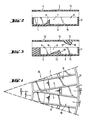
- Figur 1 einen Ausschnitt des Küvettenrotors von oben ohne Oberteil,
- Figur 2 den Schnitt II-II von Figur 1 mit Oberteil,
- Figur 3 den Schnitt III-III von Figur 1 mit Oberteil.
- Der Küvettenrotor (20) besteht aus allseitig geschlossenen Küvetten (10), die von seitlichen Wänden (7,8), einem Oberteil (14), einem Unterteil (15) und einer Stirnwand (21) begrenzt sind. Die einzelnen Küvetten (10) weisen Kamnern (1) und (2) auf, die durch einen Damm (11) voneinander getrennt sind. Der Damm (11) ist auf dem Unterteil (15) angeordnet. Der Damm (11) ist so gestaltet, daß bei dem geforderten Kammervolumen und bei stehendem Rotor ein Überlauf in die Nachbarkammer nicht stattfinden kann. Das Oberteil (14) ist mit Öffnungen (3 und 4) versehen, über die der Innenraum der Kammern (1 und 2) zugänglich ist.
- Die Zwischenräume zwischen den einzelnen Küvetten (10) sind als geschlossene Gefäße (9) zum Zentrifugieren von Proben ausgebildet. Die Gefäße (9) werden von den seitlichen Wänden (7 und 8), dem Oberteil (14), dem Unterteil (15) und der Stirnwand (21) begrenzt. Die Gefäße (9) werden durch Dämme (13), die auf dem Unterteil (15) angeordnet sind, in die Kammern (5 und 6) unterteilt. Der Innenraum der Gefäße ist über Öffnungen (22) zugänglich, die im Oberteil und zwar über der drehachsennahen Kammer (5) angeordnet sind. In die peripher angeordneten Kammern (6) ragen vom Oberteil (14) ausgehende Abweiser (12). Die Dämme (13) und die Abweiser (12) grenzen seitlich an die Wände (7 und 8) und weisen ansteigende und abfallende ebene oder gekrümmte Flächen (16, 17, 18 und 19) auf, die sich in radialer Richtung des Rotors (20) erstrecken. Die ansteigenden Flächen (16 und 17) sind weniger steil als die abfallenden Flächen (18 und 19).
- Beim Zentrifugieren bewegen sich die in der Probe vorhandenen festen Bestandteile radial in Richtung Stirnwand (21) des Gefäßes (9). Am Ende des Zentrifugiervorganges und vor dem Abbremsen der Rotationsbewegung des Küvettenrotors befinden sich alle festen Bestandteile der Probe in der peripheren Kammer (6) und zwar zwischen Stirnwand (21) und dem am Oberteil (14) angebrachten Abweiser (12), d.h. die Trennfläche zwischen festen Bestandteilen und der Flüssigkeit befindet sich senkrecht hinter dem Abweiser (12) in der peripheren Kammer (6). Beim Abbremsen der Rotationsbewegung sorgt der Abweiser (12) dafür, daß die festen Bestandteile in der peripheren Kammer (6) hinter dem Damm (13) verbleiben. Ein Teil der Flüssigkeit fließt ohne feste Bestandteile über den Damm (13) in die achsennahe Kammer (5) zurück, wo sie anschließend mit Hilfe einer Kanüle oder Pipettenspitze durch Öffnung (22) im Oberteil (14) entnommen und gegebenenfalls in die Küvette (10) transferiert werden kann.
Claims (2)
Applications Claiming Priority (2)
| Application Number | Priority Date | Filing Date | Title |
|---|---|---|---|
| DE3937609 | 1989-11-11 | ||
| DE3937609A DE3937609A1 (de) | 1989-11-11 | 1989-11-11 | Kuevettenrotor |
Publications (3)
| Publication Number | Publication Date |
|---|---|
| EP0428040A2 true EP0428040A2 (de) | 1991-05-22 |
| EP0428040A3 EP0428040A3 (en) | 1992-01-02 |
| EP0428040B1 EP0428040B1 (de) | 1996-05-15 |
Family
ID=6393367
Family Applications (1)
| Application Number | Title | Priority Date | Filing Date |
|---|---|---|---|
| EP90121192A Expired - Lifetime EP0428040B1 (de) | 1989-11-11 | 1990-11-06 | Küvettenrotor |
Country Status (8)
| Country | Link |
|---|---|
| US (1) | US5186709A (de) |
| EP (1) | EP0428040B1 (de) |
| JP (1) | JP2948898B2 (de) |
| AT (1) | ATE138193T1 (de) |
| AU (1) | AU635084B2 (de) |
| CA (1) | CA2029661C (de) |
| DE (2) | DE3937609A1 (de) |
| ES (1) | ES2088941T3 (de) |
Families Citing this family (5)
| Publication number | Priority date | Publication date | Assignee | Title |
|---|---|---|---|---|
| US5360597A (en) * | 1993-03-22 | 1994-11-01 | Eastman Kodak Company | Ribbed mechanism for mixing sample by vibration |
| US5580790A (en) * | 1994-10-21 | 1996-12-03 | Chiron Corporation | Method and apparatus for processing fluids |
| US5631166A (en) * | 1995-03-21 | 1997-05-20 | Jewell; Charles R. | Specimen disk for blood analyses |
| DE19857215B4 (de) * | 1998-12-11 | 2008-04-10 | Dade Behring Marburg Gmbh | Multiküvettenrotor |
| DE102010037009A1 (de) * | 2010-08-16 | 2012-02-16 | Drg Instruments Gmbh | Verfahren zur Analyse einer Probe |
Citations (4)
| Publication number | Priority date | Publication date | Assignee | Title |
|---|---|---|---|---|
| US3873217A (en) * | 1973-07-24 | 1975-03-25 | Atomic Energy Commission | Simplified rotor for fast analyzer of rotary cuvette type |
| EP0052770A1 (de) * | 1980-11-25 | 1982-06-02 | Roche Diagnostics GmbH | Rotoreinheit mit Einsatzelementen für einen Zentrifugalanalysator |
| US4373812A (en) * | 1981-03-25 | 1983-02-15 | Instrumentation Laboratory Inc. | Cuvette assembly |
| EP0163063A2 (de) * | 1984-05-31 | 1985-12-04 | Allied Corporation | Küvettenrotor für Zentrifugal-Analysator |
Family Cites Families (3)
| Publication number | Priority date | Publication date | Assignee | Title |
|---|---|---|---|---|
| US4902479A (en) * | 1983-11-07 | 1990-02-20 | Fisher Scientific Company | Centrifugal analyzer rotor |
| US4580897A (en) * | 1984-05-31 | 1986-04-08 | Allied Corporation | Centrifugal analyzer rotors |
| US4735502A (en) | 1986-11-21 | 1988-04-05 | Medatron, Inc. | Reusable plastic cuvette array |
-
1989
- 1989-11-11 DE DE3937609A patent/DE3937609A1/de not_active Withdrawn
-
1990
- 1990-10-26 US US07/603,550 patent/US5186709A/en not_active Expired - Lifetime
- 1990-11-06 EP EP90121192A patent/EP0428040B1/de not_active Expired - Lifetime
- 1990-11-06 DE DE59010325T patent/DE59010325D1/de not_active Expired - Lifetime
- 1990-11-06 AT AT90121192T patent/ATE138193T1/de not_active IP Right Cessation
- 1990-11-06 ES ES90121192T patent/ES2088941T3/es not_active Expired - Lifetime
- 1990-11-09 CA CA002029661A patent/CA2029661C/en not_active Expired - Lifetime
- 1990-11-09 JP JP2302821A patent/JP2948898B2/ja not_active Expired - Lifetime
- 1990-11-09 AU AU65899/90A patent/AU635084B2/en not_active Expired
Patent Citations (4)
| Publication number | Priority date | Publication date | Assignee | Title |
|---|---|---|---|---|
| US3873217A (en) * | 1973-07-24 | 1975-03-25 | Atomic Energy Commission | Simplified rotor for fast analyzer of rotary cuvette type |
| EP0052770A1 (de) * | 1980-11-25 | 1982-06-02 | Roche Diagnostics GmbH | Rotoreinheit mit Einsatzelementen für einen Zentrifugalanalysator |
| US4373812A (en) * | 1981-03-25 | 1983-02-15 | Instrumentation Laboratory Inc. | Cuvette assembly |
| EP0163063A2 (de) * | 1984-05-31 | 1985-12-04 | Allied Corporation | Küvettenrotor für Zentrifugal-Analysator |
Also Published As
| Publication number | Publication date |
|---|---|
| CA2029661A1 (en) | 1991-05-12 |
| DE3937609A1 (de) | 1991-05-16 |
| ATE138193T1 (de) | 1996-06-15 |
| EP0428040A3 (en) | 1992-01-02 |
| AU6589990A (en) | 1991-05-16 |
| DE59010325D1 (de) | 1996-06-20 |
| JP2948898B2 (ja) | 1999-09-13 |
| EP0428040B1 (de) | 1996-05-15 |
| US5186709A (en) | 1993-02-16 |
| JPH03172737A (ja) | 1991-07-26 |
| CA2029661C (en) | 2001-10-09 |
| AU635084B2 (en) | 1993-03-11 |
| ES2088941T3 (es) | 1996-10-01 |
Similar Documents
| Publication | Publication Date | Title |
|---|---|---|
| EP0405162B1 (de) | Küvettenrotor | |
| EP0039825B1 (de) | Küvetten-Rotor für Analysengerät und Verfahren zum Betrieb des Küvetten-Rotors | |
| DE2103841A1 (de) | Blutuntersuchungsvorrichtung | |
| DE2257069C2 (de) | Optischer Schnellanalysator | |
| EP0073512B1 (de) | Vorrichtung und Verfahren zum Steuern und Mischen eines der Zentrifugalkraft ausgesetzten Flüssigkeitsstromes | |
| DE2458384A1 (de) | Mehrproben-rotoranordnung zur herstellung von blutfraktionen | |
| DE2022084B2 (de) | Photometrischer Flussigkeitsanalysator vom Drehküvettentyp | |
| DE2117423C3 (de) | ||
| DE112011105686B4 (de) | Zentrifugenrotor | |
| DE2336619A1 (de) | Fotometrischer analysator | |
| DE2117423B2 (de) | Probentraeger- und transportvorrichtung | |
| DE2525211A1 (de) | Vorrichtung zur unterteilung von fluessigen proben, insbesondere fuer analysezwecke | |
| EP1008844B1 (de) | Multiküvettenrotor | |
| WO2008128534A1 (de) | Küvette für die optische analyse kleiner volumina | |
| DE2432498B2 (de) | Analysenzentrifuge | |
| EP0113118B1 (de) | Küvette zur Durchführung einer photometrischen Messung | |
| EP0428040B1 (de) | Küvettenrotor | |
| EP0160906A2 (de) | Vorrichtung zur Probenüberführung und -analyse | |
| EP0317987A2 (de) | Reaktionsgefäss zur Untersuchung flüssiger Proben im Mikroliterbereich | |
| DE102014113163B3 (de) | Reaktionsgefäß, Reaktionsgefäßanordnung und Verfahren zur Analyse einer Substanz | |
| DE7913501U1 (de) | Kuevettenkranz fuer analysengeraete | |
| CH685312A5 (de) | Vorrichtung zur Blutuntersuchung. | |
| DE202014104316U1 (de) | Reaktionsgefäß und Reaktionsgefäßanordnung zur Analyse einer Substanz | |
| DE2041053C3 (de) | Vorrichtung zum wiederholten Abgeben kleiner definierter Flüssigkeitsmengen | |
| DE2918800A1 (de) | Kuevettenanordnung fuer analysengeraete |
Legal Events
| Date | Code | Title | Description |
|---|---|---|---|
| PUAI | Public reference made under article 153(3) epc to a published international application that has entered the european phase |
Free format text: ORIGINAL CODE: 0009012 |
|
| 17P | Request for examination filed |
Effective date: 19901221 |
|
| AK | Designated contracting states |
Kind code of ref document: A2 Designated state(s): AT BE CH DE ES FR GB IT LI LU NL SE |
|
| PUAL | Search report despatched |
Free format text: ORIGINAL CODE: 0009013 |
|
| AK | Designated contracting states |
Kind code of ref document: A3 Designated state(s): AT BE CH DE ES FR GB IT LI LU NL SE |
|
| 17Q | First examination report despatched |
Effective date: 19931115 |
|
| GRAA | (expected) grant |
Free format text: ORIGINAL CODE: 0009210 |
|
| AK | Designated contracting states |
Kind code of ref document: B1 Designated state(s): AT BE CH DE ES FR GB IT LI LU NL SE |
|
| REF | Corresponds to: |
Ref document number: 138193 Country of ref document: AT Date of ref document: 19960615 Kind code of ref document: T |
|
| REF | Corresponds to: |
Ref document number: 59010325 Country of ref document: DE Date of ref document: 19960620 |
|
| ITF | It: translation for a ep patent filed |
Owner name: ING. C. GREGORJ S.P.A. |
|
| ET | Fr: translation filed | ||
| GRAH | Despatch of communication of intention to grant a patent |
Free format text: ORIGINAL CODE: EPIDOS IGRA |
|
| GBT | Gb: translation of ep patent filed (gb section 77(6)(a)/1977) |
Effective date: 19960722 |
|
| REG | Reference to a national code |
Ref country code: ES Ref legal event code: FG2A Ref document number: 2088941 Country of ref document: ES Kind code of ref document: T3 |
|
| REG | Reference to a national code |
Ref country code: ES Ref legal event code: FG2A Ref document number: 2088941 Country of ref document: ES Kind code of ref document: T3 |
|
| PLBE | No opposition filed within time limit |
Free format text: ORIGINAL CODE: 0009261 |
|
| STAA | Information on the status of an ep patent application or granted ep patent |
Free format text: STATUS: NO OPPOSITION FILED WITHIN TIME LIMIT |
|
| 26N | No opposition filed | ||
| REG | Reference to a national code |
Ref country code: CH Ref legal event code: PUE Owner name: BEHRINGWERKE AKTIENGESELLSCHAFT TRANSFER- BEHRING |
|
| REG | Reference to a national code |
Ref country code: CH Ref legal event code: PFA Free format text: BEHRING DIAGNOSTICS GMBH TRANSFER- DADE BEHRING MARBURG GMBH |
|
| REG | Reference to a national code |
Ref country code: FR Ref legal event code: CD Ref country code: FR Ref legal event code: TP |
|
| NLS | Nl: assignments of ep-patents |
Owner name: BEHRING DIAGNOSTICS GMBH |
|
| NLT1 | Nl: modifications of names registered in virtue of documents presented to the patent office pursuant to art. 16 a, paragraph 1 |
Owner name: DADE BEHRING MARBURG GMBH |
|
| REG | Reference to a national code |
Ref country code: ES Ref legal event code: PC2A |
|
| REG | Reference to a national code |
Ref country code: GB Ref legal event code: IF02 |
|
| REG | Reference to a national code |
Ref country code: GB Ref legal event code: 732E |
|
| REG | Reference to a national code |
Ref country code: CH Ref legal event code: PFA Owner name: SIEMENS HEALTHCARE DIAGNOSTICS PRODUCTS GMBH Free format text: DADE BEHRING MARBURG GMBH#POSTFACH 11 49#35001 MARBURG (DE) -TRANSFER TO- SIEMENS HEALTHCARE DIAGNOSTICS PRODUCTS GMBH#EMIL-VON-BEHRING-STRASSE 76#35041 MARBURG (DE) Ref country code: CH Ref legal event code: NV Representative=s name: SIEMENS SCHWEIZ AG |
|
| NLT1 | Nl: modifications of names registered in virtue of documents presented to the patent office pursuant to art. 16 a, paragraph 1 |
Owner name: SIEMENS HEALTHCARE DIAGNOSTICS PRODUCTS GMBH |
|
| REG | Reference to a national code |
Ref country code: FR Ref legal event code: CD |
|
| PGFP | Annual fee paid to national office [announced via postgrant information from national office to epo] |
Ref country code: SE Payment date: 20091110 Year of fee payment: 20 Ref country code: LU Payment date: 20091113 Year of fee payment: 20 Ref country code: AT Payment date: 20091019 Year of fee payment: 20 Ref country code: ES Payment date: 20091217 Year of fee payment: 20 |
|
| PGFP | Annual fee paid to national office [announced via postgrant information from national office to epo] |
Ref country code: NL Payment date: 20091118 Year of fee payment: 20 |
|
| PGFP | Annual fee paid to national office [announced via postgrant information from national office to epo] |
Ref country code: FR Payment date: 20091203 Year of fee payment: 20 Ref country code: IT Payment date: 20091125 Year of fee payment: 20 Ref country code: GB Payment date: 20091112 Year of fee payment: 20 Ref country code: CH Payment date: 20100209 Year of fee payment: 20 |
|
| PGFP | Annual fee paid to national office [announced via postgrant information from national office to epo] |
Ref country code: DE Payment date: 20100118 Year of fee payment: 20 Ref country code: BE Payment date: 20091116 Year of fee payment: 20 |
|
| REG | Reference to a national code |
Ref country code: CH Ref legal event code: PL |
|
| REG | Reference to a national code |
Ref country code: NL Ref legal event code: V4 Effective date: 20101106 |
|
| BE20 | Be: patent expired |
Owner name: *DADE BEHRING MARBURG G.M.B.H. Effective date: 20101106 |
|
| REG | Reference to a national code |
Ref country code: GB Ref legal event code: PE20 Expiry date: 20101105 |
|
| PG25 | Lapsed in a contracting state [announced via postgrant information from national office to epo] |
Ref country code: NL Free format text: LAPSE BECAUSE OF EXPIRATION OF PROTECTION Effective date: 20101106 |
|
| EUG | Se: european patent has lapsed | ||
| PG25 | Lapsed in a contracting state [announced via postgrant information from national office to epo] |
Ref country code: GB Free format text: LAPSE BECAUSE OF EXPIRATION OF PROTECTION Effective date: 20101105 |
|
| PG25 | Lapsed in a contracting state [announced via postgrant information from national office to epo] |
Ref country code: DE Free format text: LAPSE BECAUSE OF EXPIRATION OF PROTECTION Effective date: 20101106 |
|
| REG | Reference to a national code |
Ref country code: ES Ref legal event code: FD2A Effective date: 20140826 |
|
| PG25 | Lapsed in a contracting state [announced via postgrant information from national office to epo] |
Ref country code: ES Free format text: LAPSE BECAUSE OF EXPIRATION OF PROTECTION Effective date: 20101107 |