EP0427621A1 - Anlage zum Herstellen von anschliessend zur Bildung einer Baueinheit seitlich aneinanderzufügender Raumzellen - Google Patents
Anlage zum Herstellen von anschliessend zur Bildung einer Baueinheit seitlich aneinanderzufügender Raumzellen Download PDFInfo
- Publication number
- EP0427621A1 EP0427621A1 EP90403151A EP90403151A EP0427621A1 EP 0427621 A1 EP0427621 A1 EP 0427621A1 EP 90403151 A EP90403151 A EP 90403151A EP 90403151 A EP90403151 A EP 90403151A EP 0427621 A1 EP0427621 A1 EP 0427621A1
- Authority
- EP
- European Patent Office
- Prior art keywords
- elements
- subdivision
- cells
- slabs
- installation according
- Prior art date
- Legal status (The legal status is an assumption and is not a legal conclusion. Google has not performed a legal analysis and makes no representation as to the accuracy of the status listed.)
- Granted
Links
Images


Classifications
-
- B—PERFORMING OPERATIONS; TRANSPORTING
- B28—WORKING CEMENT, CLAY, OR STONE
- B28B—SHAPING CLAY OR OTHER CERAMIC COMPOSITIONS; SHAPING SLAG; SHAPING MIXTURES CONTAINING CEMENTITIOUS MATERIAL, e.g. PLASTER
- B28B7/00—Moulds; Cores; Mandrels
- B28B7/02—Moulds with adjustable parts specially for modifying at will the dimensions or form of the moulded article
-
- B—PERFORMING OPERATIONS; TRANSPORTING
- B28—WORKING CEMENT, CLAY, OR STONE
- B28B—SHAPING CLAY OR OTHER CERAMIC COMPOSITIONS; SHAPING SLAG; SHAPING MIXTURES CONTAINING CEMENTITIOUS MATERIAL, e.g. PLASTER
- B28B7/00—Moulds; Cores; Mandrels
- B28B7/22—Moulds for making units for prefabricated buildings, i.e. units each comprising an important section of at least two limiting planes of a room or space, e.g. cells; Moulds for making prefabricated stair units
-
- E—FIXED CONSTRUCTIONS
- E04—BUILDING
- E04B—GENERAL BUILDING CONSTRUCTIONS; WALLS, e.g. PARTITIONS; ROOFS; FLOORS; CEILINGS; INSULATION OR OTHER PROTECTION OF BUILDINGS
- E04B1/00—Constructions in general; Structures which are not restricted either to walls, e.g. partitions, or floors or ceilings or roofs
- E04B1/348—Structures composed of units comprising at least considerable parts of two sides of a room, e.g. box-like or cell-like units closed or in skeleton form
- E04B1/34815—Elements not integrated in a skeleton
- E04B1/34823—Elements not integrated in a skeleton the supporting structure consisting of concrete
-
- E—FIXED CONSTRUCTIONS
- E04—BUILDING
- E04G—SCAFFOLDING; FORMS; SHUTTERING; BUILDING IMPLEMENTS OR AIDS, OR THEIR USE; HANDLING BUILDING MATERIALS ON THE SITE; REPAIRING, BREAKING-UP OR OTHER WORK ON EXISTING BUILDINGS
- E04G11/00—Forms, shutterings, or falsework for making walls, floors, ceilings, or roofs
- E04G11/02—Forms, shutterings, or falsework for making walls, floors, ceilings, or roofs for rooms as a whole by which walls and floors are cast simultaneously, whole storeys, or whole buildings
Definitions
- the present invention relates to the equipment for implementing the construction process which was the subject of patent FR 2,141,580 as well as certificates of addition 2,192,220 and 2,416,310.
- the various cells which must form a single construction unit are manufactured in the factory by being placed side by side and exactly in the respective positions which will be occupied by them during their subsequent assembly at the place of construction.
- the floor slabs of the different cells of the same unit are produced by a single concrete pouring on a molding bench carrying parallel partitioning elements capable of separating the slabs belonging to each cell.
- prefabricated panels are placed vertically at the end of the different cells to form the exterior walls of the latter. These panels are then temporarily immobilized by appropriate means so as to then be secured at their base with the slabs of the different cells during the casting of these slabs.
- the equipment provided in FR 2.141.580, 2.192.220 and 2.416.310 essentially comprises a horizontal bench intended to serve as a lower molding surface for the slabs of the different cells of the same unit, as well as subdivision elements carried by this bench and which each consist of an inverted T-shaped beam.
- these subdivision beams are further used thereafter to serve as means of lifting the cells produced in order to be able to evacuate them.
- removable fixing means are provided to ensure the provisional immobilization of the prefabricated panels to be secured with cell slabs.
- the subject of the present invention is a manufacturing installation which is designed so as to eliminate this drawback in order to allow the production of cells of various dimensions.
- the design of this installation is also such that it has a certain number of improvements with respect to the equipment hitherto used for the implementation of the process in question.
- the installation according to the invention is essentially characterized in that: the elements for subdividing the slabs of the different cells are removably fixed to the manufacturing bench using fixing means making it possible to immobilize them in various positions, depending on the width provided for these cells, - At their ends, these subdivision elements carry a device for temporarily immobilizing the two prefabricated panels arranged on either side, each of these devices comprising a post whose foot can be fixed in an adjustable position on the element of corresponding subdivision, and an external stay of adjustable length.
- the present installation comprises a series of adjustable shuttering devices arranged on the production bench in order to constitute the lower shutterings of the slabs of the different cells, the edges of each of these shutters being constituted by profiles mounted to slide the one on the other so as to have an adjustable length, while the upper wall is formed by plates of varying length, placed removable on the upper edges of the sliding profiles.
- the ends of the subdivision beams of the cell slabs have a vertical cheek pierced with holes making it possible to tension, over the entire length of the edges of each cell, irons or strands d reinforcement in order to fabricate the corresponding beams at the edge of the cell slabs using the prestressed concrete technique.
- anchoring means intended to be incorporated into the ends of the cells and which are capable of receiving attachment fittings allowing the lifting thereof, one by one, after their manufacture in leaving the slab subdivision beams in place.
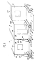
- the installation shown comprises a horizontal bench 1 intended for the production, side by side, of a series of complementary cells designated by the general reference 2 and which can then be assembled to constitute a construction unit, for example a detached house or one level of building.
- This bench 1 carries a series of horizontal elements intended to ensure the subdivision of the slabs 3 of each cell during the production of a single concrete pour above this bench.
- Each of these elements consists of a metal beam 4 in the shape of an inverted T, the horizontal wing 5 of which forms a sole intended to be placed in abutment on the top of the bench 1, while its vertical wing 6 constitutes the element properly. called subdivision of slabs.
- these various beams are arranged in parallel on the bench 1 with a spacing corresponding to the width 1 provided for the cells. So that this width can vary from one cell to another, or between two different construction units, the beams 4 are immobilized on the bench 1 by means of removable fixing means allowing different immobilization positions.
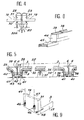
- these fixing means consist of a series of holes 7 made in metal plates 8 incorporated in the bench 1 opposite the average fixing position of one and the other ends of a beam 4
- there are provided fourteen holes 7 having the same spacing corresponding to a determined module, for example a spacing of 15 cm.
- the ends of the beams 4 are fixed by means of one or more pins 9 engaged both in one or the other of these holes and in notches 10 provided in a shoe 11 attached to the end of each of these beams.
- the fixing in place of the beams 4 is completed by immobilization of these on the bench 1 at an intermediate point of their length.
- a series of other metal plates 12, similar to the plates 8, are incorporated into this bench along the center line thereof.
- Each of these plates has a plurality of holes 13, of oval shape, intended to receive immobilization pins (not shown) engaged in holes provided in the middle of the horizontal flange of the beams 4.
- these beams are provided with a vertical cheek 14 arranged at right angles to their vertical wing 6.
- this end cheek has, on either side of the position of the vertical wing 6, a series of holes 15. These are intended to give passage to the irons or reinforcing strands 16 which must be incorporated inside the beams 17 provided on the edges of the slab 3 of each cell.
- This allows to attach, on the ends of these strands, blocking members 18 intended to bear against the corresponding cheek 14 in order to put them under tension before pouring concrete to apply the technique of prestressed concrete. It is moreover due to the forces which are thus exerted on the beams 4 during this pre-stress that there is provided an additional fixing of these on the bench 1, at an intermediate point of their length. This avoids any risk of buckling in the horizontal plane, under the effect of the pre-stress.
- each of these devices comprises a vertical post 20 and an external stay 21 of adjustable length.
- the post 20 is provided with a yoke 22 intended to be fitted on the upper edge of the vertical wing 6 of a beam 4. Its immobilization is ensured by means of a pin 23 which can be engaged in one or the other of a series of holes 24 provided in the vertical wing 6 of the corresponding beam 4. Since the post 20 is intended to be placed against the adjacent edges of two prefabricated panels, this possibility of modifying the position of its foot makes it possible to vary the length of the cells manufactured.
- the external stay 21 is of adjustable length.
- it is constituted by two profiles which can slide one over the other and be immobilized to the desired length by a pin 25.
- a rigging screw 26 allowing a finer adjustment of length.
- this forestay is fixed by means of another pin 27 on the free end of an extension 28 provided at the end of each beam 4, beyond the transverse cheek 14 thereof.
- each post 20 carries two hooks 29 formed by two metal rods 30 arranged horizontally one above the other through the corresponding holes in this post. These hooks are arranged on the inside, the opposite ends of the metal rods 30 carrying tightening nuts 30a. These metal rods are located in the gap between two neighboring prefabricated panels 19. As for the hooks 29, they are then placed as shown in FIG. 4 in order to hang inside the vertical edges of the two panels 19 corresponding against the internal face of the posts 31 provided on the edges of these panels. This therefore makes it possible to immobilize them in the vertical position provided.
- each of these devices comprises several sets of horizontal plates 35 having different lengths and the edges of which are placed in abutment on metal profiles constituting both the edges of the corresponding formwork. At an intermediate point of their length, the plates 35 also bear on a removable joist 36 resting on lower hooves 37.
- each formwork device actually comprise two complementary metal sections 38 and 39 fitted one inside the other and mounted sliding on one another. At one of its ends, each of these sections is secured to a vertical flange 44 carried by a support shoe 45 (see FIG. 6). The possibility of sliding the two sections 38 and 39 one on the other makes it possible to adjust the length of the sides of each formwork as desired.
- Insulation plates 39 for example made of polystyrene, can be placed on the plates 35 of the forms, before casting of the slabs 3.
- Other additional insulation plates 40 can be placed on either side of the sides of the different formwork, these plates resting on profiles 41.
- the horizontal base 5 of the beams 4 carries electrical heating resistances intended to accelerate the setting of the concrete.
- These resistors 42 are then advantageously arranged inside profiles 43 attached against the underside of the sole 5 of each beam.
- the present installation comprises mobile lifting means, for example an overhead crane or the like, making it possible to lift each cell 2 after completion of its manufacture in order to evacuate it out of the bench 1, leaving the beams thereon. 4 of subdivision.
- mobile lifting means for example an overhead crane or the like
- anchor rods 48 intended to be incorporated in the lateral beams 17 of the slabs 3 of the cells. The free end of each of these rods is engaged through a channel 57 formed in the lower end of the edge posts 31 of the corresponding vertical panel 19.
- the end of this anchor rod which is only flush with the external face of this panel, is intended to allow the removable fixing of an external fitting 46 for attachment, and this by means of a threaded sleeve provided with an external operating head.
- These fittings make it possible to attach slings 47 used for lifting each cell (see FIG. 9).
- the attachment fittings 46 are intended to be then removed, the anchor rods 48 remaining in place without their presence being a drawback.
- the edge posts 31 of each of these panels have, at their foot, irons 54 of connection whose ends 55 protrude horizontally outside on the inner face of the corresponding panel. These ends are intended to be thus incorporated inside the edge beams 17 of the slab 3 of the corresponding cell when the concrete of the latter is poured (see FIG. 7).
- the posts 31 have at their foot horizontal channels 56 for the passage of the strands 16 for prestressing the concrete of the slab 3, and this in addition to the channel 57 intended for the passage of the end of a rod of anchor 48.
- the position of the vertical posts 20 for immobilizing the panels 19 must be adjusted as a function of the length of the cells.
- the length of the external struts 21 may therefore have to be modified.
- these slabs consist of a single concrete pour.
- this single casting forms a succession of distinct slabs 3 each of which is specific to a cell.
- an equalization rule 52 it is possible to use an equalization rule 52 by sliding it on the upper edge of the vertical wings 6 of the two successive beams 4 of subdivision (see FIG. 5).
- cheeks 14, provided at the ends of the subdivision beams 34 have two holes 53 situated at the same level as the upper edge of the vertical wing 6 of the corresponding beam, and this on both sides. other of this wing.
- one or other of these holes can receive a metal cable which can be fixed horizontally there to serve as a guide for the equalization rule 52.
- a simple equalization rule it is possible to use a rule vibrating for the compaction of the button.
- pouring the concrete forming the slabs 3 also has the effect of securing the vertical panels 19 and the like with these slabs.
- the connection with each other is then ensured by the connecting bars 54-55 provided at the foot of the panels 19 and which are embedded in the concrete of the slabs (see FIG. 7). After setting the concrete, this therefore makes it possible to obtain cells 2 in one piece. However, as already indicated, these remain independent of each other.
- the present installation comprises two manufacturing benches 1 which are arranged side by side and equipped in the same way. With the same team of workers, it is thus possible to create two separate construction units by taking advantage of the time taken for concrete on one of these units to work on the other. This therefore results in an extremely significant time saving.
- cells 2 can be removed using a mobile lifting means, for example an overhead crane, as already described with reference to FIG. 9. These different cells can then be placed side by side side by side on another work surface where they can be fully equipped at the factory.
- a mobile lifting means for example an overhead crane
- these different cells can then be placed side by side side by side on another work surface where they can be fully equipped at the factory.
- these cells can receive all desired elements of equipment and decoration, such as floors or carpets of floors, wall coverings, elements of roof and interior ceilings and all other technical equipment, for example: electrical pipes and corresponding devices, pipes water and sanitary appliances supplied by them, heating pipes and radiators connected to them, etc.
Landscapes
- Engineering & Computer Science (AREA)
- Architecture (AREA)
- Mechanical Engineering (AREA)
- Manufacturing & Machinery (AREA)
- Chemical & Material Sciences (AREA)
- Ceramic Engineering (AREA)
- Civil Engineering (AREA)
- Structural Engineering (AREA)
- Physics & Mathematics (AREA)
- Electromagnetism (AREA)
- Forms Removed On Construction Sites Or Auxiliary Members Thereof (AREA)
- Manufacturing Of Tubular Articles Or Embedded Moulded Articles (AREA)
Applications Claiming Priority (2)
| Application Number | Priority Date | Filing Date | Title |
|---|---|---|---|
| FR8914778 | 1989-11-10 | ||
| FR8914778A FR2654379B1 (fr) | 1989-11-10 | 1989-11-10 | Installation pour la fabrication de cellules destinees a etre ensuite assemblees cote a cote pour constituer une unite de construction. |
Publications (2)
| Publication Number | Publication Date |
|---|---|
| EP0427621A1 true EP0427621A1 (de) | 1991-05-15 |
| EP0427621B1 EP0427621B1 (de) | 1993-09-15 |
Family
ID=9387286
Family Applications (1)
| Application Number | Title | Priority Date | Filing Date |
|---|---|---|---|
| EP90403151A Expired - Lifetime EP0427621B1 (de) | 1989-11-10 | 1990-11-07 | Anlage zum Herstellen von anschliessend zur Bildung einer Baueinheit seitlich aneinanderzufügender Raumzellen |
Country Status (5)
| Country | Link |
|---|---|
| US (1) | US5167842A (de) |
| EP (1) | EP0427621B1 (de) |
| DE (1) | DE69003352T2 (de) |
| ES (1) | ES2045860T3 (de) |
| FR (1) | FR2654379B1 (de) |
Families Citing this family (8)
| Publication number | Priority date | Publication date | Assignee | Title |
|---|---|---|---|---|
| US6128878A (en) * | 1998-05-08 | 2000-10-10 | Erickson; Dayle Eugene | Portable storage building with concrete floor and method of assembling and moving same |
| US6330771B1 (en) | 2000-02-04 | 2001-12-18 | Charles W. Hester, Jr. | Safer school module and assembly |
| ES2308934B1 (es) * | 2007-05-29 | 2009-09-25 | Navarra Intelligent Concrete System, S.L | Sistema automatico de construccion de edificios. |
| MX2013003931A (es) * | 2010-10-06 | 2014-10-17 | Qube Buildings Systems Inc | Sistema de construccion modular. |
| JP6480772B2 (ja) * | 2015-03-23 | 2019-03-13 | 積水化学工業株式会社 | 位置調整装置及び建物ユニットの位置調整方法 |
| SG10201603706QA (en) * | 2016-05-10 | 2017-12-28 | Dragages Singapore Pte Ltd | Method of manufacturing and assembly of a series of prefabricated prefinished volumetric construction (PPCV) modules |
| US20190217929A1 (en) * | 2018-01-17 | 2019-07-18 | Thomas J. Lefevre | Housing complex with portable housing units convertible into yachts |
| US11052569B2 (en) * | 2019-05-30 | 2021-07-06 | Jorge Cueto | Mold system for a modular telescoping barrier and method of construction |
Citations (5)
| Publication number | Priority date | Publication date | Assignee | Title |
|---|---|---|---|---|
| GB913842A (en) * | 1959-01-26 | 1962-12-28 | Albert Henderson | Apparatus and method for making concrete building components |
| FR2141580A1 (de) * | 1971-06-17 | 1973-01-26 | Vercelletto Michel | |
| FR2192220A2 (de) * | 1972-06-06 | 1974-02-08 | Vercelletto Michel | |
| FR2416310A2 (fr) * | 1978-02-03 | 1979-08-31 | Vercelletto Michel | Procede et dispositif pour la construction d'unites d'habitation prefabriquees |
| US4372906A (en) * | 1978-09-14 | 1983-02-08 | Master Modular Homes, Inc. | Method and apparatus for pre-casting steel reinforced concrete box-like modules |
Family Cites Families (7)
| Publication number | Priority date | Publication date | Assignee | Title |
|---|---|---|---|---|
| US2870517A (en) * | 1957-01-09 | 1959-01-27 | Henderson Albert | Apparatus for making concrete building segments |
| NL6817718A (de) * | 1968-12-10 | 1970-06-12 | ||
| CA999413A (en) * | 1972-05-23 | 1976-11-09 | Cornelis Van Der Lely | Methods and apparatus for the construction and/or assembly of prefabricated building sections or room units |
| US4042659A (en) * | 1974-05-06 | 1977-08-16 | Alden Joseph Botting | Method of molding modular buildings |
| SU1028507A1 (ru) * | 1976-09-16 | 1983-07-15 | Bord Mikhail N | Форма дл изготовлени объемных коробчатых изделий из бетонных смесей |
| US4673159A (en) * | 1984-10-18 | 1987-06-16 | Hancock Concrete Products Co., Inc. | Molding forms for making precast portal assembly sections for culverts |
| US4953280A (en) * | 1987-06-03 | 1990-09-04 | Gifford-Hill & Company, Inc. | Method of manufacturing prestressed concrete culverts |
-
1989
- 1989-11-10 FR FR8914778A patent/FR2654379B1/fr not_active Expired - Fee Related
-
1990
- 1990-11-07 DE DE90403151T patent/DE69003352T2/de not_active Expired - Fee Related
- 1990-11-07 EP EP90403151A patent/EP0427621B1/de not_active Expired - Lifetime
- 1990-11-07 ES ES90403151T patent/ES2045860T3/es not_active Expired - Lifetime
- 1990-11-08 US US07/610,574 patent/US5167842A/en not_active Expired - Fee Related
Patent Citations (5)
| Publication number | Priority date | Publication date | Assignee | Title |
|---|---|---|---|---|
| GB913842A (en) * | 1959-01-26 | 1962-12-28 | Albert Henderson | Apparatus and method for making concrete building components |
| FR2141580A1 (de) * | 1971-06-17 | 1973-01-26 | Vercelletto Michel | |
| FR2192220A2 (de) * | 1972-06-06 | 1974-02-08 | Vercelletto Michel | |
| FR2416310A2 (fr) * | 1978-02-03 | 1979-08-31 | Vercelletto Michel | Procede et dispositif pour la construction d'unites d'habitation prefabriquees |
| US4372906A (en) * | 1978-09-14 | 1983-02-08 | Master Modular Homes, Inc. | Method and apparatus for pre-casting steel reinforced concrete box-like modules |
Also Published As
| Publication number | Publication date |
|---|---|
| DE69003352D1 (de) | 1993-10-21 |
| US5167842A (en) | 1992-12-01 |
| EP0427621B1 (de) | 1993-09-15 |
| FR2654379B1 (fr) | 1992-03-13 |
| FR2654379A1 (fr) | 1991-05-17 |
| ES2045860T3 (es) | 1994-01-16 |
| DE69003352T2 (de) | 1994-03-17 |
Similar Documents
| Publication | Publication Date | Title |
|---|---|---|
| EP0402197A1 (de) | Vorgefertigte Schalungselemente zur Errichtung von Wänden | |
| FR2487405A1 (fr) | Module de mur pour la construction de structures en beton et procede de construction d'une structure en beton coulee sur place | |
| EP0427621B1 (de) | Anlage zum Herstellen von anschliessend zur Bildung einer Baueinheit seitlich aneinanderzufügender Raumzellen | |
| EP0285465B1 (de) | Bauelement, insbesondere Verkleidungselement mit integrierter Wärmedämmung | |
| WO1985003966A1 (fr) | Elements de structure et procede de realisation | |
| FR2578276A1 (fr) | Element de construction en beton, notamment element de plancher, et procede pour sa fabrication | |
| FR2547848A1 (fr) | Paroi prefabriquee destinee a la construction de maisons et autres batiments, et son procede de fabrication | |
| EP0147456B1 (de) | Für den bau von wänden bestimmte vorgefertigte schalungselemente, verfahren und vorrichtung dafür | |
| FR2900672A1 (fr) | Module d'habitation | |
| FR3058428B1 (fr) | Element de construction a planelle integree | |
| FR2614052A1 (fr) | Elements de construction prefabriques en beton arme, procede de fabrication de ceux-ci et murs obtenus | |
| BE502215A (de) | ||
| FR1269695A (fr) | Perfectionnements aux planchers en béton | |
| FR2604114A1 (fr) | Procede et appareillage pour la realisation d'elements prefabriques en beton arme, dans la construction | |
| FR2483306A1 (fr) | Procede et installation de fabrication de profiles en beton, et profiles ainsi obtenus | |
| FR3115308A1 (fr) | Procédé et dispositif de fixation d’un corbeau métallique de soutènement d’un mur | |
| EP0045702A1 (de) | Schalung | |
| FR2473589A1 (fr) | Procede pour la realisation d'ossature porteuse de batiment a partir d'elements metalliques prefabriques et elements pour la mise en oeuvre du procede | |
| FR2483987A1 (fr) | Cadre prefabrique et construction en comportant application | |
| FR2789710A1 (fr) | Dispositif permettant de realiser des reservations de fenetres, portes, lors de la construction d'un batiment et procede pour sa mise en oeuvre | |
| FR2469526A1 (fr) | Stabilisateur de banche | |
| FR2762340A1 (fr) | Dispositif de securite pour dalles alveolees en beton et dalles comportant ce dispositif | |
| BE565583A (de) | ||
| FR2967182A1 (fr) | Procede de mise en oeuvre de reservations dans des voiles en beton arme pour permettre la realisation de planchers suspendus | |
| FR2695151A1 (fr) | Procédé pour la réalisation d'une rive de plancher, éléments de construction pour la mise en Óoeuvre de ce procédé et rive de plancher ainsi réalisée. |
Legal Events
| Date | Code | Title | Description |
|---|---|---|---|
| PUAI | Public reference made under article 153(3) epc to a published international application that has entered the european phase |
Free format text: ORIGINAL CODE: 0009012 |
|
| AK | Designated contracting states |
Kind code of ref document: A1 Designated state(s): DE ES GB IT |
|
| 17P | Request for examination filed |
Effective date: 19911109 |
|
| 17Q | First examination report despatched |
Effective date: 19930222 |
|
| GRAA | (expected) grant |
Free format text: ORIGINAL CODE: 0009210 |
|
| AK | Designated contracting states |
Kind code of ref document: B1 Designated state(s): DE ES GB IT |
|
| PG25 | Lapsed in a contracting state [announced via postgrant information from national office to epo] |
Ref country code: GB Effective date: 19930915 |
|
| ITF | It: translation for a ep patent filed |
Owner name: CALVANI SALVI E VERONEL |
|
| REF | Corresponds to: |
Ref document number: 69003352 Country of ref document: DE Date of ref document: 19931021 |
|
| REG | Reference to a national code |
Ref country code: ES Ref legal event code: FG2A Ref document number: 2045860 Country of ref document: ES Kind code of ref document: T3 |
|
| GBV | Gb: ep patent (uk) treated as always having been void in accordance with gb section 77(7)/1977 [no translation filed] |
Effective date: 19930915 |
|
| PLBE | No opposition filed within time limit |
Free format text: ORIGINAL CODE: 0009261 |
|
| STAA | Information on the status of an ep patent application or granted ep patent |
Free format text: STATUS: NO OPPOSITION FILED WITHIN TIME LIMIT |
|
| 26N | No opposition filed | ||
| PGFP | Annual fee paid to national office [announced via postgrant information from national office to epo] |
Ref country code: ES Payment date: 19981130 Year of fee payment: 9 |
|
| PGFP | Annual fee paid to national office [announced via postgrant information from national office to epo] |
Ref country code: DE Payment date: 19990129 Year of fee payment: 9 |
|
| PG25 | Lapsed in a contracting state [announced via postgrant information from national office to epo] |
Ref country code: ES Free format text: LAPSE BECAUSE OF NON-PAYMENT OF DUE FEES Effective date: 19991108 |
|
| PG25 | Lapsed in a contracting state [announced via postgrant information from national office to epo] |
Ref country code: DE Free format text: LAPSE BECAUSE OF NON-PAYMENT OF DUE FEES Effective date: 20000901 |
|
| REG | Reference to a national code |
Ref country code: ES Ref legal event code: FD2A Effective date: 20001214 |
|
| PG25 | Lapsed in a contracting state [announced via postgrant information from national office to epo] |
Ref country code: IT Free format text: LAPSE BECAUSE OF NON-PAYMENT OF DUE FEES;WARNING: LAPSES OF ITALIAN PATENTS WITH EFFECTIVE DATE BEFORE 2007 MAY HAVE OCCURRED AT ANY TIME BEFORE 2007. THE CORRECT EFFECTIVE DATE MAY BE DIFFERENT FROM THE ONE RECORDED. Effective date: 20051107 |