EP0425934B2 - Semoir en ligne pour semence - Google Patents
Semoir en ligne pour semence Download PDFInfo
- Publication number
- EP0425934B2 EP0425934B2 EP90120082A EP90120082A EP0425934B2 EP 0425934 B2 EP0425934 B2 EP 0425934B2 EP 90120082 A EP90120082 A EP 90120082A EP 90120082 A EP90120082 A EP 90120082A EP 0425934 B2 EP0425934 B2 EP 0425934B2
- Authority
- EP
- European Patent Office
- Prior art keywords
- seed
- adjusting means
- delivery
- signal
- drill device
- Prior art date
- Legal status (The legal status is an assumption and is not a legal conclusion. Google has not performed a legal analysis and makes no representation as to the accuracy of the status listed.)
- Expired - Lifetime
Links
- 238000010899 nucleation Methods 0.000 title description 2
- 238000012384 transportation and delivery Methods 0.000 claims description 43
- 230000001419 dependent effect Effects 0.000 claims description 2
- 238000005553 drilling Methods 0.000 description 6
- 230000005540 biological transmission Effects 0.000 description 3
- 238000001514 detection method Methods 0.000 description 3
- 238000012935 Averaging Methods 0.000 description 2
- 238000011161 development Methods 0.000 description 2
- 230000018109 developmental process Effects 0.000 description 2
- 238000006073 displacement reaction Methods 0.000 description 2
- 238000005259 measurement Methods 0.000 description 2
- 235000010469 Glycine max Nutrition 0.000 description 1
- 244000068988 Glycine max Species 0.000 description 1
- 238000004364 calculation method Methods 0.000 description 1
- 238000006243 chemical reaction Methods 0.000 description 1
- 238000010276 construction Methods 0.000 description 1
- 238000012937 correction Methods 0.000 description 1
- 238000005520 cutting process Methods 0.000 description 1
- 238000005516 engineering process Methods 0.000 description 1
- 230000001771 impaired effect Effects 0.000 description 1
- 238000012423 maintenance Methods 0.000 description 1
- 230000007257 malfunction Effects 0.000 description 1
- 238000004519 manufacturing process Methods 0.000 description 1
- 238000000034 method Methods 0.000 description 1
- 238000012986 modification Methods 0.000 description 1
- 230000004048 modification Effects 0.000 description 1
- 238000012544 monitoring process Methods 0.000 description 1
- 230000002441 reversible effect Effects 0.000 description 1
- 238000007493 shaping process Methods 0.000 description 1
- 230000011664 signaling Effects 0.000 description 1
- 238000003860 storage Methods 0.000 description 1
- 230000001960 triggered effect Effects 0.000 description 1
Images

Classifications
-
- A—HUMAN NECESSITIES
- A01—AGRICULTURE; FORESTRY; ANIMAL HUSBANDRY; HUNTING; TRAPPING; FISHING
- A01C—PLANTING; SOWING; FERTILISING
- A01C7/00—Sowing
- A01C7/08—Broadcast seeders; Seeders depositing seeds in rows
- A01C7/10—Devices for adjusting the seed-box ; Regulation of machines for depositing quantities at intervals
- A01C7/102—Regulating or controlling the seed rate
-
- Y—GENERAL TAGGING OF NEW TECHNOLOGICAL DEVELOPMENTS; GENERAL TAGGING OF CROSS-SECTIONAL TECHNOLOGIES SPANNING OVER SEVERAL SECTIONS OF THE IPC; TECHNICAL SUBJECTS COVERED BY FORMER USPC CROSS-REFERENCE ART COLLECTIONS [XRACs] AND DIGESTS
- Y10—TECHNICAL SUBJECTS COVERED BY FORMER USPC
- Y10S—TECHNICAL SUBJECTS COVERED BY FORMER USPC CROSS-REFERENCE ART COLLECTIONS [XRACs] AND DIGESTS
- Y10S111/00—Planting
- Y10S111/903—Monitor
- Y10S111/904—Population control function
Definitions
- the invention relates to a seed drill, which is, for example, part of a seed drill, with a plurality of seed dosers arranged next to one another, each having a rotatable metering element arranged in an associated metering housing, and also with drive means for rotating the metering elements as a function of the driving speed of the seed drill, so that the Seed delivery depends on the driving speed, and with adjusting means for adjusting the position of the metering elements transversely to the direction of travel, as a result of which the seed delivery can be adjusted.
- Seed drills usually contain several seed metering devices, which are arranged transversely to the direction of travel and are spaced apart from one another, with corrugated feed wheels, which are driven by a wheel of the seed drill touching the ground, so that a seed quantity is discharged per unit of time, which is proportional to the drive speed of the seed drill. This always results in the same amount of seed being dispensed per unit area driven, regardless of the driving speed.
- the gear ratio between the wheel of the seeding device and the ary drive shaft driving the feed wheels is changed, or it is the feed wheels shifted within the dosing housing surrounding them. The latter is done manually by sliding the drive shaft to the side, which changes the effective dosing range of the feed wheels.
- Rough adjustments for example to adjust the dosage to different types of seeds, are usually carried out by changing the feed gates of the metering devices and / or by changing the transmission ratio.
- EP-A-0 254 218 describes an agricultural distributor machine with a storage container, from which the seed to be spread is fed to a plurality of metering elements, which are arranged on a metering shaft and are designed as cam wheels, and are arranged in a rotationally fixed manner.
- the metering shaft is driven by a power source via a continuously variable control gear and a chain drive. By influencing the speed of the metering shaft, the amount of seed applied can be adjusted.
- the measured value of the seed quantity detected by the sensor and the signal from a distance measuring device are fed to a microprocessor, which uses this to calculate an actual value and compares it with an inputable target value.
- the microprocessor sends control signals to a servomotor, which correspondingly adjusts the control lever of a control gear and adjusts the speed of the metering shaft and thus the amount of seed applied.
- the metering elements are driven by a power source, not specified.
- a relatively complex control linkage and gearbox is required, which must cover a very large control range.
- a fine metering of the seed quantity applied is hardly possible.
- the object to be achieved with the invention is seen in providing an improved metering system for a seed drill of the type mentioned at the outset, with which the problems mentioned can be overcome. It should be possible to set the adjusting means in a convenient manner, adapted to the changing requirements of the company.
- This control which is preferably carried out largely automatically and electrically or electronically, considerably improves the metering option.
- the setting of the seed delivery can easily be changed from any location, for example from the vehicle cabin of a tractor, even while driving and adjusted by an operator and adapted to different conditions.
- the control allows fine metering even when the other setting options are relatively rough, such as setting the drive means for rotating the metering elements by exchanging gear wheels and / or changing the feed gate setting.
- the drilling device according to the invention is relatively simple in construction and inexpensive to manufacture. It can be easily expanded for an application to larger and / or divided into several sectors.
- the same electronics can also be used in the drilling device for individual drilling machines as well as for multiplex drilling machine arrangements.
- the seed metering device preferably contains a grooved feed drum which can be moved laterally within a housing and which can be rotated and moved laterally by a drive shaft.
- the lateral shift is carried out by the automatic control according to the invention.
- several seed dosers are provided with a seed sensor for detecting the seed release, the measurement signals of which are used to generate a signal corresponding to the seed release.
- a seed sensor for detecting the seed release, the measurement signals of which are used to generate a signal corresponding to the seed release.
- the required number can be chosen based on the requirements from the company.
- the setting means are controlled as a function of the seed delivery.
- control means are provided, by means of which the seed delivery signals of the seed sensor are initially averaged. The mean value is then compared with a target value for the seed delivery which can be predetermined by an input device. An error signal is formed from the difference between the setpoint and actual value, which is used for the automatic tracking of the setting means and thus for the granting of a constant seed delivery.
- a drive can be provided, by means of which the corrugated feed wheels can be displaced within their metering housing in the direction of the axis of rotation, as a result of which the seed delivery is changed.
- an alarm device preferably emits a signal that is perceptible to the operator, as a result of which the operator is made aware of the fault.
- means for detecting the position of the setting means can also be expediently provided, the signal of which is used in order to emit signals which are perceptible to the operator when a predetermined limit position of the setting means is reached.
- the invention can be used particularly advantageously if at least two sets of seed dispensers are provided, each of which contains separate drive means for rotation and adjusting means for adjusting the seed delivery. At least one seed sensor can be assigned to each set here. For each set, a separate signal for seed delivery is generated, which is used for the automatic actuation of the associated setting means.
- a switch or multiplex circuit enables a single control device to be sufficient to control the setting means sequentially. In spite of separately operating seed metering devices, it is therefore possible to use only one control device operated in multiplex mode for each separate closed control loop. As a result, costs can be saved and the complexity of the system reduced without the seed control, which can also be carried out while driving, being impaired.
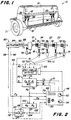
- FIG. 1 and 2 show a grain seed drill 10 which contains at least one set of metering devices 12 which is arranged between a seed hopper 14 and cutting tools 18.
- the metering devices 12 are connected to a drive shaft 22 and are driven by a conventional drive arrangement 26 by a wheel 28 touching the ground in order to discharge a seed quantity which is proportional to the driving speed of the seed drill 10.
- the metering devices 12 are preferably those as described in US Pat 4,408,704. S.ie contain laterally displaceable, corrugated feed wheels 32 which are slidably received by dosing housings 34. By moving the grooved feed wheel 32 laterally within the metering housing 34, the effective metering range of the feed wheel 32 is changed so that the seed delivery of each metering device 12 can be varied.
- the feed wheels 32 of the metering devices 12 are fastened on the drive shaft 22, which can be moved laterally, so that all metering devices on the shaft 22 can be adjusted together. For example, if the operator desires a slight increase (or decrease) in seed delivery by the metering devices 12, they can move the shaft 22 to the right (or left), as shown in FIG.
- Each of the metering devices 12 is connected to a seed tube 36, which in turn is connected to one of the furrow pulling tools 18.
- n metering devices, M 1 - M n are connected to the drive shaft 22.
- Seed detection devices 42 are connected to nx (nx is at least 1, but preferably less than n) of the seed tubes 36.
- the seed detection devices 42 can be those that are offered by Pioneer Technology of Sunnyvale, California, USA.
- the (nx) outputs are connected to input terminals of a control circuit 44, which in turn is connected to an input / output / alarm signaling device (I / O) 46.
- the I / O device 46 contains a reading device 48 which optionally outputs the average seed delivery of the monitored metering devices 12 or various other information.
- Such information is, for example, input parameters (target value of the seed output R d , row spacing W, number N of rows and desired units of measured variables, such as the actual values of the number of seeds or the seed volume or weight C u ), which are entered into the control circuit 44 are used to calculate information for seed delivery.
- a keyboard 50 or other conventional input device is used to input variables selectable by the multi-position control switch 52.
- Output variables that are to be displayed on the read-out device 48 can be selected by a second operating switch 54.
- Such output sizes are, for example the calculated seed delivery, the difference between the current and desired seed delivery and a position indication of the drive shaft 22.
- the control circuit 44 comprises a circuit 60 which has a plurality of inputs 62 connected to the individual seed detection devices 42 and which serves to average the input values.
- the circuit 60 sums up the measurement signals of the number of seeds or the seed masses N y from the (nx) sensors 42 over a period of time dt and supplies an average signal A 1 for the seed delivery to an output contact 64.
- the circuit 60 may include a comparison circuit 65 for comparing the average signal A 1 with the individual signals of each of the sensors 42.
- d p e.g. D y > d p
- the output contact 64 of the averaging circuit 60 is connected to an input contact of a circuit 70 for determining the seed release.
- the output value of a shaft speed sensor 72 is also connected to the circuit 70. It supplies a speed signal S 1 , which is characteristic of the speed of advance of the seed drill 10.
- the circuit 70 is informed via line 71 of variable input variables for the row spacing W, the number N of rows and required conversion variables C u which can be entered via the keyboard 50.
- An output contact 78 is connected to an input 79 of the I / O device 46 to allow a display on the display 48 via the seed delivery actual R a.
- the value of the seed tax can be spent in seeds, volume, or weight per acre or hectare, depending on which unit has been selected by the operator and which unit corresponds to local habits.
- a drive 80 is functionally connected to the drive shaft 22 for the metering devices 12 such that the drive shaft 22 is laterally displaceable , whereby the effective metering ranges of the corrugated feed wheels 32, which are connected to the shaft 22, can be changed.
- the drive 80 is preferably an electric linear drive with a rotatable threaded part 82 which can be moved inwards or outwards by a reversible motor 84.
- a positive or negative input voltage which is formed by the circuit 44, is applied via line 86 to an input contact of the drive.
- the threaded part 82 can be driven either continuously or in certain steps with a fixed amount.
- a hydraulic circuit can be used that contains a hydraulic drive for adjusting the drive shaft 22.
- the end of the threaded part 82 is connected to the drive shaft 22 via a bearing shell 88, which allows a relative rotation between the drive shaft 22 and the threaded part 82, but firmly connects the drive shaft 22 to the threaded part 82 for axial movements.
- a feedback signal F p is provided to a feedback line 90 by a potentiometer or other device that detects the position of the shaft 22, which may be included in the drive.
- Line 90 is connected to I / O device 46.
- an operator can display the output signal for the drive position on the display 48 and read whether the grooved feed wheels 32 are operating within a range that still allows lateral displacement.
- a detector circuit is provided in the I / O device 46, which supplies a warning signal when the signal F p reaches a first or second value that corresponds to an end position or a maximum setting position of the drive shaft 22. The warning signal alerts the operator that further adjustment of the drive shaft 22 in the given direction is no longer possible.
- the drive 80 is part of a closed control loop that includes the control circuit 44. This automatically delivers a correction signal via line 86 to the Shift drive shaft 22 laterally and reduce a difference between the actual value of the seed delivery R a and its target value R d .
- an operating element (not shown) can be provided on the front plate of the I / O device or at another conveniently accessible location in the tractor cab, by means of which the operator can manually set a target value for the shaft displacement depending on the display of the reading device 48 Tractor cab can choose from.
- the operator can set the difference signal D r to be shown on the display 48 by adjusting the operating switch 54 and then adjust the drive 80 by one or more steps in the required direction to fine-tune the seed output, so that the error signal is reduced.
- the motor is driven in the desired direction for a short time.
- the error signal D r is fed via line 104 to the input of the control circuit 110 for the drive 80.
- the control circuit 110 contains an output amplifier 112, the output of which assumes the reference voltage when the error signal is within certain limits. However, if the error signal lies outside these limits, the output amplifier 112 supplies an output signal whose polarity with respect to the reference voltage is determined by the error signal D r . If the error signal is negative because the actual seed delivery value is greater than a specific target delivery, a negative signal is applied to the drive 80 in order to retract the threaded part 82 and thus to move the shaft 22 to the left according to FIG. 2. As a result, the effective metering range of the corrugated feed wheels 32 and thus also the seed delivery are reduced.
- the seed delivery setpoint is less than the actual value, a positive signal is applied to the drive 80, as a result of which the threaded part 82 is extended and the effective metering range of the grooved feed wheels 32 is increased.
- the number of pulses (or the length of the signal) that are output from the output amplifier 112 to the line 86 is determined by the pulse shaper circuit 114 which controls the amplifier output so that the drive signal is dependent on the magnitude and Polarity of the error signal is formed at the input of the drive control circuit 110.
- the feedback signal F p which corresponds to the actual position of the drive 80, can be applied to a control input 116 of the pulse shaping circuit 114, so that the amplifier 112 is driven with an input signal of the required polarity until the feedback signal F p has a predetermined value Amount changes, this amount depending on the size of the error signal D r .
- the error signal D r can, for example, by a timer circuit, such as. B. an RC network, which specifies a time interval that depends on the size of the error signal, are controlled.
- An unusually large error signal at the output of the circuit 100 is detected by the I / O device 46, which emits an acoustic and / or visible signal to alert the operator of a possible malfunction in the dosing system.
- control circuit 44 Conventional analog or digital techniques can be used in the control circuit 44. If desired, the functions of the control circuit 44 and the I / O device can be based on microprocessors.
- FIG. 3 shows an alternative embodiment of the invention.
- the seed deliveries of several partial areas or individual seed drills 10a - 10b are monitored and controlled with a single control circuit 44 and an I / O device 46a.
- the seed detectors 42 of each seed drill or each seed area are optionally in sequence via a switchover or
- Multiplex circuit 120 connected to the input of the averaging circuit 60.
- a control line connects the I / O device 46a to the multiplex circuit 120 and a selector switch 124 allows the operator to control the multiplex circuit 120 to determine which drill or drill area is monitored.
- the circuit 120 also connects the output 86 of the circuit 110 and the return line 90 to the drive 80 of the monitored seed drill.
- the actuation of the circuit 44 by the control device 46a for controlling the seed delivery of a selected seed drill is essentially identical to that described above with reference to FIG. 2.
- the I / O device may include a circuit that continuously switches the multiplexing circuit 120 to the seed drills so that the seed deliveries are automatically monitored and continually adjusted to keep the seed deliveries of the seed drills 10a-10c within desired limits hold.
- the circuit according to FIG. 3 can also be used in a feedback-free control circuit by a control device which can be set by the operator from a remote location is provided for the desired drive 10a-10c while the corresponding seed drill to be monitored is selected by
Landscapes
- Life Sciences & Earth Sciences (AREA)
- Soil Sciences (AREA)
- Environmental Sciences (AREA)
- Sowing (AREA)
Claims (8)
- Semoir en ligne pour semences, avec plusieurs doseurs de semences juxtaposés (M), qui présentent chacun un organe doseur rotatif (32) disposé dans un boîtier de doseur associé (34), avec des moyens d'entraînement (22,26) pour faire tourner les organes doseurs (32) en fonction de la vitesse de déplacement de la semeuse (10) équipée du semoir en ligne, de sorte que la délivrance de semences dépend de la vitesse de déplacement, et avec un moyen de réglage (80) pour modifier la position des organes doseurs (32) transversalement à la direction de déplacement, permettant ainsi de régler la délivrance de semences, caractérisé en cequ'à plusieurs des doseurs de semences (My) est associé respectivement un capteur de semences (42) servant à détecter la délivrance de semences et dont les signaux de mesure (Ny) sont utilisés pour produire un signal (Ra) correspondant à la délivrance de semences,qu'il est prévu un formateur de valeur moyenne (60), qui forme un signal (A1) de délivrance moyenne de semences à partir des signaux de mesure (Ny) des capteurs de semences (42),que le moyen de réglage (80) est commandé en fonction de la délivrance de semences, etqu'il est prévu une unité de commande (44,46), qui peut être actionnée à partir d'un emplacement éloigné et au moyen de laquelle le moyen de réglage (80) servant à décaler la position des organes doseurs (32) peut être également déplacé pendant le déplacement du semoir.
- Semoir en ligne selon la revendication 1, caractérisé en ce qu'un doseur de semences (M) comprend un tambour d'alimentation cannelé (32) latéralement déplaçable à l'intérieur d'un boîtier (34), le tambour (32) pouvant être mis en rotation et déplacé latéralement par un arbre d'entraînement (22).
- Semoir en ligne selon la revendication 1 ou 2, caractérisé en ce qu'l est prévu un moyen de commande (100), qui compare le signal de délivrance de semences (Ra) du ou des capteurs de semences (42) à au moins une consigne de délivrance de semences (Rd) prédéfinissable par une unité d'introduction de données (46), et qui forme un signal d'erreur (Dr) servant à ajuster automatiquement le moyen de réglage (80).
- Semoir en ligne selon l'une quelconque des revendications 1 à 3, caractérisé en ce que le moyen de réglage (80) permet de déplacer latéralement au moins n doseurs de semences (M), n étant un nombre entier supérieur à 1, et en ce qu'un capteur de semences respectif (42) est associé à n-x des n doseurs de semences (M), n-x étant un nombre entier supérieur ou égal à 1 mais inférieur à n.
- Semoir en ligne selon l'une quelconque des revendications 3 à 4, caractérisé en ce qu'il est prévu une unité de signalisation (46), qui délivre des signaux pouvant être perçus par l'opérateur lorsque le signal d'erreur (Dr) dépasse une valeur limite prédéfinissable.
- Semoir en ligne selon l'une quelconque des revendications 1 à 5, caractérisé en ce qu'il est prévu un moyen pour détecter la position du moyen de réglage (80), et en ce que des signaux pouvant être perçus par l'opérateur sont délivrés à l'atteinte d'une position limite prédéfinissable du moyen de réglage (80).
- Semoir en ligne selon l'une quelconque des revendications 1 à 6, caractérisé en ce qu'il est prévu au moins deux groupes de doseurs de semences (M), qui comprennent chacun des moyens d'entraînement séparés (22,26) pour leur mise en rotation et un moyen de réglage séparé (80a, 80b, 80c) pour modifier la délivrance de semences, et en ce qu'au moins un capteur de semences (42) est associé à chaque groupe, et en ce qu'un signal séparé de délivrance de semences est formé pour chaque groupe, signal qui est utilisé pour l'actionnement automatique du moyen de réglage associé (80a, 80b, 80c).
- Semoir en ligne selon la revendication 7, caractérisé en ce qu'il est prévu un moyen de commande électronique (120), qui évalue successivement les signaux de mesure (Ny) des groupes et les utilise pour commander le moyen de réglage associé (80a, 80b, 80c).
Applications Claiming Priority (2)
| Application Number | Priority Date | Filing Date | Title |
|---|---|---|---|
| US07/429,664 US5025951A (en) | 1989-10-31 | 1989-10-31 | Electronic seed rate system for a grain drill |
| US429664 | 1989-10-31 |
Publications (3)
| Publication Number | Publication Date |
|---|---|
| EP0425934A1 EP0425934A1 (fr) | 1991-05-08 |
| EP0425934B1 EP0425934B1 (fr) | 1994-04-20 |
| EP0425934B2 true EP0425934B2 (fr) | 1997-01-08 |
Family
ID=23704218
Family Applications (1)
| Application Number | Title | Priority Date | Filing Date |
|---|---|---|---|
| EP90120082A Expired - Lifetime EP0425934B2 (fr) | 1989-10-31 | 1990-10-19 | Semoir en ligne pour semence |
Country Status (6)
| Country | Link |
|---|---|
| US (1) | US5025951A (fr) |
| EP (1) | EP0425934B2 (fr) |
| AU (1) | AU639477B2 (fr) |
| CA (1) | CA2027821C (fr) |
| DE (1) | DE59005441D1 (fr) |
| ES (1) | ES2051433T5 (fr) |
Families Citing this family (46)
| Publication number | Priority date | Publication date | Assignee | Title |
|---|---|---|---|---|
| US5189965A (en) * | 1990-05-02 | 1993-03-02 | Holdrege Seed And Farm Supply Company | Granular materials applicator |
| US5170730A (en) * | 1991-04-22 | 1992-12-15 | Kansas State University Research Foundation | Seed planter for continuously planting plots using different seed sources |
| US5666893A (en) * | 1992-08-18 | 1997-09-16 | Bourgeois; Raymond A. | Crop sprayer guidance system |
| DE9216015U1 (de) * | 1992-11-25 | 1993-02-18 | Rabewerk Bernburg GmbH + Co, O-4350 Bernburg | Drillmaschine |
| FR2716068B1 (fr) * | 1994-02-14 | 1996-04-26 | Patrick Charles George Auberge | Perfectionnements au fonctionnement et au réglage des machines distributrices de graines, à distribution volumétrique, notamment aux semoirs en ligne. |
| US5632212A (en) * | 1995-01-20 | 1997-05-27 | Kinze Manufacturing, Inc. | Dual-speed clutch for agricultural planter |
| US5598794A (en) * | 1995-02-13 | 1997-02-04 | Fluid Power Industries, Inc. | High accuracy automatically controlled variable linear seed spacing planting apparatus |
| FR2730897B1 (fr) * | 1995-02-25 | 1998-04-17 | Rauch Landmaschfab Gmbh | Semoir a debit pre-reglable telecommande |
| US6070538A (en) * | 1996-11-22 | 2000-06-06 | Case Corporation | Modular agricultural implement control system |
| US5924371A (en) * | 1997-09-23 | 1999-07-20 | Case Corporation | Global controller and distributed local controller(s) for an agricultural implement |
| US6024035A (en) * | 1997-09-23 | 2000-02-15 | Case Corporation | Seed planting rate maintenance control with rate display |
| US6091997A (en) * | 1997-09-23 | 2000-07-18 | Case Corporation | Enhanced statistical/status display |
| US5956255A (en) * | 1997-09-23 | 1999-09-21 | Case Corporation | Seed planter performance monitor |
| US6009354A (en) * | 1997-09-23 | 1999-12-28 | Case Corporation | Enhanced implement control |
| US6003455A (en) * | 1998-03-05 | 1999-12-21 | Case Corporation | Regulator control |
| CA2252321A1 (fr) * | 1998-10-30 | 2000-04-30 | Blake Robert Neudorf | Systeme d'amorcage pour distributeurs de produits agricoles |
| EP0997064B8 (fr) | 1998-10-30 | 2004-07-14 | CNH Canada Ltd. | Dispositif de démarrage pour machines de distribution de produits agricoles |
| US6145455A (en) * | 1999-03-17 | 2000-11-14 | Case Corporation | Agricultural material metering system |
| US6109192A (en) | 1999-09-20 | 2000-08-29 | Deere & Company | Power rate adjustment mechanism for a seeding implement |
| US6357369B1 (en) | 2000-08-15 | 2002-03-19 | James Sidles | Rotating seed drill |
| US7273016B2 (en) * | 2004-05-20 | 2007-09-25 | Deere & Company | Variable speed drive for agricultural seeding machines |
| AR045454A1 (es) * | 2004-08-13 | 2005-10-26 | Abelardo Atilio Cuffia | Instalacion electromecanica de control y mando para la dosificacion de semillas y fertilizantes con capacidad de variacion durante la siembra |
| ES2627181T5 (es) * | 2007-01-08 | 2021-01-11 | Climate Corp | Sistema y método de monitorización de plantadora |
| US20110015831A1 (en) * | 2009-07-17 | 2011-01-20 | Loup Electronics, Inc. | Application rate system for a farm implement |
| US8601963B2 (en) | 2011-01-06 | 2013-12-10 | Cnh Canada, Ltd. | Seed metering assembly having modular and independently controlled metering units |
| US8714097B2 (en) | 2011-01-06 | 2014-05-06 | Cnh Industrial Canada, Ltd. | Seed metering cassette for seeding implement |
| US8701576B2 (en) | 2011-01-06 | 2014-04-22 | Cnh Canada, Ltd. | Seed hopper for seed metering system having modular seed metering units |
| US8671857B2 (en) | 2011-03-10 | 2014-03-18 | Cnh Canada, Ltd. | Variable geometry meter roller |
| LT3202245T (lt) | 2012-07-25 | 2020-10-12 | Precision Planting Llc | Integruotasis padargo prispaudimo jėgos valdiklis |
| EP3010326B1 (fr) * | 2013-06-21 | 2018-10-17 | Precision Planting LLC | Système de sélection de variété d'entrée de culture |
| US9320192B2 (en) | 2013-11-12 | 2016-04-26 | Dickey-John Corporation | Synchronization of a twin row planting system |
| CA2904286C (fr) | 2014-11-04 | 2021-10-19 | Cnh Industrial Canada, Ltd. | Rouleaux doseurs anneles et mecanisme de degagement lateral |
| CA2904759C (fr) | 2014-11-04 | 2021-01-12 | Cnh Industrial Canada, Ltd. | Systeme et methode de dosage de produits agricoles |
| CA3093261C (fr) | 2014-11-04 | 2022-07-26 | Cnh Industrial Canada, Ltd. | Rouleaux doseurs anneles et mecanisme de degagement lateral |
| US9526201B2 (en) | 2015-01-05 | 2016-12-27 | Cnh Industrial America Llc | Twin-row planter with tandem driven seed meters |
| US10709058B2 (en) | 2015-08-31 | 2020-07-14 | Cnh Industrial Canada, Ltd. | Flow control system for an agricultural metering system |
| US9854732B2 (en) | 2015-08-31 | 2018-01-02 | Cnh Industrial Canada, Ltd. | Metering system for an agricultural vehicle |
| US9661805B1 (en) | 2015-12-29 | 2017-05-30 | Ball Horticultural Company | Seed sowing system and method of use |
| US10379547B2 (en) | 2017-07-26 | 2019-08-13 | Cnh Industrial Canada, Ltd. | System and method for calibrating a material metering system |
| US10481617B2 (en) * | 2017-08-10 | 2019-11-19 | Cnh Industrial Canada, Ltd. | Metering system for an agricultural system |
| US11032964B2 (en) | 2018-06-27 | 2021-06-15 | Cnh Industrial Canada, Ltd. | Flow splitting control valve for secondary header |
| CN109387388B (zh) * | 2018-12-28 | 2024-01-12 | 中国农业大学 | 一种通用型排种性能检测仪 |
| US11765991B2 (en) | 2019-11-14 | 2023-09-26 | Cnh Industrial Canada, Ltd. | Particulate material metering system for an agricultural implement |
| CA3097708A1 (en) | 2019-11-14 | 2021-05-14 | Cnh Industrial Canada, Ltd. | Particulate material metering system for an agricultural implement |
| US11980120B2 (en) | 2021-09-03 | 2024-05-14 | Cnh Industrial Canada, Ltd. | Agricultural product storage compartment assembly having a weight monitoring system |
| US12349614B2 (en) | 2021-11-10 | 2025-07-08 | Deere & Company | Air seeding turn compensation using yaw rate from sensor on towing vehicle |
Family Cites Families (17)
| Publication number | Priority date | Publication date | Assignee | Title |
|---|---|---|---|---|
| US3355102A (en) * | 1965-09-13 | 1967-11-28 | Calark Inc | Seed planter feeding indicator and counting mechanism and circuit control device |
| US3537091A (en) * | 1967-10-05 | 1970-10-27 | Case Co J I | Seed monitoring system |
| US3511411A (en) * | 1967-12-11 | 1970-05-12 | Ambac Ind | Apparatus for controlling planting and material spraying and spreading device |
| GB1274673A (en) * | 1968-10-03 | 1972-05-17 | Massey Ferguson Perkins Ltd | Improvements in metering devices |
| FR2326137A1 (fr) * | 1975-10-03 | 1977-04-29 | Dickey John Corp | Appareil de controle de semis |
| CA1075087A (fr) * | 1976-04-16 | 1980-04-08 | Harold V. Hansen | Commande de semoir a debit variable |
| FR2423963A1 (fr) * | 1978-04-24 | 1979-11-23 | Mezogazdasagi Gepkiserleti Int | Dispositif de controle de distribution de semences, notamment pour les semoirs mecaniques a nombre eleve de rayonneurs |
| US4277833A (en) * | 1978-09-05 | 1981-07-07 | Dickey-John Corporation | Planter population monitor |
| US4333096A (en) * | 1979-07-27 | 1982-06-01 | Field Electronics Inc. | Seed planter monitor |
| GB2133556B (en) * | 1979-10-17 | 1985-01-30 | Dickey John Corp | Planter population monitor |
| US4369895A (en) * | 1980-04-04 | 1983-01-25 | Field Electronics Inc. | Seed planter monitor |
| US4408704A (en) * | 1981-08-03 | 1983-10-11 | Deere & Company | Feed cup assembly with flexible metering gate |
| DE3310424C2 (de) * | 1983-03-23 | 1986-10-09 | Rauch Landmaschinenfabrik GmbH, 7573 Sinzheim | Vorrichtung zum Ausbringen von Schüttgut, wie Dünger, Saatgut od.dgl. |
| AU570313B2 (en) * | 1984-04-10 | 1988-03-10 | Stokes, D.R. | Seed planting monitor |
| FR2568031A1 (fr) * | 1984-07-17 | 1986-01-24 | Amazonen Werke Dreyer H | Procede pour la determination et la regulation du debit d'une machine a distribuer un produit |
| GB2163332B (en) * | 1984-08-22 | 1989-01-05 | Massey Ferguson Mfg | A metering device |
| DE3625121A1 (de) * | 1986-07-25 | 1988-02-04 | Amazonen Werke Dreyer H | Landwirtschaftliche verteilmaschine |
-
1989
- 1989-10-31 US US07/429,664 patent/US5025951A/en not_active Expired - Lifetime
-
1990
- 1990-08-31 AU AU62056/90A patent/AU639477B2/en not_active Ceased
- 1990-10-17 CA CA002027821A patent/CA2027821C/fr not_active Expired - Lifetime
- 1990-10-19 EP EP90120082A patent/EP0425934B2/fr not_active Expired - Lifetime
- 1990-10-19 ES ES90120082T patent/ES2051433T5/es not_active Expired - Lifetime
- 1990-10-19 DE DE59005441T patent/DE59005441D1/de not_active Expired - Fee Related
Also Published As
| Publication number | Publication date |
|---|---|
| AU6205690A (en) | 1991-05-09 |
| DE59005441D1 (de) | 1994-05-26 |
| AU639477B2 (en) | 1993-07-29 |
| US5025951A (en) | 1991-06-25 |
| CA2027821A1 (fr) | 1991-05-01 |
| EP0425934A1 (fr) | 1991-05-08 |
| CA2027821C (fr) | 1994-04-05 |
| ES2051433T5 (es) | 1997-03-01 |
| EP0425934B1 (fr) | 1994-04-20 |
| ES2051433T3 (es) | 1994-06-16 |
Similar Documents
| Publication | Publication Date | Title |
|---|---|---|
| EP0425934B2 (fr) | Semoir en ligne pour semence | |
| DE3885828T2 (de) | Universalregler für Verteilvorrichtung von Material. | |
| AT397017B (de) | Pneumatische sämaschine | |
| DE602004003300T2 (de) | Benutzerschnittstelle und Steuerung für eine Haspelzinkenanordnung | |
| DE2534130C2 (de) | Überwachungsvorrichtung für eine Saatabgabemaschine | |
| EP3338524B1 (fr) | Semoir monograine agricole et procédé | |
| DE3887218T2 (de) | Streuer. | |
| DE3886130T2 (de) | Streuer. | |
| DE2428485A1 (de) | Anordnung zur abgabe von saatgut | |
| EP0172466A2 (fr) | Dispositif de mesure de jeu entre une barre de cisaillement et les couteaux d'une tête de coupe | |
| DE3226659C2 (de) | Drillmaschine | |
| EP1832153A1 (fr) | Semoir | |
| DE3714642A1 (de) | Landwirtschaftlicher geraeteverbund | |
| EP0472855B1 (fr) | Méthode d'étalonnage d'un distributeur d'engrais | |
| DE3440625C2 (de) | Schlepper | |
| EP0281761B1 (fr) | Semoir monograine | |
| DE2531900C2 (de) | Überwachungsvorrichtung für eine Saatgutsetzmaschine | |
| EP3893623B1 (fr) | Semoir avec contrôle individuel de la pression des socs | |
| DE102015119145A1 (de) | Regel- und/oder Steuersystem für eine landwirtschaftliche Maschine | |
| DE69212242T2 (de) | Radgeschwindigkeitseichung mit Unterdrückung im Falle von Radschlupf | |
| DE69107751T2 (de) | Elektronische Vorrichtung zum Steuern der Arbeitstiefe und des Hebens eines Aufsatteldrehpfluges. | |
| EP0294712A1 (fr) | Dispositif hydraulique pour machine distributrice agricole | |
| EP0251052B1 (fr) | Distributeur agricole, en particulier semoir ou distributeur d'engrais | |
| DE10350542A1 (de) | Vorrichtung und Verfahren zum Zählen kleiner Körperchen | |
| DE19845860A1 (de) | Elektronische Überwachungseinrichtung |
Legal Events
| Date | Code | Title | Description |
|---|---|---|---|
| PUAI | Public reference made under article 153(3) epc to a published international application that has entered the european phase |
Free format text: ORIGINAL CODE: 0009012 |
|
| 17P | Request for examination filed |
Effective date: 19901220 |
|
| AK | Designated contracting states |
Kind code of ref document: A1 Designated state(s): DE ES FR GB |
|
| 17Q | First examination report despatched |
Effective date: 19920430 |
|
| GRAA | (expected) grant |
Free format text: ORIGINAL CODE: 0009210 |
|
| AK | Designated contracting states |
Kind code of ref document: B1 Designated state(s): DE ES FR GB |
|
| GBT | Gb: translation of ep patent filed (gb section 77(6)(a)/1977) |
Effective date: 19940420 |
|
| REF | Corresponds to: |
Ref document number: 59005441 Country of ref document: DE Date of ref document: 19940526 |
|
| REG | Reference to a national code |
Ref country code: ES Ref legal event code: FG2A Ref document number: 2051433 Country of ref document: ES Kind code of ref document: T3 |
|
| ET | Fr: translation filed | ||
| PLBI | Opposition filed |
Free format text: ORIGINAL CODE: 0009260 |
|
| PLBI | Opposition filed |
Free format text: ORIGINAL CODE: 0009260 |
|
| 26 | Opposition filed |
Opponent name: AMAZONEN-WERKE H. DREYER GMBH & CO.KG Effective date: 19950119 |
|
| 26 | Opposition filed |
Opponent name: AMAZONEN-WERKE H. DREYER GMBH & CO.KG Effective date: 19950119 Opponent name: MAASLAND N.V. Effective date: 19950119 |
|
| PLAW | Interlocutory decision in opposition |
Free format text: ORIGINAL CODE: EPIDOS IDOP |
|
| APAA | Appeal reference recorded |
Free format text: ORIGINAL CODE: EPIDOS REFN |
|
| PLAW | Interlocutory decision in opposition |
Free format text: ORIGINAL CODE: EPIDOS IDOP |
|
| PUAH | Patent maintained in amended form |
Free format text: ORIGINAL CODE: 0009272 |
|
| STAA | Information on the status of an ep patent application or granted ep patent |
Free format text: STATUS: PATENT MAINTAINED AS AMENDED |
|
| APAC | Appeal dossier modified |
Free format text: ORIGINAL CODE: EPIDOS NOAPO |
|
| APAC | Appeal dossier modified |
Free format text: ORIGINAL CODE: EPIDOS NOAPO |
|
| 27A | Patent maintained in amended form |
Effective date: 19970108 |
|
| AK | Designated contracting states |
Kind code of ref document: B2 Designated state(s): DE ES FR GB |
|
| GBTA | Gb: translation of amended ep patent filed (gb section 77(6)(b)/1977) |
Effective date: 19891224 |
|
| REG | Reference to a national code |
Ref country code: ES Ref legal event code: DC2A Kind code of ref document: T5 Effective date: 19970130 |
|
| ET3 | Fr: translation filed ** decision concerning opposition | ||
| REG | Reference to a national code |
Ref country code: GB Ref legal event code: IF02 |
|
| APAH | Appeal reference modified |
Free format text: ORIGINAL CODE: EPIDOSCREFNO |
|
| PGFP | Annual fee paid to national office [announced via postgrant information from national office to epo] |
Ref country code: DE Payment date: 20080919 Year of fee payment: 19 |
|
| PGFP | Annual fee paid to national office [announced via postgrant information from national office to epo] |
Ref country code: ES Payment date: 20081027 Year of fee payment: 19 |
|
| PGFP | Annual fee paid to national office [announced via postgrant information from national office to epo] |
Ref country code: FR Payment date: 20081018 Year of fee payment: 19 |
|
| PGFP | Annual fee paid to national office [announced via postgrant information from national office to epo] |
Ref country code: GB Payment date: 20081029 Year of fee payment: 19 |
|
| REG | Reference to a national code |
Ref country code: FR Ref legal event code: ST Effective date: 20100630 |
|
| PG25 | Lapsed in a contracting state [announced via postgrant information from national office to epo] |
Ref country code: FR Free format text: LAPSE BECAUSE OF NON-PAYMENT OF DUE FEES Effective date: 20091102 Ref country code: DE Free format text: LAPSE BECAUSE OF NON-PAYMENT OF DUE FEES Effective date: 20100501 |
|
| PG25 | Lapsed in a contracting state [announced via postgrant information from national office to epo] |
Ref country code: GB Free format text: LAPSE BECAUSE OF NON-PAYMENT OF DUE FEES Effective date: 20091019 |
|
| REG | Reference to a national code |
Ref country code: ES Ref legal event code: FD2A Effective date: 20110301 |
|
| PG25 | Lapsed in a contracting state [announced via postgrant information from national office to epo] |
Ref country code: ES Free format text: LAPSE BECAUSE OF EXPIRATION OF PROTECTION Effective date: 20101020 |
|
| PG25 | Lapsed in a contracting state [announced via postgrant information from national office to epo] |
Ref country code: ES Free format text: LAPSE BECAUSE OF EXPIRATION OF PROTECTION Effective date: 20091020 |