EP0425705B1 - Helical scan-type rotary head drum unit - Google Patents
Helical scan-type rotary head drum unit Download PDFInfo
- Publication number
- EP0425705B1 EP0425705B1 EP90907448A EP90907448A EP0425705B1 EP 0425705 B1 EP0425705 B1 EP 0425705B1 EP 90907448 A EP90907448 A EP 90907448A EP 90907448 A EP90907448 A EP 90907448A EP 0425705 B1 EP0425705 B1 EP 0425705B1
- Authority
- EP
- European Patent Office
- Prior art keywords
- tape
- drum
- rotary head
- helical scan
- drum unit
- Prior art date
- Legal status (The legal status is an assumption and is not a legal conclusion. Google has not performed a legal analysis and makes no representation as to the accuracy of the status listed.)
- Expired - Lifetime
Links
Images


Classifications
-
- G—PHYSICS
- G11—INFORMATION STORAGE
- G11B—INFORMATION STORAGE BASED ON RELATIVE MOVEMENT BETWEEN RECORD CARRIER AND TRANSDUCER
- G11B15/00—Driving, starting or stopping record carriers of filamentary or web form; Driving both such record carriers and heads; Guiding such record carriers or containers therefor; Control thereof; Control of operating function
- G11B15/60—Guiding record carrier
- G11B15/602—Guiding record carrier for track selection, acquisition or following
-
- G—PHYSICS
- G11—INFORMATION STORAGE
- G11B—INFORMATION STORAGE BASED ON RELATIVE MOVEMENT BETWEEN RECORD CARRIER AND TRANSDUCER
- G11B15/00—Driving, starting or stopping record carriers of filamentary or web form; Driving both such record carriers and heads; Guiding such record carriers or containers therefor; Control thereof; Control of operating function
- G11B15/60—Guiding record carrier
- G11B15/61—Guiding record carrier on drum, e.g. drum containing rotating heads
-
- G—PHYSICS
- G11—INFORMATION STORAGE
- G11B—INFORMATION STORAGE BASED ON RELATIVE MOVEMENT BETWEEN RECORD CARRIER AND TRANSDUCER
- G11B5/00—Recording by magnetisation or demagnetisation of a record carrier; Reproducing by magnetic means; Record carriers therefor
- G11B5/48—Disposition or mounting of heads or head supports relative to record carriers ; arrangements of heads, e.g. for scanning the record carrier to increase the relative speed
- G11B5/54—Disposition or mounting of heads or head supports relative to record carriers ; arrangements of heads, e.g. for scanning the record carrier to increase the relative speed with provision for moving the head into or out of its operative position or across tracks
- G11B5/55—Track change, selection or acquisition by displacement of the head
- G11B5/5504—Track change, selection or acquisition by displacement of the head across tape tracks
-
- G—PHYSICS
- G11—INFORMATION STORAGE
- G11B—INFORMATION STORAGE BASED ON RELATIVE MOVEMENT BETWEEN RECORD CARRIER AND TRANSDUCER
- G11B5/00—Recording by magnetisation or demagnetisation of a record carrier; Reproducing by magnetic means; Record carriers therefor
- G11B5/48—Disposition or mounting of heads or head supports relative to record carriers ; arrangements of heads, e.g. for scanning the record carrier to increase the relative speed
- G11B5/58—Disposition or mounting of heads or head supports relative to record carriers ; arrangements of heads, e.g. for scanning the record carrier to increase the relative speed with provision for moving the head for the purpose of maintaining alignment of the head relative to the record carrier during transducing operation, e.g. to compensate for surface irregularities of the latter or for track following
- G11B5/584—Disposition or mounting of heads or head supports relative to record carriers ; arrangements of heads, e.g. for scanning the record carrier to increase the relative speed with provision for moving the head for the purpose of maintaining alignment of the head relative to the record carrier during transducing operation, e.g. to compensate for surface irregularities of the latter or for track following for track following on tapes
- G11B5/588—Disposition or mounting of heads or head supports relative to record carriers ; arrangements of heads, e.g. for scanning the record carrier to increase the relative speed with provision for moving the head for the purpose of maintaining alignment of the head relative to the record carrier during transducing operation, e.g. to compensate for surface irregularities of the latter or for track following for track following on tapes by controlling the position of the rotating heads
Definitions
- the present invention relates to a rotary drum unit in a helical scan type magnetic recording/reproducing device for use in a video tape recorder, digital audio tape recorder, or the like.
- the invention is particularly directed to a tape drive system in the rotary drum unit which calls for stable run of a tape and highly accurate formation thereon of track patterns, such as a thin tape drive system or a tape transport system for broadcasting use.
- the formation of track patterns on the tape is attained by such a mechanical head scan wherein the edge of the tape is mechanically forced to run along the lead of the rotary head drum to restraining the tape upon the drum in its widthwise direction.
- JP-A- 60-106 233 One prior art solution of the problems cited above is disclosed in JP-A- 60-106 233, where one single optical sensor is mounted on the rotating part of the drum in order to sense the actual position of the tape edge.
- a helical scan type rotary drum unit based on a dynamic tracking control system in which an actuator is driven to cause a rotary head to move in an axial direction of a drum, there are disposed a plurality of position sensors along a virtual lead corresponding to a standard running position of at least one edge of a tape upon the drum, by means of which sensors, is detected a deviation amount at which the tape being run is deviated from the virtual lead, and responsive to detection signals from the sensors, the actuator for dynamic tracking use is driven to move the rotary head in the axial direction of the drum, thereby correcting a running position of the rotary head and scanning the tape.
- the present invention can be applied thereto, ensuring extremely stable and accurate tape run and permitting formation of track patters with high precision without inflicting any damage to the tape or disturbing the tape run.
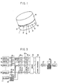
- Fig. 1 illustrates, in perspective, an embodiment of the present invention.
- This embodiment is a rotary head drum unit of the type in which a rotary head is fixed to the upper drum and is driven as a unitary structure therewith through a dynamic tracking actuator (not shown).
- This rotary head drum unit has a plurality of sensors 3, ..., 3 embedded in its lower drum 1 along a virtual lead 2, instead of along the conventional lead, for detecting a position of the lower edge 8 of a tape 4.
- the virtual lead 2 mentioned herein is imaginarily indicative of the position where such tape edge 8 is located during a standard running of the tape 4, and thus corresponds to a position of the lead of a conventional rotary head drum.
- the position sensors 3, ..., 3 are photosensors such as photo-diodes.
- the photosensors 3,..., 3 detect a position of the tape edge 8, sensitive to a light, which is received by them from a light source (not shown) disposed around the drum 1, being changed in quantity by interception of the tape 4, and the surfaces of the photosensors are so treated to be failure- free against sliding thereon of the tape 4 as to avoid any adverse effect upon the tape running behaviour.
- the outputs of the photosensors (light receiving elements) 3, ..., 3 are fed back to the dynamic tracking actuator to control the axial displacement of the rotary head 5; namely, its displacement in the direction of tracking.
- the tracking is carried out to bring the head 5 to a predetermined position; i.e. the position where the tape 4 ought to run along the virtual lead 2, thereby offsetting the deviation of the tape 4 running on the lower drum 1 from the virtual lead 2.
- the dynamic tracking actuator is usually a piezoelectric element, for instance.
- known dynamic tracking heads are disclosed in, for example, the Japanese Pat. Pub. Nos. 56568/87 and 42335/87, the Japanese U.M. Pub. No. 32345/87, etc.
- a drive of the tape 4 therearound along the virtual lead 2 assumable from the photosensors 3, ..., 3 places at work the feedback by those photosensors responsive to a deviation of the tape 4 from the virtual lead 2 (or standard position of the tape in its heightwise direction) to control the dynamic tracking actuator associated with the head 5, whereby the head 5 is to be moved upwardly and downwardly, which can be depicted in Fig. 2B to draw a locus passing through points x where the photosensors are located for detecting purpose.
- the tape 4 shows its run along the virtual lead 2 in such a manner as if it was guided mechanically by a lead.
- Fig. 3 illustrates an embodiment of a control system.
- Each deviation amount occurred by the tape 4 being deviated from the standard height position, which is detected by the respective sensors 3, ..., 3 in the order of discrete values at the respective corresponding points upon the tape, is amplified by means of amplifiers 10 i , 10 2 , 10 3 , ..., 10 N , respectively.
- the thus-amplified outputs, representing the tape deviations, are sampled and held in sample-and-hold circuits 13 1 , 13 2 , 13 3 , ..., 13 N in accordance with a clock which is generated by a clock generator 2 in synchronism with one or two pulses from a drum pulse generator 11, the pulses being produced therefrom per rotation of the rotary head and representing a standard rotation position of the rotary head. Then, such outputs in the sample-and-hold circuits are transformed into digital signals by means of the A/D converters 14 1 , 14 2 , 14 3 , ..., 14 N , and thereafter stored in memory 14.
- a high-order interpolation is performed by a signal processor 16 to produce a control signal for driving the dynamic tracking piezoelectric element.
- the control signal is sent through a D/A converter 17 and a piezoelectric element drive circuit 18 so as to cause the head 5 to move upwardly or downwardly.
- the timing for sampling and holding each sensor output may be delayed according to the actual condition of operation, and in the signal processor 16, may also be employed a linear interpolation or other similar interpolation methods.
- Fig. 4 illustrates another embodiment of the present invention applied to a rotary drum unit of the type in which a rotary head drum 7 is interposed between the upper and lower drums 1 and 6 which are stationary.
- a rotary head drum 7 is interposed between the upper and lower drums 1 and 6 which are stationary.
- the photosensors 3, ..., 3 along virtual lead lines 2 so that a differential output is obtain, using upper and lower edges 8, 8 of the tape to provide for increased accuracy in sensing the position.
- the rotary head 5 is coupled to a rotary head drum 7 through the dynamic tracking actuator.
- the photosensors 3, ..., 3 are embedded in the drums 1 and 6, but his should not be construed as limiting the invention and, though not shown, it is also possible to employ an arrangement wherein position sensors, for example, reflecting type photosensors are disposed outside of the drum 1 or 6 in an opposing relation with the virtual lead 2, and the tape 4 runs in the space between the photosensors 3, ..., 3 and the drums 1, 6.
- Each of the reflecting-type photosensors has a light receiving element and a light emitting element disposed facing toward the boundary between the tape edge 8 and the peripheral surface of the drum in such a manner that the light receiving and emitting elements are axially symmetrical with respect to a line passing through a certain point on the virtual lead 2 and the axis of the drum.
- any variations in reflected light at the boundary between the tape edge 8 and the peripheral surface of the drum are to be sensed by those elements to detect the position of the tape edge 8.
- This arrangement is also applicable to a rotary head drum unit of the type rotating the upper drum 6 in order to permit its detecting the deviation of the tape edge 8 upon the upper drum 6.
- sensors 3, ..., 3, which detect the position of the tape edge may be formed, using MR elements, CCD line sensors or other similar sensors.
- the present invention is particularly suitable for use with a rotary drum unit in a tape drive system which calls for stable tape run and highly accurate formation of track patterns, such as a helical scan type magnetic recording/reproducing device which is used for a thin tape transport or for broadcasting purpose.
Landscapes
- Adjustment Of The Magnetic Head Position Track Following On Tapes (AREA)
Applications Claiming Priority (3)
| Application Number | Priority Date | Filing Date | Title |
|---|---|---|---|
| JP1126666A JPH02306416A (ja) | 1989-05-22 | 1989-05-22 | ヘリカルスキャン型回転ヘッドドラムユニット |
| JP126666/89 | 1989-05-22 | ||
| PCT/JP1990/000652 WO1990014660A1 (en) | 1989-05-22 | 1990-05-22 | Helical scan-type rotary head drum unit |
Publications (3)
| Publication Number | Publication Date |
|---|---|
| EP0425705A1 EP0425705A1 (en) | 1991-05-08 |
| EP0425705A4 EP0425705A4 (en) | 1991-12-18 |
| EP0425705B1 true EP0425705B1 (en) | 1995-02-15 |
Family
ID=14940867
Family Applications (1)
| Application Number | Title | Priority Date | Filing Date |
|---|---|---|---|
| EP90907448A Expired - Lifetime EP0425705B1 (en) | 1989-05-22 | 1990-05-22 | Helical scan-type rotary head drum unit |
Country Status (5)
| Country | Link |
|---|---|
| EP (1) | EP0425705B1 (ko) |
| JP (1) | JPH02306416A (ko) |
| KR (1) | KR0185185B1 (ko) |
| DE (1) | DE69016925T2 (ko) |
| WO (1) | WO1990014660A1 (ko) |
Families Citing this family (1)
| Publication number | Priority date | Publication date | Assignee | Title |
|---|---|---|---|---|
| JP5358602B2 (ja) * | 2011-03-15 | 2013-12-04 | 中国電力株式会社 | 記録計 |
Family Cites Families (4)
| Publication number | Priority date | Publication date | Assignee | Title |
|---|---|---|---|---|
| DE1131421B (de) * | 1952-01-14 | 1962-06-14 | Telefonbau | Anordnung zum absatzweisen Abtasten schraeg zur Bewegungsrichtung eines bandfoermigen Magnetogrammtraegers verlaufender Spuren mittels eines umlaufenden zylindrischen Wandlers |
| GB931752A (en) * | 1960-08-15 | 1963-07-17 | Bush And Rank Cintel Ltd | Improvements in rotary-head magnetic recording and reproducing equipment |
| JPS60115043A (ja) * | 1983-11-26 | 1985-06-21 | Olympus Optical Co Ltd | 磁気記録再生装置 |
| JPS60106233U (ja) * | 1983-12-23 | 1985-07-19 | 富士写真フイルム株式会社 | ビデオテ−プレコ−ダのテ−プセツトセンサ |
-
1989
- 1989-05-22 JP JP1126666A patent/JPH02306416A/ja active Pending
-
1990
- 1990-05-22 DE DE69016925T patent/DE69016925T2/de not_active Expired - Fee Related
- 1990-05-22 KR KR1019900702642A patent/KR0185185B1/ko not_active IP Right Cessation
- 1990-05-22 WO PCT/JP1990/000652 patent/WO1990014660A1/ja active IP Right Grant
- 1990-05-22 EP EP90907448A patent/EP0425705B1/en not_active Expired - Lifetime
Also Published As
| Publication number | Publication date |
|---|---|
| KR0185185B1 (ko) | 1999-05-01 |
| EP0425705A1 (en) | 1991-05-08 |
| EP0425705A4 (en) | 1991-12-18 |
| KR920700444A (ko) | 1992-02-19 |
| DE69016925D1 (de) | 1995-03-23 |
| DE69016925T2 (de) | 1995-06-08 |
| JPH02306416A (ja) | 1990-12-19 |
| WO1990014660A1 (en) | 1990-11-29 |
Similar Documents
| Publication | Publication Date | Title |
|---|---|---|
| US5452152A (en) | Tracking control on longitudinal azimuth tracks using an auxiliary read head | |
| US4982295A (en) | Method for centering a read/write head of a magnetic data storage apparatus on a track of a magnetic disk | |
| US4878135A (en) | Method and system for a magnetic disk drive employing a quadratic compensation function for determining an offset correction value | |
| US4794472A (en) | Video tape reproducing apparatus with a processor that time-shares different operations | |
| JPH0731793B2 (ja) | 磁気テープの異なつたトラツク上に磁気ヘツドを位置決めするための方法および装置 | |
| EP0840292A2 (en) | Track-curvature detection using clock phase shift in azimuth recording | |
| US4167762A (en) | Open loop servo-system for accurate tracking in a video signal reproducing apparatus | |
| EP0037738B1 (en) | Automatic track following feature for helical video recorder | |
| EP0067562B1 (en) | Magnetic reproducing apparatus | |
| EP0425705B1 (en) | Helical scan-type rotary head drum unit | |
| EP0587320B1 (en) | Signal reproducing apparatus | |
| US5119249A (en) | Tracking error detection circuit using pilot signals during tape reproduction | |
| US5373404A (en) | Helical scan type rotary head drum unit | |
| US5241434A (en) | Magnetic recording signal reproducing apparatus | |
| US6356519B1 (en) | Disk apparatus for moving head to center of target track in seek operation | |
| KR100240795B1 (ko) | 트래킹 제어 소자 | |
| US5270529A (en) | Device for sensing rotary head position of magnetic recording and reproducing apparatus | |
| KR930008793A (ko) | 기록 재생 장치 | |
| US4835631A (en) | Apparatus for controlling playback head tracking for rotary recording medium using average peak envelope position | |
| US5126894A (en) | Servo circuit for capstan motor | |
| US5331480A (en) | Dynamic tracking reproduction apparatus | |
| US5412520A (en) | Tracking control which avoids lock-up for rotary head reproducing apparatus and which senses whether a trucking control signal is absent for a predetermined time | |
| JPH0744841A (ja) | 回転ヘッド型磁気記録再生装置 | |
| KR930008492B1 (ko) | 광 디스크장치의 고속위치설정 서보시스템 | |
| JPH04368607A (ja) | 磁気記録再生装置 |
Legal Events
| Date | Code | Title | Description |
|---|---|---|---|
| PUAI | Public reference made under article 153(3) epc to a published international application that has entered the european phase |
Free format text: ORIGINAL CODE: 0009012 |
|
| 17P | Request for examination filed |
Effective date: 19910211 |
|
| AK | Designated contracting states |
Kind code of ref document: A1 Designated state(s): DE FR GB |
|
| A4 | Supplementary search report drawn up and despatched |
Effective date: 19911030 |
|
| AK | Designated contracting states |
Kind code of ref document: A4 Designated state(s): DE FR GB |
|
| 17Q | First examination report despatched |
Effective date: 19931207 |
|
| GRAA | (expected) grant |
Free format text: ORIGINAL CODE: 0009210 |
|
| AK | Designated contracting states |
Kind code of ref document: B1 Designated state(s): DE FR GB |
|
| REF | Corresponds to: |
Ref document number: 69016925 Country of ref document: DE Date of ref document: 19950323 |
|
| ET | Fr: translation filed | ||
| PLBE | No opposition filed within time limit |
Free format text: ORIGINAL CODE: 0009261 |
|
| STAA | Information on the status of an ep patent application or granted ep patent |
Free format text: STATUS: NO OPPOSITION FILED WITHIN TIME LIMIT |
|
| 26N | No opposition filed | ||
| REG | Reference to a national code |
Ref country code: GB Ref legal event code: 732E |
|
| REG | Reference to a national code |
Ref country code: FR Ref legal event code: TP |
|
| PGFP | Annual fee paid to national office [announced via postgrant information from national office to epo] |
Ref country code: FR Payment date: 19980511 Year of fee payment: 9 |
|
| PGFP | Annual fee paid to national office [announced via postgrant information from national office to epo] |
Ref country code: GB Payment date: 19980513 Year of fee payment: 9 |
|
| PGFP | Annual fee paid to national office [announced via postgrant information from national office to epo] |
Ref country code: DE Payment date: 19980529 Year of fee payment: 9 |
|
| PG25 | Lapsed in a contracting state [announced via postgrant information from national office to epo] |
Ref country code: GB Free format text: LAPSE BECAUSE OF NON-PAYMENT OF DUE FEES Effective date: 19990522 |
|
| GBPC | Gb: european patent ceased through non-payment of renewal fee |
Effective date: 19990522 |
|
| PG25 | Lapsed in a contracting state [announced via postgrant information from national office to epo] |
Ref country code: FR Free format text: LAPSE BECAUSE OF NON-PAYMENT OF DUE FEES Effective date: 20000131 |
|
| PG25 | Lapsed in a contracting state [announced via postgrant information from national office to epo] |
Ref country code: DE Free format text: LAPSE BECAUSE OF NON-PAYMENT OF DUE FEES Effective date: 20000301 |
|
| REG | Reference to a national code |
Ref country code: FR Ref legal event code: ST |