EP0425274A2 - Trennbarer Strichkodeleser - Google Patents
Trennbarer Strichkodeleser Download PDFInfo
- Publication number
- EP0425274A2 EP0425274A2 EP90311666A EP90311666A EP0425274A2 EP 0425274 A2 EP0425274 A2 EP 0425274A2 EP 90311666 A EP90311666 A EP 90311666A EP 90311666 A EP90311666 A EP 90311666A EP 0425274 A2 EP0425274 A2 EP 0425274A2
- Authority
- EP
- European Patent Office
- Prior art keywords
- scanning
- unit
- light
- bar code
- window
- Prior art date
- Legal status (The legal status is an assumption and is not a legal conclusion. Google has not performed a legal analysis and makes no representation as to the accuracy of the status listed.)
- Granted
Links
Images


Classifications
-
- G—PHYSICS
- G06—COMPUTING; CALCULATING OR COUNTING
- G06K—GRAPHICAL DATA READING; PRESENTATION OF DATA; RECORD CARRIERS; HANDLING RECORD CARRIERS
- G06K7/00—Methods or arrangements for sensing record carriers, e.g. for reading patterns
- G06K7/10—Methods or arrangements for sensing record carriers, e.g. for reading patterns by electromagnetic radiation, e.g. optical sensing; by corpuscular radiation
- G06K7/10544—Methods or arrangements for sensing record carriers, e.g. for reading patterns by electromagnetic radiation, e.g. optical sensing; by corpuscular radiation by scanning of the records by radiation in the optical part of the electromagnetic spectrum
- G06K7/10821—Methods or arrangements for sensing record carriers, e.g. for reading patterns by electromagnetic radiation, e.g. optical sensing; by corpuscular radiation by scanning of the records by radiation in the optical part of the electromagnetic spectrum further details of bar or optical code scanning devices
- G06K7/10861—Methods or arrangements for sensing record carriers, e.g. for reading patterns by electromagnetic radiation, e.g. optical sensing; by corpuscular radiation by scanning of the records by radiation in the optical part of the electromagnetic spectrum further details of bar or optical code scanning devices sensing of data fields affixed to objects or articles, e.g. coded labels
- G06K7/10871—Methods or arrangements for sensing record carriers, e.g. for reading patterns by electromagnetic radiation, e.g. optical sensing; by corpuscular radiation by scanning of the records by radiation in the optical part of the electromagnetic spectrum further details of bar or optical code scanning devices sensing of data fields affixed to objects or articles, e.g. coded labels randomly oriented data-fields, code-marks therefore, e.g. concentric circles-code
-
- G—PHYSICS
- G06—COMPUTING; CALCULATING OR COUNTING
- G06K—GRAPHICAL DATA READING; PRESENTATION OF DATA; RECORD CARRIERS; HANDLING RECORD CARRIERS
- G06K7/00—Methods or arrangements for sensing record carriers, e.g. for reading patterns
- G06K7/10—Methods or arrangements for sensing record carriers, e.g. for reading patterns by electromagnetic radiation, e.g. optical sensing; by corpuscular radiation
- G06K7/10544—Methods or arrangements for sensing record carriers, e.g. for reading patterns by electromagnetic radiation, e.g. optical sensing; by corpuscular radiation by scanning of the records by radiation in the optical part of the electromagnetic spectrum
- G06K7/10821—Methods or arrangements for sensing record carriers, e.g. for reading patterns by electromagnetic radiation, e.g. optical sensing; by corpuscular radiation by scanning of the records by radiation in the optical part of the electromagnetic spectrum further details of bar or optical code scanning devices
- G06K7/10881—Methods or arrangements for sensing record carriers, e.g. for reading patterns by electromagnetic radiation, e.g. optical sensing; by corpuscular radiation by scanning of the records by radiation in the optical part of the electromagnetic spectrum further details of bar or optical code scanning devices constructional details of hand-held scanners
- G06K7/109—Methods or arrangements for sensing record carriers, e.g. for reading patterns by electromagnetic radiation, e.g. optical sensing; by corpuscular radiation by scanning of the records by radiation in the optical part of the electromagnetic spectrum further details of bar or optical code scanning devices constructional details of hand-held scanners adaptations to make the hand-held scanner useable as a fixed scanner
Definitions
- the present invention relates to a bar code reader for reading bar codes printed on packages or labels of goods, and more particularly to a separate-type bar code reader comprising a main body and a sub-body detachably mounted on the main body for use as a stationary bar code reader or a hand-held bar code reader.
- POS point-of-sale
- a POS system comprises a bar code reader for reading bar codes attached to products by scanning them with a laser light beam for conversion to a form of information suitable for computational processing, a computer for processing the resulting information, and an electronic cash register coupled between the reader and the computer for outputting information for the customer.
- Bar-code readers include the stationary type which requires the goods to be moved relative to the reader, the hand-held type.
- the hand-held type includes the touch type, the pen type, the gun type, etc., which can be moved relative to the goods.
- the stationary bar code reader or the hand-held bar code reader is used according to the size and weight of the goods.
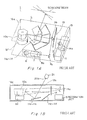
- FIG. 1A is a perspective view illustrating the interior of a conventional stationary-type bar code reader and Figure 1B is its side view.
- the stationary reader includes an optical unit 4 and a recognition unit 5.
- the optical unit 4 has the following functions: a bar code scanning function in which outgoing light from a light-beam-producing unit 8a, comprised of a light source 6 formed of, for example, a laser diode and a beam shaping lens 7, is reflected by plane mirrors 9a and 9b to a rotating polygonal mirror 10a and the reflected light from the polygonal mirror 10a is then reflected by scanning-pattern-forming mirrors 11a to 11f to produce light beams which scan a bar code 20a of a product 2a at different angles through a reading window 12a; and a photoelectric conversion function of gathering reflected light from the bar code 20a on the product 2a through the polygonal mirror 10a and the condenser lens 13 and receiving it with an optical sensor 14a for conversion to an electrical signal.
- the polygonal mirror 10a has six reflecting surfaces and makes six scans per rotation.
- the reflecting surfaces of the mirror are formed vertically at different angles to produce scanning beams in different directions.
- the polygonal mirror 10a is rotated by a motor M1.
- the motor M1, the light source 6 and the optical sensor 14a are driven by a control unit 15.
- the recognition unit 5 recognizes an electrical signal from the optical sensor 14a as a bar code signal through an analog to digital converter (not shown) and a demodulator (not shown).
- the optical unit 4 and the recognition unit 5 are housed in a casing 16a.
- the bar code 20a is formed of alternate black and white printed stripes of different widths, as shown in Figure 2, and a character, a digit, a symbol or the like is represented by the permutation of a predetermined number of stripes.
- the bar code 20a When the product 2a is moved over the reading window 12a with the bar code 20a set downward while the scanning beams emerge from the reading window 12a under the control of the control unit 15 as shown in Figures 1A, and 1B, the bar code is scanned by the beams and recognized as data by the recognition unit 5 after conversion of the reflected light therefrom to an electrical signal by the optical sensor 14a.
- the stationary-type bar code reader is used where a product 2a is so small that an operator can move it over the reading window 12a with one hand and the reader can read the bar code correctly irrespective of its orientation. That is, the scanning-pattern-forming mirrors 11a to 11f enable the bar code 20a of the product 2a to be read irrespective of its orientation.
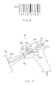
- FIG 3 is a side view of a gun-type bar code reader.
- the gun-type bar code reader comprises a light-producing unit 8b consisting of a light source 6a of a laser diode and a beam-shaping lens 7a, a plane mirror 9c, a polygonal mirror 10b driven by a motor M2, a scanning window 18a, a condenser lens 13a and an optical sensor 14b.
- outgoing light from the light outputting unit 8b is reflected by the plane mirror 9c toward the polygonal mirror 10b and then radiated from the scanning window 18a to the outside as scanning beams.
- the scanning window close to the bar code 20a printed on a product 2a
- the bar code is scanned by the scanning beams.
- the reflected light from the bar code is gathered by the condenser lens 13a via the polygonal mirror 10b and then received by the optical sensor 14b for conversion to an electrical signal which is in turn applied to the external recognition unit (not shown).
- the gun type reader 1a is used when the stationary reader 1 is difficult to use, e.g., where a product 2a is large or heavy or where there are a number of products even if they are small. With the gun type reader, however, since the scanning beams are oriented in one direction, the bar code 20a must be read in this direction.
- One object of the present invention is to provide a bar code reader which has high operability.
- Another object of the present invention is to provide a separate-type bar code reader which is adapted for use as a stationary-type bar code reader when a product is small and light and as a hand-held bar code reader when a product is large or heavy.
- a further object of the present invention is to provide an economical bar code reader which eliminates the need for both a stationary-type reader and a hand-held reader.
- FIG 4 illustrates the basic arrangement of the separate-type bar code reader of the present invention.
- the separate-type bar code reader of the present invention comprises a main body 16 and a separable sub-body 17 which is detachably mounted on the main body 16.
- the sub-body 17 comprises a light-emitting unit 8 for emitting light, a scanning unit 10 for reflecting the outgoing light from the light-emitting unit 8 to produce a scanning beam, a scanning window 18 for emitting the scanning beam from the scanning unit 10 to the outside, and a conversion unit 14 for receiving light reflected from a bar code 20 printed on an object 2 resulting from a scanning with the scanning beam, and converting the received light to an electrical signal.
- the main body 16 comprises a mounting portion 19 on which the sub-body is detachably mounted, a light-receiving window 21 for receiving the scanning beam emitted through the scanning window 18 of the sub-body 17 mounted on the mounting portion 19, a scanning-pattern-forming mirror unit 11 for forming a scanning beam of a plurality of patterns from the scanning beam received through the light-receiving window 21, and a reading window 12 for transmitting the plural-pattern scanning beams formed by the scanning-pattern-forming mirror unit 11 to the outside.
- the scanning beams of different patterns formed by the scanning-pattern- forming mirror unit 11 are directed onto the bar code through the reading window 12, and the reflected light from the bar code is received by the conversion unit 14 through the reading window 12, the light-receiving window 21, the scanning window 18, etc.
- the scanning beam generated by the scanning unit 10 is directed onto the bar code 20 and the light reflected therefrom is received by the conversion unit 14 through the scanning window 18, etc.
- the scanning beams are of different patterns and are patterned so that they intersect one another. It is desired that one or more scanning beams should cross the bar code 20 irrespective of its orientation. If this occurs, non-directional reading of bar codes is realized.
- the scanning unit 10 can be realized by rotating a polygonal mirror with reflecting surfaces formed at different angles.
- the scanning-pattern-forming mirror unit 11 can be realized by disposing a plurality of mirrors in different positions at different inclinations. Thus, a scanning beam of a different pattern is produced each time the scanning beam from the scanning unit 10 crosses a mirror.
- Scanning beams of different patterns may be formed by the scanning unit 10 of the sub-body 17 in place of the scanning-pattern-forming unit 11 of the main body 16.
- the main body 16 naturally has no need of the scanning-pattern-forming mirror 11 and has only to be provided with a single mirror for directing scanning beams of different patterns received through the light-receiving window 21 to the reading window 12.
- a scanning beam is transmitted from the sub-body 17 to the main body 16 through the scanning window 18 and light-receiving window 21 so that scanning beams of different patterns are formed by the scanning-pattern-forming mirror unit 11 and then directed onto the bar code 20 printed on the external object 2 through the reading window 12.
- the light reflected from the bar code is converted by the conversion unit 14 to an electrical signal so that data represented by the bar code is read.
- the scanning window 18 of the sub-body 17 is brought near the bar code 20 printed on the object 2 so that the bar code is irradiated by the scanning beam through the scanning window 18 and the light reflected therefrom is converted to an electrical signal to be thereby read as bar code data 20.
- the sub-body 17 may be mounted on the main body 16 for use as a stationary-type reader.
- the sub-body 17 can be removed from the mounting portion 19 of the main body 16 for use as a hand-held reader. Therefore, there is no necessity for a stationary reader and a hand reader to be equipped separately.
- the separate-type bar code reader of the present invention is thus economical.
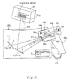
- Figure 5 is a side view and Figure 6 is a perspective view of a bar code reader embodying the present invention.
- the same reference numbers represent the same elements in all the drawings.
- a product 2a, a polygonal mirror 10b, an optical sensor 14b and a stationary unit 16b correspond to the object 2, the scanning unit 10, the conversion unit 14 and the main body 16 of Figure 4, respectively.
- the bar code reader of this embodiment is comprised of a stationary unit 16b and a separation unit 17a.
- the separation unit 17a is detachably mounted on the stationary unit 16b through a mounting portion 19a.
- the separation unit 17a comprises a light-outputting unit 8b constructed from a light source 6a of a laser diode and a beam-shaping lens 7a, a mirror 9c, a polygonal mirror 10b rotated by a motor M2, a scanning window 18a, a condenser lens 13a and an optical sensor 14b.
- the stationary unit 16b is provided with the mounting portion 19a on which the head of the separation unit 17a is detachably mounted.
- the mounting portion 19a is provided with two protruding guides 17b.
- the separation unit 17a fits between the guides 17b.
- a light-receiving window 21a for directing a scanning beam emitted from the inside of the separation unit 17a through the scanning window 18a to the inside of the stationary unit 16b when the separation unit 17a is mounted on the mounting portion 19a.
- the light-receiving window 21a and the scanning window 18a are covered with a transparent member, such as a glass sheet, thereby preventing dust or dirt from entering the stationary unit 16b and the separation unit 17a.
- a reading window 12a On the upper surface of the stationary unit 16b is provided a reading window 12a covered with a transparent member, such as a glass sheet, which can transmit a scanning beam.
- a scanning-pattern-forming mirror unit 11 which forms scanning beams of different patterns from an incident scanning beam transmitted through the light-receiving window 21a. The resulting scanning beams of different patterns are directed to the outside through the reading window 12a.
- the scanning-pattern-forming mirror unit 11 is comprised of a plurality of mirrors 11a through 11f (six in the figure), disposed in their respective locations at different inclinations. When an incident scanning beam crosses the mirrors in sequence, new scanning beams of different patterns are formed.
- the resulting scanning beams should have patterns which intersect with one another on the surface of the reading window 12a and one or more scanning beams may be able to scan the bar code 2a when it is placed at any direction over the reading window 12a.
- An example of such patterns of the scanning beams is illustrated in Figure 7. This Figure indicates linear patterns formed by the scanning beams when they cross the surface S1 of the reading window 12a and a virtual plane S2 normal to the surface S1.
- the stationary unit 16b incorporates a recognition unit 5 which recognizes an electrical signal output from the optical sensor 14b of the separation unit 17a as bar code data.
- the electrical signal is fed to the recognition unit 5 via a cable 22 connected between the separation unit 17a and the stationary unit 16b.
- the separation unit 17a can be mounted on the stationary unit 16b for use as a stationary-type bar code reader for a product 2a which is small or light enough to allow an operator to move it with one hand, with the bar code 20a directed toward the reading window 12a.
- light from the light-outputting unit 8b of the separation unit 17a is reflected by the mirror 9c and the polygonal mirror 10b to form a scanning beam.
- the scanning beam is transmitted into the stationary unit 16b through the scanning window 18a and the light-receiving window 21a.
- the scanning-pattern-forming mirror unit 11 It is then reflected by the scanning-pattern-forming mirror unit 11 to form scanning beams of different patterns, which are then transmitted to the outside through the reading window 12a to thereby scan the bar code 20a of the product 2a.
- Part of the light reflected from the bar code follows the reverse path of the scanning beam, that is, it falls onto the polygonal mirror 10b through the reading window 12a, the scanning-pattern-forming mirror unit 11, the light-receiving window 21a and the scanning window 18a, and the light reflected from the polygonal mirror 10b is received by the optical sensor 14b through the condenser lens 13a and is then converted to an electrical signal.
- the electrical signal is fed to the recognition unit 5 via the cable 22 to be read as bar code data.
- the separation unit 17a is removed from the mounting portion 19 for use a hand type reader.
- the scanning window 18a of the separation unit 17a is held near the bar code 20a printed on the product 2a so that the bar code is scanned by the scanning beam from the scanning window 18a.
- Part of the light reflected from the bar code is received by the optical sensor 14b through the scanning window 18a, the polygonal mirror 10b and the condenser lens 13a for conversion to an electrical signal.
- the electrical signal is fed to the recognition unit 5 to be read as bar code data.
- the reader of the present invention can be used properly as a stationary-type or a hand-held reader according to the size or weight of a product. This is very economical because two different types of readers need not be equipped separately.
- the forms of the main body 16 (stationary unit 16b) and the separation unit 17 (17b) are not limited to those of the embodiment described. Various forms may be adopted. In particular, the separation unit 17 (17b) need not be of the gun type. Any form can be adopted providing it is easy for an operator to hold and operate.
- the structure of the mounting portion 19 (19a) may also be modified variously, providing the separation unit 17 (17b) can be securely mounted on the main body 16 (stationary unit 16b).
- the separation unit 17 may be mounted on the main body 16 for use as a stationary type reader where a product is of a size or weight which allows an operator to perform a read operation on its bar code using one hand.
- the scanning unit 10 also performs the same function as the scanning-pattern-forming mirror unit 11, the scanning-pattern-forming mirror unit 11 is not provided in the main body 16.
- the separation unit 17 is removed from the main body 16 for use as a hand-held reader. This will improve the work efficiency of the operator.
- it is economical because a stationary-type bar code reader and a hand-held bar code reader need not be equipped separately.
Landscapes
- Physics & Mathematics (AREA)
- Engineering & Computer Science (AREA)
- Electromagnetism (AREA)
- Health & Medical Sciences (AREA)
- General Health & Medical Sciences (AREA)
- Toxicology (AREA)
- Artificial Intelligence (AREA)
- Computer Vision & Pattern Recognition (AREA)
- General Physics & Mathematics (AREA)
- Theoretical Computer Science (AREA)
- Mechanical Optical Scanning Systems (AREA)
- Cash Registers Or Receiving Machines (AREA)
Applications Claiming Priority (2)
| Application Number | Priority Date | Filing Date | Title |
|---|---|---|---|
| JP277589/89 | 1989-10-25 | ||
| JP1277589A JP2808735B2 (ja) | 1989-10-25 | 1989-10-25 | 分離型読取装置 |
Publications (3)
| Publication Number | Publication Date |
|---|---|
| EP0425274A2 true EP0425274A2 (de) | 1991-05-02 |
| EP0425274A3 EP0425274A3 (en) | 1993-06-09 |
| EP0425274B1 EP0425274B1 (de) | 1996-09-18 |
Family
ID=17585567
Family Applications (1)
| Application Number | Title | Priority Date | Filing Date |
|---|---|---|---|
| EP90311666A Expired - Lifetime EP0425274B1 (de) | 1989-10-25 | 1990-10-24 | Trennbarer Strichkodeleser |
Country Status (4)
| Country | Link |
|---|---|
| EP (1) | EP0425274B1 (de) |
| JP (1) | JP2808735B2 (de) |
| KR (1) | KR930006798B1 (de) |
| DE (1) | DE69028594T2 (de) |
Cited By (11)
| Publication number | Priority date | Publication date | Assignee | Title |
|---|---|---|---|---|
| EP0615207A2 (de) * | 1993-03-08 | 1994-09-14 | Symbol Technologies, Inc. | Vorrichtung zum selbststätigen Festhalten und zur Betreibung eines tragbaren Laserlesers |
| EP0490605B1 (de) * | 1990-12-10 | 1996-04-17 | Ncr International Inc. | Optischer Abtastapparat zum Lesen von verschlüsselten Symbolen |
| EP0490601B1 (de) * | 1990-12-10 | 1996-04-17 | Ncr International Inc. | Optischer Abtastapparat zum Lesen von verschlüsselten Symbolen |
| EP0490603B1 (de) * | 1990-12-10 | 1996-04-17 | Ncr International Inc. | Optischer Abtastapparat zum Lesen von verschlüsselten Symbolen |
| EP0490602B1 (de) * | 1990-12-10 | 1996-08-21 | Ncr International Inc. | Optischer Abtastapparat zum Lesen von verschlüsselten Symbolen |
| US5691528A (en) * | 1989-10-30 | 1997-11-25 | Symbol Technologies Inc. | Scanning system for either hand-held or stationary operation for reading 1-D or 2-D barcodes |
| US5744790A (en) * | 1996-01-25 | 1998-04-28 | Symbol Technologies, Inc. | Split optics focusing apparatus for CCD-based bar code scanner |
| US5821524A (en) * | 1996-08-19 | 1998-10-13 | Pharmacopeia, Inc. | Method and apparatus for reading bar coded tubular members such as cylindrical vials |
| EP1310903A1 (de) * | 1993-11-17 | 2003-05-14 | Symbol Technologies, Inc. | Kompakter Strichcodeabtaster mit Stossschutz |
| EP2202667A1 (de) * | 2008-12-18 | 2010-06-30 | NCR Corporation | Strichcode-Lesestation |
| CN102945357A (zh) * | 2011-06-21 | 2013-02-27 | Ncr公司 | 光码扫描器 |
Citations (2)
| Publication number | Priority date | Publication date | Assignee | Title |
|---|---|---|---|---|
| US4694182A (en) * | 1986-02-27 | 1987-09-15 | Spectra-Physics, Inc. | Hand held bar code reader with modulated laser diode and detector |
| US4766297A (en) * | 1987-01-08 | 1988-08-23 | Recognition Equipment Incorporated | Dual mode stationary and portable scanning system |
Family Cites Families (1)
| Publication number | Priority date | Publication date | Assignee | Title |
|---|---|---|---|---|
| JPS54170742U (de) * | 1978-05-23 | 1979-12-03 |
-
1989
- 1989-10-25 JP JP1277589A patent/JP2808735B2/ja not_active Expired - Fee Related
-
1990
- 1990-10-24 DE DE69028594T patent/DE69028594T2/de not_active Expired - Fee Related
- 1990-10-24 EP EP90311666A patent/EP0425274B1/de not_active Expired - Lifetime
- 1990-10-25 KR KR1019900017129A patent/KR930006798B1/ko not_active IP Right Cessation
Patent Citations (2)
| Publication number | Priority date | Publication date | Assignee | Title |
|---|---|---|---|---|
| US4694182A (en) * | 1986-02-27 | 1987-09-15 | Spectra-Physics, Inc. | Hand held bar code reader with modulated laser diode and detector |
| US4766297A (en) * | 1987-01-08 | 1988-08-23 | Recognition Equipment Incorporated | Dual mode stationary and portable scanning system |
Cited By (14)
| Publication number | Priority date | Publication date | Assignee | Title |
|---|---|---|---|---|
| US5691528A (en) * | 1989-10-30 | 1997-11-25 | Symbol Technologies Inc. | Scanning system for either hand-held or stationary operation for reading 1-D or 2-D barcodes |
| EP0490605B1 (de) * | 1990-12-10 | 1996-04-17 | Ncr International Inc. | Optischer Abtastapparat zum Lesen von verschlüsselten Symbolen |
| EP0490601B1 (de) * | 1990-12-10 | 1996-04-17 | Ncr International Inc. | Optischer Abtastapparat zum Lesen von verschlüsselten Symbolen |
| EP0490603B1 (de) * | 1990-12-10 | 1996-04-17 | Ncr International Inc. | Optischer Abtastapparat zum Lesen von verschlüsselten Symbolen |
| EP0490602B1 (de) * | 1990-12-10 | 1996-08-21 | Ncr International Inc. | Optischer Abtastapparat zum Lesen von verschlüsselten Symbolen |
| EP0615207A3 (de) * | 1993-03-08 | 1998-07-01 | Symbol Technologies, Inc. | Vorrichtung zum selbststätigen Festhalten und zur Betreibung eines tragbaren Laserlesers |
| EP0615207A2 (de) * | 1993-03-08 | 1994-09-14 | Symbol Technologies, Inc. | Vorrichtung zum selbststätigen Festhalten und zur Betreibung eines tragbaren Laserlesers |
| EP1310903A1 (de) * | 1993-11-17 | 2003-05-14 | Symbol Technologies, Inc. | Kompakter Strichcodeabtaster mit Stossschutz |
| US5744790A (en) * | 1996-01-25 | 1998-04-28 | Symbol Technologies, Inc. | Split optics focusing apparatus for CCD-based bar code scanner |
| US5821524A (en) * | 1996-08-19 | 1998-10-13 | Pharmacopeia, Inc. | Method and apparatus for reading bar coded tubular members such as cylindrical vials |
| EP2202667A1 (de) * | 2008-12-18 | 2010-06-30 | NCR Corporation | Strichcode-Lesestation |
| US8113429B2 (en) | 2008-12-18 | 2012-02-14 | Ncr Corporation | Barcode reading station |
| CN102945357A (zh) * | 2011-06-21 | 2013-02-27 | Ncr公司 | 光码扫描器 |
| CN102945357B (zh) * | 2011-06-21 | 2015-11-18 | Ncr公司 | 光码扫描器及在光码扫描器中读取条码的方法 |
Also Published As
| Publication number | Publication date |
|---|---|
| JPH03138788A (ja) | 1991-06-13 |
| DE69028594T2 (de) | 1997-01-30 |
| EP0425274B1 (de) | 1996-09-18 |
| KR930006798B1 (ko) | 1993-07-23 |
| KR910008607A (ko) | 1991-05-31 |
| DE69028594D1 (de) | 1996-10-24 |
| EP0425274A3 (en) | 1993-06-09 |
| JP2808735B2 (ja) | 1998-10-08 |
Similar Documents
| Publication | Publication Date | Title |
|---|---|---|
| US5314631A (en) | Stationary bar code reader which can be detected and separated into a hand-held bar code reader | |
| US5206491A (en) | Plural beam, plural window multi-direction bar code reading device | |
| EP0122126B1 (de) | Lichtbündel-Abtastapparat | |
| US6330974B1 (en) | High resolution laser imager for low contrast symbology | |
| US4766297A (en) | Dual mode stationary and portable scanning system | |
| US4935610A (en) | Hand-held bar code reader | |
| US5216233A (en) | Versatile RF terminal-scanner system | |
| US5262628A (en) | Narrow-bodied, single- and twin-windowed portable laser scanning head for reading bar code symbols | |
| US5479002A (en) | Bar code scanner with scanning beam and/or field of view adjustable about three mutually orthogonal axes | |
| US5214270A (en) | Modular handheld or fixed scanner | |
| EP0535905A1 (de) | Optische Abtasteinrichtung | |
| US6840453B2 (en) | Optical scanning apparatus | |
| EP0425274A2 (de) | Trennbarer Strichkodeleser | |
| US5149949A (en) | Optical scanner with counterrotating reflector elements | |
| EP0996077B1 (de) | Optische Abtasteinrichtung, Kodeleser und Strichkodeleser mit erhöhtem Freiheitsgrad zur Positionierung von optischen Bauteilen | |
| EP0318574B1 (de) | Optisches ablesegerät | |
| EP0396485B1 (de) | Strichkodeleser mit grosser Schärfentiefe | |
| US5179271A (en) | Compact optical scan pattern generator for bar code reading systems | |
| US7552874B2 (en) | Optical scanner | |
| EP0414452B1 (de) | Handführbarer Strichcodeleser | |
| JPH04302069A (ja) | 多重焦点走査システム | |
| US5223700A (en) | Bar code reader having a polygon mirror providing different scan line lengths | |
| EP0373934A2 (de) | Handlesegerät für Strichkodes | |
| EP0490602B1 (de) | Optischer Abtastapparat zum Lesen von verschlüsselten Symbolen | |
| CA2020540C (en) | Bar code reader |
Legal Events
| Date | Code | Title | Description |
|---|---|---|---|
| PUAI | Public reference made under article 153(3) epc to a published international application that has entered the european phase |
Free format text: ORIGINAL CODE: 0009012 |
|
| AK | Designated contracting states |
Kind code of ref document: A2 Designated state(s): DE FR GB |
|
| PUAL | Search report despatched |
Free format text: ORIGINAL CODE: 0009013 |
|
| AK | Designated contracting states |
Kind code of ref document: A3 Designated state(s): DE FR GB |
|
| 17P | Request for examination filed |
Effective date: 19931202 |
|
| 17Q | First examination report despatched |
Effective date: 19941102 |
|
| GRAH | Despatch of communication of intention to grant a patent |
Free format text: ORIGINAL CODE: EPIDOS IGRA |
|
| GRAH | Despatch of communication of intention to grant a patent |
Free format text: ORIGINAL CODE: EPIDOS IGRA |
|
| GRAA | (expected) grant |
Free format text: ORIGINAL CODE: 0009210 |
|
| AK | Designated contracting states |
Kind code of ref document: B1 Designated state(s): DE FR GB |
|
| REF | Corresponds to: |
Ref document number: 69028594 Country of ref document: DE Date of ref document: 19961024 |
|
| ET | Fr: translation filed | ||
| PLBE | No opposition filed within time limit |
Free format text: ORIGINAL CODE: 0009261 |
|
| STAA | Information on the status of an ep patent application or granted ep patent |
Free format text: STATUS: NO OPPOSITION FILED WITHIN TIME LIMIT |
|
| 26N | No opposition filed | ||
| REG | Reference to a national code |
Ref country code: GB Ref legal event code: IF02 |
|
| PGFP | Annual fee paid to national office [announced via postgrant information from national office to epo] |
Ref country code: GB Payment date: 20051019 Year of fee payment: 16 |
|
| PGFP | Annual fee paid to national office [announced via postgrant information from national office to epo] |
Ref country code: DE Payment date: 20051020 Year of fee payment: 16 |
|
| PG25 | Lapsed in a contracting state [announced via postgrant information from national office to epo] |
Ref country code: DE Free format text: LAPSE BECAUSE OF NON-PAYMENT OF DUE FEES Effective date: 20070501 |
|
| GBPC | Gb: european patent ceased through non-payment of renewal fee |
Effective date: 20061024 |
|
| PG25 | Lapsed in a contracting state [announced via postgrant information from national office to epo] |
Ref country code: GB Free format text: LAPSE BECAUSE OF NON-PAYMENT OF DUE FEES Effective date: 20061024 |
|
| REG | Reference to a national code |
Ref country code: FR Ref legal event code: ST Effective date: 20080630 |
|
| PGFP | Annual fee paid to national office [announced via postgrant information from national office to epo] |
Ref country code: FR Payment date: 20061010 Year of fee payment: 17 |
|
| PG25 | Lapsed in a contracting state [announced via postgrant information from national office to epo] |
Ref country code: FR Free format text: LAPSE BECAUSE OF NON-PAYMENT OF DUE FEES Effective date: 20071031 |