EP0425069B1 - Procédé pour connecter des fils aux serre-câbles ayant des languettes et pour découper ces fils - Google Patents
Procédé pour connecter des fils aux serre-câbles ayant des languettes et pour découper ces fils Download PDFInfo
- Publication number
- EP0425069B1 EP0425069B1 EP90304695A EP90304695A EP0425069B1 EP 0425069 B1 EP0425069 B1 EP 0425069B1 EP 90304695 A EP90304695 A EP 90304695A EP 90304695 A EP90304695 A EP 90304695A EP 0425069 B1 EP0425069 B1 EP 0425069B1
- Authority
- EP
- European Patent Office
- Prior art keywords
- coil lead
- terminal
- wire segment
- wire
- tang
- Prior art date
- Legal status (The legal status is an assumption and is not a legal conclusion. Google has not performed a legal analysis and makes no representation as to the accuracy of the status listed.)
- Expired - Lifetime
Links
Images


Classifications
-
- H—ELECTRICITY
- H02—GENERATION; CONVERSION OR DISTRIBUTION OF ELECTRIC POWER
- H02K—DYNAMO-ELECTRIC MACHINES
- H02K15/00—Methods or apparatus specially adapted for manufacturing, assembling, maintaining or repairing of dynamo-electric machines
- H02K15/08—Forming windings by laying conductors into or around core parts
- H02K15/095—Forming windings by laying conductors into or around core parts by laying conductors around salient poles
-
- H—ELECTRICITY
- H01—ELECTRIC ELEMENTS
- H01R—ELECTRICALLY-CONDUCTIVE CONNECTIONS; STRUCTURAL ASSOCIATIONS OF A PLURALITY OF MUTUALLY-INSULATED ELECTRICAL CONNECTING ELEMENTS; COUPLING DEVICES; CURRENT COLLECTORS
- H01R43/00—Apparatus or processes specially adapted for manufacturing, assembling, maintaining, or repairing of line connectors or current collectors or for joining electric conductors
-
- H—ELECTRICITY
- H02—GENERATION; CONVERSION OR DISTRIBUTION OF ELECTRIC POWER
- H02K—DYNAMO-ELECTRIC MACHINES
- H02K15/00—Methods or apparatus specially adapted for manufacturing, assembling, maintaining or repairing of dynamo-electric machines
- H02K15/0056—Manufacturing winding connections
-
- H—ELECTRICITY
- H02—GENERATION; CONVERSION OR DISTRIBUTION OF ELECTRIC POWER
- H02K—DYNAMO-ELECTRIC MACHINES
- H02K15/00—Methods or apparatus specially adapted for manufacturing, assembling, maintaining or repairing of dynamo-electric machines
- H02K15/0056—Manufacturing winding connections
- H02K15/0068—Connecting winding sections; Forming leads; Connecting leads to terminals
-
- H—ELECTRICITY
- H02—GENERATION; CONVERSION OR DISTRIBUTION OF ELECTRIC POWER
- H02K—DYNAMO-ELECTRIC MACHINES
- H02K3/00—Details of windings
- H02K3/46—Fastening of windings on the stator or rotor structure
- H02K3/52—Fastening salient pole windings or connections thereto
- H02K3/521—Fastening salient pole windings or connections thereto applicable to stators only
- H02K3/522—Fastening salient pole windings or connections thereto applicable to stators only for generally annular cores with salient poles
-
- Y—GENERAL TAGGING OF NEW TECHNOLOGICAL DEVELOPMENTS; GENERAL TAGGING OF CROSS-SECTIONAL TECHNOLOGIES SPANNING OVER SEVERAL SECTIONS OF THE IPC; TECHNICAL SUBJECTS COVERED BY FORMER USPC CROSS-REFERENCE ART COLLECTIONS [XRACs] AND DIGESTS
- Y10—TECHNICAL SUBJECTS COVERED BY FORMER USPC
- Y10T—TECHNICAL SUBJECTS COVERED BY FORMER US CLASSIFICATION
- Y10T29/00—Metal working
- Y10T29/49—Method of mechanical manufacture
- Y10T29/49002—Electrical device making
- Y10T29/49009—Dynamoelectric machine
- Y10T29/49011—Commutator or slip ring assembly
-
- Y—GENERAL TAGGING OF NEW TECHNOLOGICAL DEVELOPMENTS; GENERAL TAGGING OF CROSS-SECTIONAL TECHNOLOGIES SPANNING OVER SEVERAL SECTIONS OF THE IPC; TECHNICAL SUBJECTS COVERED BY FORMER USPC CROSS-REFERENCE ART COLLECTIONS [XRACs] AND DIGESTS
- Y10—TECHNICAL SUBJECTS COVERED BY FORMER USPC
- Y10T—TECHNICAL SUBJECTS COVERED BY FORMER US CLASSIFICATION
- Y10T29/00—Metal working
- Y10T29/49—Method of mechanical manufacture
- Y10T29/49002—Electrical device making
- Y10T29/49009—Dynamoelectric machine
- Y10T29/49012—Rotor
Claims (5)
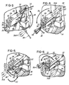
- Procédé pour connecter un segment de fil, ayant une extrémité fixe et une extrémité libre, sur une borne ayant une saillie en languette se projetant depuis l'une des ces faces et ayant un bord assurant une liaison de ladite première face, ledit procédé comprenant les étapes de :
mise en place d'une partie dudit segment de fil entre un coté de ladite languette et ladite première face de ladite borne;
bouclage dudit segment de fil autour de l'autre coté de ladite languette;
extension dudit segment de fil au delà de ladite languette et cintrage dudit segment de façon qu'une partie dudit segment se trouvant entre ladite languette et ladite extrémité libre dudit segment s'étendent sur ledit bord de ladite borne; et
traction sur ledit segment de fil, avec une force suffisante pour que ledit segment de fil soit étiré de manière à se rompre sur un angle dudit bord de ladite borne. - Procédé selon la revendication 1, comprenant en outre l'étape de saisie dudit segment de fil, à l'aide de moyens de saisie, pouvant être commandés pour appliquer différentes pressions de saisie sur ledit segment de fil, saisie initiales dudit segment de fil avec une pression suffisamment faible de manière que ledit segment de fil puisse être tiré par ledit moyen de saisie lorsque ledit segment de fil est bouclé autour de ladite languette et plié autour dudit bord, et augmentation de la pression de saisie appliquée audit segment de fil par ledit moyen de saisie, après que ledit segment de fil ait été plié sur ledit bord et avant ladite étape de traction, de manière que ledit segment de fil soit saisi avec une pression suffisante pour que ledit segment de fil ne soit pas tiré dans ledit moyen de saisie une fois que ledit segment de fil a été rompu.
- Le procédé selon la revendication 1, dans lequel le segment de fil est un conducteur à bobine de fil s'étendant depuis un bobine de stator enroulé sur un noyau de stator ayant une extrémité libre maintenue de façon relativement lâche par un collier à fil.
- Procédé selon la revendication 3, comprenant en outre l'étape de saisie dudit conducteur de bobine, à l'aide de moyen de saisie pouvant être commandé pour appliquer différentes pressions de saisie audit conducteur de bobine, pour initialement saisir ledit conducteur de bobine avec une pression suffisamment faible, de manière que ledit conducteur de bobine puisse être étiré à travers ledit moyen de saisie lorsque ledit conducteur de bobine est bouclé autour de ladite languette et plié autour, et à augmenter la pression de saisie appliquée audit conducteur de bobine par ledit moyen de saisie après que ledit conducteur de bobine a été plié sur ledit bord et avant ladite étape de traction de manière que ledit conducteur de bobine soit saisie avec une pression suffisante pour que ce dit conducteur de bobine ne soit pas tiré à travers ledit moyen de saisie une fois que ledit conducteur de bobine est rompu.
- Procédé selon la revendication 3, dans lequel le noyau de stator est un noyau de stator de moteur électrique comprenant une pièce polaire autour de laquelle le bobine de stator est enroulé, ladite borne étant montée dans, et faisant saillie depuis, un support de borne monté sur le noyau, et ladite borne comprenant un organe en feuille ayant des première et deuxième faces sensiblement parallèles et une paire de bords, reliant auxdites faces, pour constituer entre eux des angles, ladite languette se projetant depuis ladite première face, et dans lequel le procédé comprenant les étapes de :
saisie dudit conducteur de bobine à l'aide de moyen de saisie à pression commandable, en un point situé entre la borne sur laquelle ledit conducteur de bobine doit être relié et ladite extrémité libre, et plus près de ladite borne que ladite extrémité libre, avec une pression suffisamment faible pour que ledit conducteur de bobine puisse être tiré à travers ledit moyen de saisie;
déplacement dudit moyen de saisie, de la distance nécessaire pour recouvrir la partie dudit conducteur de bobine se trouvant entre l'une des faces de ladite languette, et ladite première face de ladite borne, pour ensuite boucler ledit conducteur de bobine pour de l'autre face de ladite languette, pour étendre ledit conducteur de bobine une fois passer ladite languette sur ladite première face, pour boucler ledit conducteur de bobine sur l'une desdits bords, et pour étendre ledit conducteur de bobine sur ladite deuxième face de ladite borne;
augmentation de la pression de saisie appliquée audit conducteur de bobine par ledit moyen de saisie; et
traction dudit conducteur de bobine à l'aide des moyens de saisie, avec une force suffisante pour qu'il soit étiré et rompu sur l'angle de ladite borne, entre ledit dernier bord mentionné et ladite deuxième face de ladite borne.
Applications Claiming Priority (2)
| Application Number | Priority Date | Filing Date | Title |
|---|---|---|---|
| US412316 | 1989-09-25 | ||
| US07/412,316 US4951379A (en) | 1989-09-25 | 1989-09-25 | Method for connecting wires to terminals having tangs and cutting the wires at the terminals |
Publications (2)
| Publication Number | Publication Date |
|---|---|
| EP0425069A1 EP0425069A1 (fr) | 1991-05-02 |
| EP0425069B1 true EP0425069B1 (fr) | 1995-01-18 |
Family
ID=23632508
Family Applications (1)
| Application Number | Title | Priority Date | Filing Date |
|---|---|---|---|
| EP90304695A Expired - Lifetime EP0425069B1 (fr) | 1989-09-25 | 1990-04-30 | Procédé pour connecter des fils aux serre-câbles ayant des languettes et pour découper ces fils |
Country Status (4)
| Country | Link |
|---|---|
| US (1) | US4951379A (fr) |
| EP (1) | EP0425069B1 (fr) |
| JP (1) | JPH03118748A (fr) |
| DE (1) | DE69016155T2 (fr) |
Families Citing this family (27)
| Publication number | Priority date | Publication date | Assignee | Title |
|---|---|---|---|---|
| US5077174A (en) * | 1990-04-10 | 1991-12-31 | E. I. Du Pont De Nemours And Company | Positive working dry film element having a layer of resist composition |
| US5145764A (en) * | 1990-04-10 | 1992-09-08 | E. I. Du Pont De Nemours And Company | Positive working resist compositions process of exposing, stripping developing |
| US5214838A (en) * | 1990-04-20 | 1993-06-01 | Globe Products Inc. | Method for inserting stator coil lead wires into terminals having wire-receiving channels |
| DE69107658T3 (de) * | 1990-04-20 | 2001-10-11 | Globe Products Inc | Verfahren und Gerät zur Einführung von Statorwicklungsadern in Drahtaufnahmekanäle aufweisende Verbinder. |
| US5090107A (en) * | 1990-04-20 | 1992-02-25 | Globe Products Inc. | Apparatus for inserting stator coil lead wires into terminals having wire-receiving channels |
| US5233751A (en) * | 1990-05-25 | 1993-08-10 | Axis U.S.A., Inc. | Method and apparatus for connecting intermediate stator coil leads |
| US5065503A (en) * | 1990-08-01 | 1991-11-19 | Axis, U.S.A., Inc. | Apparatus for connecting stator coil leads |
| US5186405A (en) * | 1990-09-27 | 1993-02-16 | Globe Products Inc. | Programmable lead pull method and apparatus for use with a stator winding machine |
| EP0751607A3 (fr) * | 1990-09-25 | 1997-08-27 | Globe Products Inc | Procédé et appareil de fabrication d'enroulements statoriques |
| US5370324A (en) * | 1990-09-25 | 1994-12-06 | Globe Products Inc. | Stator winding method and apparatus |
| US5090108A (en) * | 1990-10-17 | 1992-02-25 | Globe Products Inc. | Stator coil winding and lead termination method and apparatus |
| US5193755A (en) * | 1990-12-12 | 1993-03-16 | Axis Usa, Inc. | Two-wire stator winding machine |
| US5413403A (en) * | 1993-08-09 | 1995-05-09 | Globe Products Inc. | Lead pull assembly |
| US5535503A (en) * | 1993-12-03 | 1996-07-16 | Globe Products Inc. | Stator lead wire connection method and apparatus |
| US5495659A (en) * | 1994-03-30 | 1996-03-05 | Globe Products Inc. | Stator manufacturing apparatus |
| US5685061A (en) * | 1995-04-20 | 1997-11-11 | Globe Products Inc. | Stator manufacturing method |
| US5755021A (en) * | 1995-07-07 | 1998-05-26 | Globe Products Inc. | Stator lead wire connecting method |
| US5855058A (en) * | 1996-04-18 | 1999-01-05 | Globe Products Inc. | Armature manufacturing apparatus |
| WO1998001934A1 (fr) * | 1996-07-09 | 1998-01-15 | Globe Products Inc. | Procede et appareil de connexion d'un fil de raccordement |
| US5950300A (en) * | 1996-10-28 | 1999-09-14 | Globe Products Inc. | Stator coil lead termination method and apparatus |
| WO1998039835A1 (fr) * | 1997-02-24 | 1998-09-11 | Globe Products Inc. | Procede et appareil servant a la fabrication de stators |
| JP3374776B2 (ja) * | 1999-02-05 | 2003-02-10 | 株式会社デンソー | 車両用交流発電機 |
| JP3201397B2 (ja) * | 1999-03-30 | 2001-08-20 | 株式会社デンソー | 回転電機の製造方法 |
| US6523773B2 (en) * | 2000-03-29 | 2003-02-25 | Axis Usa, Inc. | Wire sensors for tang termination in dynamo-electric machine manufacturing systems |
| EP2258303B1 (fr) * | 2000-04-19 | 2013-09-18 | OraMetrix, Inc. | Système pour créer un modèle individuel virtuel tridimensionnel d'une dent |
| CN102545413B (zh) * | 2006-11-20 | 2014-07-09 | 阿斯莫株式会社 | 电枢和电机 |
| DE102018100016A1 (de) * | 2018-01-02 | 2019-07-04 | Elmotec Statomat Holding GmbH | Verfahren und Vorrichtung zur Herstellung von Rotoren und Statoren einschließlich der Konfektionierung von Anschlussdrähten |
Family Cites Families (9)
| Publication number | Priority date | Publication date | Assignee | Title |
|---|---|---|---|---|
| US3713208A (en) * | 1971-09-03 | 1973-01-30 | Globe Tool Eng Co | Armature winding method |
| US3812577A (en) * | 1973-03-13 | 1974-05-28 | Globe Tool Eng Co | Armature winding method and apparatus |
| US3984908A (en) * | 1975-10-01 | 1976-10-12 | Amp Incorporated | Stator terminal assembly machine |
| CH622913A5 (fr) * | 1978-02-07 | 1981-04-30 | Micafil Ag | |
| CH652538A5 (de) * | 1981-01-29 | 1985-11-15 | Micafil Ag | Vorrichtung zum verbinden der wicklungsenden mit den anschlussklemmen von statoren elektrischer maschinen und ein verfahren zum betrieb derselben. |
| US4631882A (en) * | 1985-02-26 | 1986-12-30 | Sease R Gregg | Molding strips and assembly thereof for mounting a flexible covering onto a support surface |
| US4633577A (en) * | 1984-10-19 | 1987-01-06 | The Globe Tool & Engineering Company | Armature winding method and apparatus |
| US4692974A (en) * | 1985-06-04 | 1987-09-15 | The Boeing Company | Connector block for use with a robotic wire harness assembly system |
| US4827601A (en) * | 1987-10-13 | 1989-05-09 | Statomat-Globe, Inc. | Armature winding method and apparatus |
-
1989
- 1989-09-25 US US07/412,316 patent/US4951379A/en not_active Expired - Fee Related
-
1990
- 1990-04-30 EP EP90304695A patent/EP0425069B1/fr not_active Expired - Lifetime
- 1990-04-30 DE DE69016155T patent/DE69016155T2/de not_active Expired - Fee Related
- 1990-09-25 JP JP2258794A patent/JPH03118748A/ja active Pending
Also Published As
| Publication number | Publication date |
|---|---|
| DE69016155D1 (de) | 1995-03-02 |
| EP0425069A1 (fr) | 1991-05-02 |
| US4951379A (en) | 1990-08-28 |
| DE69016155T2 (de) | 1995-08-10 |
| JPH03118748A (ja) | 1991-05-21 |
Similar Documents
| Publication | Publication Date | Title |
|---|---|---|
| EP0425069B1 (fr) | Procédé pour connecter des fils aux serre-câbles ayant des languettes et pour découper ces fils | |
| US5090108A (en) | Stator coil winding and lead termination method and apparatus | |
| US5370324A (en) | Stator winding method and apparatus | |
| US5090107A (en) | Apparatus for inserting stator coil lead wires into terminals having wire-receiving channels | |
| US5742997A (en) | Stator manufacturing method | |
| US3713208A (en) | Armature winding method | |
| EP0478302B1 (fr) | Procédé et appareil de fabrication d'enroulements statoriques | |
| JPH06343240A (ja) | 固定子コイルのリード接続方法および装置 | |
| EP0490173B1 (fr) | Machine à bobiner les stators | |
| CN110625624B (zh) | 线头扎紧仿真机器人及其使用方法 | |
| US5586384A (en) | Stator manufacturing method and apparatus | |
| US5755021A (en) | Stator lead wire connecting method | |
| US5765274A (en) | Stator manufacturing method | |
| US5685061A (en) | Stator manufacturing method | |
| EP0453311B1 (fr) | Méthode et appareil d'insertion des extrémités des fils de bobinage d'un stator dans des connecteurs ayant des cannaux de réception de conducteurs | |
| CN212648706U (zh) | 一种拨开干涉线的机构 | |
| US5784771A (en) | Stator manufacturing method and apparatus | |
| CN212648704U (zh) | 一种线束夹裁机构 | |
| EP1309072A2 (fr) | Procédé et dispositif pour la terminaison des fils de bobines de machines dynamoélectriques | |
| JP5991275B2 (ja) | 巻線部品の結線方法および結線装置 | |
| US5651177A (en) | Stator manufacturing and testing method and apparatus | |
| CA2183879A1 (fr) | Fabrication d'un stator, procede et dispositif d'essai | |
| JP3048098B2 (ja) | 電線付端子の挿入方法および挿入装置 | |
| JPH0555994B2 (fr) | ||
| KR970002010B1 (ko) | 발전기의 고정자코일과 정류자의 자동결선방법 |
Legal Events
| Date | Code | Title | Description |
|---|---|---|---|
| PUAI | Public reference made under article 153(3) epc to a published international application that has entered the european phase |
Free format text: ORIGINAL CODE: 0009012 |
|
| AK | Designated contracting states |
Kind code of ref document: A1 Designated state(s): CH DE FR GB IT LI |
|
| 17P | Request for examination filed |
Effective date: 19910603 |
|
| 17Q | First examination report despatched |
Effective date: 19931008 |
|
| GRAA | (expected) grant |
Free format text: ORIGINAL CODE: 0009210 |
|
| AK | Designated contracting states |
Kind code of ref document: B1 Designated state(s): CH DE FR GB IT LI |
|
| ITF | It: translation for a ep patent filed |
Owner name: JACOBACCI & PERANI S.P.A. |
|
| REF | Corresponds to: |
Ref document number: 69016155 Country of ref document: DE Date of ref document: 19950302 |
|
| ET | Fr: translation filed | ||
| PLBE | No opposition filed within time limit |
Free format text: ORIGINAL CODE: 0009261 |
|
| STAA | Information on the status of an ep patent application or granted ep patent |
Free format text: STATUS: NO OPPOSITION FILED WITHIN TIME LIMIT |
|
| 26N | No opposition filed | ||
| PGFP | Annual fee paid to national office [announced via postgrant information from national office to epo] |
Ref country code: FR Payment date: 19960410 Year of fee payment: 7 |
|
| PGFP | Annual fee paid to national office [announced via postgrant information from national office to epo] |
Ref country code: GB Payment date: 19960422 Year of fee payment: 7 |
|
| PGFP | Annual fee paid to national office [announced via postgrant information from national office to epo] |
Ref country code: DE Payment date: 19960429 Year of fee payment: 7 |
|
| PGFP | Annual fee paid to national office [announced via postgrant information from national office to epo] |
Ref country code: CH Payment date: 19960508 Year of fee payment: 7 |
|
| PG25 | Lapsed in a contracting state [announced via postgrant information from national office to epo] |
Ref country code: LI Free format text: LAPSE BECAUSE OF NON-PAYMENT OF DUE FEES Effective date: 19970430 Ref country code: GB Effective date: 19970430 Ref country code: CH Free format text: LAPSE BECAUSE OF NON-PAYMENT OF DUE FEES Effective date: 19970430 |
|
| REG | Reference to a national code |
Ref country code: CH Ref legal event code: PL |
|
| GBPC | Gb: european patent ceased through non-payment of renewal fee |
Effective date: 19970430 |
|
| PG25 | Lapsed in a contracting state [announced via postgrant information from national office to epo] |
Ref country code: FR Free format text: LAPSE BECAUSE OF NON-PAYMENT OF DUE FEES Effective date: 19971231 |
|
| PG25 | Lapsed in a contracting state [announced via postgrant information from national office to epo] |
Ref country code: DE Free format text: LAPSE BECAUSE OF NON-PAYMENT OF DUE FEES Effective date: 19980101 |
|
| REG | Reference to a national code |
Ref country code: FR Ref legal event code: ST |
|
| PG25 | Lapsed in a contracting state [announced via postgrant information from national office to epo] |
Ref country code: IT Free format text: LAPSE BECAUSE OF NON-PAYMENT OF DUE FEES Effective date: 20050430 |