EP0425069B1 - Method for connecting wires to terminals having tangs and cutting the wires at the terminals - Google Patents
Method for connecting wires to terminals having tangs and cutting the wires at the terminals Download PDFInfo
- Publication number
- EP0425069B1 EP0425069B1 EP90304695A EP90304695A EP0425069B1 EP 0425069 B1 EP0425069 B1 EP 0425069B1 EP 90304695 A EP90304695 A EP 90304695A EP 90304695 A EP90304695 A EP 90304695A EP 0425069 B1 EP0425069 B1 EP 0425069B1
- Authority
- EP
- European Patent Office
- Prior art keywords
- coil lead
- terminal
- wire segment
- wire
- tang
- Prior art date
- Legal status (The legal status is an assumption and is not a legal conclusion. Google has not performed a legal analysis and makes no representation as to the accuracy of the status listed.)
- Expired - Lifetime
Links
Images


Classifications
-
- H—ELECTRICITY
- H02—GENERATION; CONVERSION OR DISTRIBUTION OF ELECTRIC POWER
- H02K—DYNAMO-ELECTRIC MACHINES
- H02K15/00—Methods or apparatus specially adapted for manufacturing, assembling, maintaining or repairing of dynamo-electric machines
- H02K15/08—Forming windings by laying conductors into or around core parts
- H02K15/095—Forming windings by laying conductors into or around core parts by laying conductors around salient poles
-
- H—ELECTRICITY
- H01—ELECTRIC ELEMENTS
- H01R—ELECTRICALLY-CONDUCTIVE CONNECTIONS; STRUCTURAL ASSOCIATIONS OF A PLURALITY OF MUTUALLY-INSULATED ELECTRICAL CONNECTING ELEMENTS; COUPLING DEVICES; CURRENT COLLECTORS
- H01R43/00—Apparatus or processes specially adapted for manufacturing, assembling, maintaining, or repairing of line connectors or current collectors or for joining electric conductors
-
- H—ELECTRICITY
- H02—GENERATION; CONVERSION OR DISTRIBUTION OF ELECTRIC POWER
- H02K—DYNAMO-ELECTRIC MACHINES
- H02K15/00—Methods or apparatus specially adapted for manufacturing, assembling, maintaining or repairing of dynamo-electric machines
- H02K15/0056—Manufacturing winding connections
-
- H—ELECTRICITY
- H02—GENERATION; CONVERSION OR DISTRIBUTION OF ELECTRIC POWER
- H02K—DYNAMO-ELECTRIC MACHINES
- H02K15/00—Methods or apparatus specially adapted for manufacturing, assembling, maintaining or repairing of dynamo-electric machines
- H02K15/0056—Manufacturing winding connections
- H02K15/0068—Connecting winding sections; Forming leads; Connecting leads to terminals
-
- H—ELECTRICITY
- H02—GENERATION; CONVERSION OR DISTRIBUTION OF ELECTRIC POWER
- H02K—DYNAMO-ELECTRIC MACHINES
- H02K3/00—Details of windings
- H02K3/46—Fastening of windings on the stator or rotor structure
- H02K3/52—Fastening salient pole windings or connections thereto
- H02K3/521—Fastening salient pole windings or connections thereto applicable to stators only
- H02K3/522—Fastening salient pole windings or connections thereto applicable to stators only for generally annular cores with salient poles
-
- Y—GENERAL TAGGING OF NEW TECHNOLOGICAL DEVELOPMENTS; GENERAL TAGGING OF CROSS-SECTIONAL TECHNOLOGIES SPANNING OVER SEVERAL SECTIONS OF THE IPC; TECHNICAL SUBJECTS COVERED BY FORMER USPC CROSS-REFERENCE ART COLLECTIONS [XRACs] AND DIGESTS
- Y10—TECHNICAL SUBJECTS COVERED BY FORMER USPC
- Y10T—TECHNICAL SUBJECTS COVERED BY FORMER US CLASSIFICATION
- Y10T29/00—Metal working
- Y10T29/49—Method of mechanical manufacture
- Y10T29/49002—Electrical device making
- Y10T29/49009—Dynamoelectric machine
- Y10T29/49011—Commutator or slip ring assembly
-
- Y—GENERAL TAGGING OF NEW TECHNOLOGICAL DEVELOPMENTS; GENERAL TAGGING OF CROSS-SECTIONAL TECHNOLOGIES SPANNING OVER SEVERAL SECTIONS OF THE IPC; TECHNICAL SUBJECTS COVERED BY FORMER USPC CROSS-REFERENCE ART COLLECTIONS [XRACs] AND DIGESTS
- Y10—TECHNICAL SUBJECTS COVERED BY FORMER USPC
- Y10T—TECHNICAL SUBJECTS COVERED BY FORMER US CLASSIFICATION
- Y10T29/00—Metal working
- Y10T29/49—Method of mechanical manufacture
- Y10T29/49002—Electrical device making
- Y10T29/49009—Dynamoelectric machine
- Y10T29/49012—Rotor
Landscapes
- Engineering & Computer Science (AREA)
- Manufacturing & Machinery (AREA)
- Power Engineering (AREA)
- Manufacture Of Motors, Generators (AREA)
- Insulation, Fastening Of Motor, Generator Windings (AREA)
Description
- This invention relates to a method for connecting wires to terminals having tangs and cutting the wires at the terminals and to products produced by the method. The invention is primarily directed to a method for connecting wire coil leads of electric motor stators but may be used with numerous other products having such terminals.
- Two pole stators for universal electric motors typically have a pair of coils comprising magnet wire having an insulating coating wound around pole pieces formed on a laminated core. Each coil has two or more wire leads extending therefrom. A practice that has become commonplace in recent years is to mount terminals having lead-clamping hooks or tangs on the stator cores adjacent the coils to which the coil leads are connected. Such a terminal often is in the form of a flat plate or a U-shaped clip and has a wire-clamping tang struck outwardly from one of its faces.
- In preparation for connection of coil leads to terminals having lead-clamping tangs, each of the coil leads may be cut at the end of the coil winding process with a sufficient length that it can be held by a stationary wire clamp in a position wherein it extends across the face of the stator and past its associated terminal so that it may be mechanically manipulated to be connected to the terminal. In order to achieve connection of a coil lead to a terminal, the practice has been to advance a movable wire gripper toward the coil lead, manipulate the movable gripper to lay the wire lead in the trough formed between the wire-clamping tang and the adjacent face of the terminal, peen the tang over the wire lead so that the lead is clamped between the tang and the adjacent face of the terminal, cut the wire lead adjacent the terminal, and retract and open the wire gripper to dispose of the excess wire. In a later step, usually accomplished at a different processing station, the coil leads are fused to the terminals by a welder. The heat of fusion melts the insulating coatings from the wires so that adequate electrical connections between the coil leads and the terminals are obtained.
- Portions of the foregoing manufacturing processes can be done manually but the more common practice is to use automatic machines. The wire handling, tang peening, and wire-cutting mechanisms of such machines are somewhat complex and the machines are usually tooled so that each machine is dedicated to the manufacture of but one stator configuration. If it is desired to use the machine for manufacturing a differently configured stator, the machine must be practically completely rebuilt.
- In US-A-4041604 there is disclosed a method of connecting stator coil lead wires to terminals, but the terminals do not have tangs and are provided with slots in their inner end portions to receive the lead wires. In connecting a lead wire to a terminal the lead wire is laid across the open end of a socket formed in a terminal support and the terminal is pushed into the socket so that the lead wire enters the slot of the terminal. A cutter severs the free end of the lead wire as the terminal approaches. This method is not possible for terminals with tangs.
- An object of this invention is to provide an improved method for connecting wire segments, especially wire coil leads of stator coils, to terminals having tangs.
- In accordance with the invention there is provided a method for connecting a wire segment having a fixed end and a free end to a terminal having a tang projecting from one face thereof and having an edge bounding said one face, said method comprising the steps of:
laying a portion of said wire segment between one side of said tang and said one face of said terminal;
looping said wire segment around the other side of said tang;
extending said wire segment past said tang and bending said segment so that a portion of said segment between said tang and said free end of said segment is extended over said edge of said terminal; and
pulling said wire segment with sufficient force that said wire segment is so stretched that it breaks at a corner of said edge of said terminal. - By the method of this invention it is possible to connect a wire segment, such as a stator coil lead, to a terminal having a tang with sufficient security that no additional means or method, such as a peening operation, is required to hold the wire segment on the terminal during subsequent processing until the wire segment is fused to the terminal. The method of the invention also means that it is possible to dispense with the need in an automatic terminal connecting machine to provide cutting means to cut a wire segment connected to a terminal.
- Carrying out the method of the invention preferably includes the step of gripping the wire segment between the fixed end and the free end sufficiently near its fixed end that the stretch of wire between its fixed end and its gripped portion can be controllably manipulated. (If this stretch of wire is too long, it may be too flexible or rubbery to enable it to be satisfactorily handled during the terminal connection and wire cutting process.) The wire segment may comprise a stator coil lead in which case its fixed end is at the stator coil and, in a common practice, its free end is releasably held by a clamp device stationarily mounted with respect to the stator coil.
- The wire segment can be gripped by gripper means of an industrial robot which gripper means is controllable to apply different gripping pressures to the wire segment.
- The wire segment is initially gripped with a pressure sufficiently low that it can slide along the gripper means as it is being manipulated to connect it to the terminal. The gripping pressure is increased prior to the pulling step so that sufficient pressure is applied that the free end of the wire segment is held clamped and will not be drawn through the gripper means when the wire is being stretched and severed.
- To perform the method of the invention the industrial robot need not be equipped with dedicated tooling specific to a particular product or device, such as a uniquely configured stator for electric motors. Accordingly, one industrial robot may be programmed so that it can make terminal connections and sever the terminal wires for many different stators or other devices. During intervals when the robot is not carrying out the method of this invention, it may also be used for other purposes, such as, for example, unloading stator cores or other devices.
- To retain optimum control of the stretch of wire between its gripped portion and its fixed end, the movements of the gripper means is in directions such that, if possible, the wire segment would be pulled from its fixed end. Since the wire segment cannot be pulled from its fixed end, the gripper means slides along the wire segment toward the free end the wire segment as portions of the wire segment accumulate on the terminal. Accordingly, the stretch of the wire segment between its fixed end and its clamped portion remain taut throughout the wire connection and severing process.
- Other objects and advantages will become apparent from the following description and the drawings.
- FIG. 1 is a simplified and fragmentary perspective view of a wound stator with coil leads extending from the coils wound thereon, a support for the stator, stationary wire clamps for holding the coil leads, and a portion of a robot for connecting the coil leads to terminals on the stator core in accordance with this invention. The parts are shown positioned in FIG. 1 preliminary to connecting the leads to the terminals.
- FIG. 2 is an enlarged, fragmentary perspective view of a portion of the stator of FIG. 1 and a portion of the robot and illustrates a first step in the method of connecting a coil lead to a terminal and severing the coil lead in accordance with this invention.
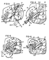
- FIGS. 3 through 8 are enlarged, fragmentary perspective views similar to FIG. 2 and illustrate in succession the steps for completing the connection of the coil lead to the terminal and the severing of the coil lead.
- FIG. 9 is an end elevational view of the portion of the terminal to which the wire lead is connected in accordance with this invention and the coil lead connected thereto.
- FIG. 10 is a fragmentary perspective view of a stator having a terminal configuration that differs from the terminal of the stator illustrated in FIGS. 1 through 9 and to which a coil lead has been connected in accordance with the method of this invention.
- FIG. 1 fragmentarily illustrates one stage of a multi-stage production line for producing stators for electric motors. The structure fragmentarily illustrated comprises a
stator support assembly 10 that supports and clamps astator 12 of the type comprising a laminatedstator core 14 having pole pieces 16 about which a pair ofstator field coils stator 12 is only partially completed and lacks terminal connections by which electrical energy would be supplied to the field coils. - During the terminal connecting and coil lead cutting process described below, the
stator support assembly 10 is stationary. Those familiar with the art will recognize that thestator support assembly 10 may form part of a turret or other workpiece handling machinery by which the support assembly is moved into a station at which the method of this invention is practiced and thereafter moved out of the station so that the method can be repeatedly carried out on successive stators. - As will be understood by those familiar with the art, a number of operations leading toward completion of the
stator 12 have already been performed. In a preceding manufacturing step, a pair ofterminal boards stator core 14 in face-contacting relation to the end face of thestator core 14. It will be noted that theterminal boards terminal boards upstanding sockets 26, one of which is shown enlarged in FIGS. 2 through 8, projecting therefrom. Thesockets 26 project outwardly from theterminal boards stator core 14. - Prior to the time the
coils metal terminals 28 are inserted into thesockets 26. Theterminals 28 are constructed to interfit with mating connectors in the final assembly of the motor of which thestator 12 is a part. Terminals such as this may have various different configurations. Theparticular terminal 28 illustrated in FIGS. 1 through 9 comprises a U-shaped spring clip having afirst leg 30 lodged within thesocket 26 and asecond leg 32 that projects out of thesocket 26. Aterminal tang 34, which may be struck out of thesecond terminal leg 32, projects from the outer face, designated 36, thereof. - Also in a prior production stage, after the
coils field coils suitable clamp assemblies 46 fixedly mounted on thestator support assembly 10. The depiction of the clamp assemblies 46 in FIG. 1 is somewhat simplified since they do not form part of this invention. They exert clamping pressures on the coil leads sufficient to retain them oriented as shown in FIG. 1 until the leads are pulled from the clamps. The clamps may be spring powered or may be powered by air actuators or other suitable means. Also in a prior operating stage, the free ends of the coil leads 38, 40, 42, and 44 are cut to the desired length so that their free ends project beyond theclamps 46. - As a result of the prior operations mentioned above, each of the coil leads 38, 40, 42, and 44 is extended from its
stator coil stator core 14, past itsrespective terminal 28, and through its respectivestationary clamp 46. The present invention is concerned with a method by which the coil leads 38, 40, 42, and 44 are connected to theterminals 28 after the parts have reached the position shown in FIG. 1 and the excess length thereof severed at theterminals 28. - In its broader aspects, the method of this invention may be carried out manually but it is particularly intended, for high speed production purposes, to be carried out by an industrial robot generally designated 50. The portion of the
robot 50 shown in the drawings includes anarm 52 and agripper member 54 having a pair ofgripper jaws 56. For reasons which will become apparent, thegripper jaws 56 are so controlled that the clamping pressures applied by them can be varied. For example, as will be readily recognized by those familiar in the art, thegripper jaws 56 may be controlled by a variable air actuator. Otherwise, therobot 50 may be entirely conventional and is not further illustrated herein. Although different types of robots may be-useful in the practice of this invention, a three-axis Cartesian robot, such as is available from Hirata Corporation of America, 3901 Industrial Blvd., Indianapolis, Indiana 46254, is presently preferred. - With reference to FIGS. 1 and 2, a secure connection of the
coil lead 38 to thesecond leg 32 of its associatedterminal 28 commences in accordance with this invention by the advancement of therobot arm 52 along anaxis 58 parallel to the axis, designated 60, of thestator 12 clamped to thestator support assembly 10. After the robot arm has moved, as indicated by thearrow 62 in FIG. 2, to a position wherein thegripper jaws 56 straddle thecoil lead 38, movement of thearm 52 is stopped and thejaws 56 are actuated to grip thecoil lead 38 as shown in FIG. 2. The gripped portion of thecoil lead 38 is between its associatedterminal support socket 26 and its free end but much closer to itsterminal socket 26 than to its free end so that the stretch of the coil lead between the coil from which it extends and thegripper jaws 56 is sufficiently short that it does not flex or buckle uncontrollably during the manipulations of thegripper jaws 56. - When the
coil lead 38 is first gripped by thegripper jaws 56, the clamping pressure of the grippingjaws 56 is sufficiently low that thegripper jaws 56 will slide along thecoil lead 38 as portions of thecoil lead 38 are extended over parts of theterminal leg 32. At a later stage, described below with reference to FIG. 8, the clamping pressure is increased so that the coil lead is firmly clamped when the wire lead is stretched and severed against theterminal leg 32. - The
stationary clamp assemblies 46 are preferably operable so that their grip on the coil leads can be released. If so, thestationary clamp assembly 46 associated with thecoil lead 38 is operated to release its grip thereon after thecoil lead 38 is gripped by thegripper jaws 56. Optionally, thestationary clamp assemblies 46 may clamp the coil leads with such a low clamping pressure that it would not be necessary to release the leads; the leads will simply be pulled from their respective clamps by subsequent processing steps. - With the
coil lead 38 held clamped by thegripper jaws 56, therobot arm 52 is manipulated through a continuous series of steps illustrated in FIGS. 3 through 7 to securely connect thecoil lead 38 to theterminal leg 32. The movements of thegripper jaws 56 are shown sequentially in each of FIGS. 3 through 7, with the starting position for each figure shown byphantom lines 56A and the ending position shown byfull lines 56. The starting position for each of FIGS. 3 through 7 is the same as the ending position of each of the preceding FIGS. 2 through 6, respectively. - In accordance with this invention, the
clamp jaws 56 are so manipulated, as indicated by thearrow 64 in FIG. 3, that thecoil lead 38, which was originally extended below the lower surface of itssocket 26, is bent upwardly around the lower,outer corner 66 of thesocket 26 and extended behind a wire-support protuberance 68 located on the outer side face of thesocket 26 as shown in FIG. 3. - The
coil lead 38 is then extended outwardly from the face of thestator core 14 along the length of theterminal support socket 26 by a movement of thegripper jaws 56 away from the stator core as indicated by thearrow 70 in FIG. 4. Many terminals do not have a wire-support protuberance such as theprotuberance 68 and the manipulation of thecoil lead 38 by thejaws 56, as thus far described, will be unneccessary with many terminals. - FIG. 5 illustrates a key step in the practice of the method in accordance with this invention by which the
gripper jaws 56 are moved, as indicated by thearrow 72, vertically downwardly and then horizontally toward thestator core 14 to first lay thecoil lead 38 in the trough, designated 74, formed between thetang 34 and thefirst face 36 of theterminal leg 32 and to then pull thecoil lead 38 toward thestator core 14. In consequence, the segment of thecoil lead 38 coursed over thetang 34 exerts a pulling force on the terminal 28 tending to keep it seated within itssocket 26. - Here it should be noted that the length of the unsupported stretch of the
coil lead 38 between the thegripper jaws 56 and parts of the terminal 28 and itssocket 26 which are engaged by thecoil lead 38 remains substantially constant throughout the lead connection process. This is because thegripper jaws 56 slide along thecoil lead 38 toward its free end as needed to accommodate the lengths of thecoil lead 38 coursed over the terminal 28 and itssocket 26. This stretch of wire also stays relatively taut because all of the movements of the gripper jaws are in a direction tending to pull thecoil lead 38 from its fixed end. Accordingly, such stretch of wire is relatively short and taut and, therefore, remains controllable throughout the process. - FIG. 6 illustrates another key step in the method of this invention by which the
gripper jaws 56 are first moved, as indicated by the arrow 76 in FIG. 6, in a generally circular, counterclockwise, direction to extend the portion of thecoil lead 38 exiting from thetrough 74 around the outer side of thetang 34, thereby hooking or looping thecoil lead 38 about anedge 78 of thetang 34 and around the stretch, designated 80, of thecoil lead 38 entering the lead-receivingtrough 74. Thecoil lead 38 is also thereby extended over the upper edge, designated 84 in FIGS. 7 through 9, of the secondterminal leg 32. - The
jaws 56 are then moved generally downwardly, as indicated by thearrow 82 in FIG. 7, whereupon thecoil lead 38 is extended downwardly along the backside of theterminal leg 32 and brought into engagement with theupper edge 84. By virtue of the preceding steps, thecoil lead 38 is looped around an edge of thetang 34, extended over itself, and also bent around theupper edge 84 of theterminal leg 32. - With reference to FIGS. 8 and 9, the free end of the
coil lead 38 is now severed from the portion thereof connected to theterminal leg 32 by the simple expedient of pulling downwardly on the free end of thecoil lead 38 with sufficient force that thecoil lead 38 is stretched over the toprear corner 86 of theterminal leg 32 to the point that it breaks at that corner. This step is accomplished by moving thejaws 56 downwardly as shown by thearrow 88 in FIG. 8 until thecoil lead 38 breaks against theterminal leg corner 86, leaving a severedwire remnant 90 in thejaws 56. Prior to the downward, wire-severing movement of thejaws 56, their clamping pressure is increased so that they firmly clamp the free end of thecoil lead 38 and will not slide off thecoil lead 38 as the lead is being stretched and broken. It may be noted in FIG. 9, which shows the final connection of thecoil lead 38 to theterminal leg 32, that the severed end of thelead 38 has a somewhat reduced diameter because of the stretching of the lead that occurs prior to breakage. Thecoil lead 38 is now tightly wrapped around theterminal tang 34 in a configuration resembling the Greek letter alpha. - During the wire-breaking movement of the
gripper jaws 56 illustrated in FIG. 8, the jaws should be so oriented that the stretch of thecoil lead 38 between thejaws 56 and theterminal corner 86 engages over only smoothly curved surfaces of thegripper jaws 56 to insure that the coil lead does not break at a jaw surface rather than at theterminal corner 86. As an alternative, thegripper jaws 56 could be so oriented that such stretch of thecoil lead 38 extends vertically between the mutually confronting jaw surfaces that clamp the lead so that such stretch of the lead does not lie along an outside surface of either of thejaws 56. - After the connection and breaking of the
coil lead 38 as described above, thegripper jaws 56 may be spread apart to release thewire remnant 90 and then repositioned to sequentially connect and sever the coil leads 40, 42, and 44. The connection and severing of the coil leads 40, 42, and 44 to the other terminals will proceed using the method described above, except for differences in movements of thejaws 56 necessitated by the different locations of the coil leads relative to their respective terminals. Thus, for example, the first movement of thegripper jaws 56 after gripping thecoil lead 40 would be downwardly rather than upwardly as in the case of thecoil lead 38. - Fig. 10 shows a modified terminal arrangement wherein a coil lead 110 is connected to a plate-
like terminal 112 mounted in asocket 114 on astator core 116. Here the lead 110 is extended directly from its associatedcoil 118 around atang 120 struck from afirst face 122 of the terminal 112 and then to thetop corner 124 of thesecond face 126. The method of connecting the coil lead 110 and breaking it at thecorner 124 is the same as that described above, except that there is no protuberance, such as theprotuberance 68, on thesocket 114 about which the coil lead 110 must be coursed. Accordingly, the wire grippers are first manipulated to grip the coil lead 110 and then moved to lay the coil lead between thetang 120 and the firstterminal face 122. The remaining steps to connect and sever the wire lead 110 are the same as those described above with respect to thecoil lead 38 after it is laid into thetrough 74. - Tests have shown that coil leads connected and broken in accordance with this invention are connected to their terminals with sufficient reliability that the method of this invention may be used in the mass production of stators. Furthermore, the lead connections to the terminals are sufficiently secure that there is no need to peen the tang over the lead at the completion of the lead connection and breaking steps of this invention. Instead, the stator may undergo further processing prior to the fusion of the leads to the terminals without additional attention to the leads and terminals.
- Although the presently preferred embodiments of this invention have been described, it will be understood that within the purview of this invention various changes maybe made within the scope of the appended claims. For example, the lead wire could be coursed around the tang to form more than one loop thereabout before being broken off at either the top or the bottom edge of the terminal leg.
Claims (5)
- A method for connecting a wire segment having a fixed end and a free end to a terminal having a tang projecting from one face thereof, and having an edge bounding said one face, said method comprising the steps of:
laying a portion of said wire segment between one side of said tang and said one face of said terminal;
looping said wire segment around the other side of said tang;
extending said wire segment past said tang and bending said segment so that a portion of said segment between said tang and said free end of said segment is extended over said edge of said terminal; and
pulling said wire segment with sufficient force that said wire segment is so stretched that it breaks at a corner of said edge of said terminal. - The method of claim 1 further comprising the step of gripping said wire segment by gripper means which is controllable to apply different gripping pressures to said wire segment, initially gripping said wire segment with a pressure sufficiently low that said wire segment may be drawn through said gripper means as said wire segment is being looped around said tang and bent around said edge, and increasing the gripping pressure applied to said wire segment by said gripping means after said wire segment is bent over said edge and before said pulling step so that said wire segment is gripped with sufficient pressure that said wire segment will not be drawn through said gripping means when said wire segment is being broken.
- The method of claim 1, wherein the wire segment is a wire coil lead wire extending from a stator coil wound on a stator core and having a free end relatively loosely held by a wire clamp.
- The method of claim 3 further comprising the step of gripping said coil lead by gripper means which is controllable to apply different gripping pressure to said coil lead, initially gripping said coil lead with a pressure sufficiently low that said coil lead may be drawn through said gripper means as said coil lead is being looped around said tang and bent around said edge, and increasing the gripping pressure applied to said coil lead by said gripping means after said coil lead is bent over said edge and before said pulling step so that said coil lead is gripped with sufficient pressure that said coil lead will not be drawn through said gripping means when said coil lead is being broken.
- The method of claim 3, wherein the stator core is an electric motor stator core comprising a pole piece around which the stator coil is wound, said terminal is mounted in and projects from a terminal support mounted on the core, and said terminal comprises a sheet member having substantially parallel first and second faces, and a pair of edges joining to said faces to form corners therebetween, said tang projecting from said first face, and wherein the method includes the steps of:
gripping said coil lead by pressure-controllable gripper means at a point between the terminal to which the coil lead is to be connected and said free end, and nearer said terminal than said free end, with a pressure sufficiently low that said coil lead may be drawn through said gripper means;
moving said gripper means as needed to lay the portion of said coil lead between the one of side of said tang and said first face of said terminal, to thereafter loop said coil lead around the other side of said tang, to extend said coil lead past said tang over said first face, to loop said coil lead over one of said edges, and to extend said coil lead along said second face of said terminal;
increasing the gripping pressure applied to said coil lead by said gripper means; and
pulling said coil lead by means of the gripping means with force sufficient that it is stretched and broken at the corner of said terminal between said least mentioned edge and said second face of said terminal.
Applications Claiming Priority (2)
| Application Number | Priority Date | Filing Date | Title |
|---|---|---|---|
| US07/412,316 US4951379A (en) | 1989-09-25 | 1989-09-25 | Method for connecting wires to terminals having tangs and cutting the wires at the terminals |
| US412316 | 1989-09-25 |
Publications (2)
| Publication Number | Publication Date |
|---|---|
| EP0425069A1 EP0425069A1 (en) | 1991-05-02 |
| EP0425069B1 true EP0425069B1 (en) | 1995-01-18 |
Family
ID=23632508
Family Applications (1)
| Application Number | Title | Priority Date | Filing Date |
|---|---|---|---|
| EP90304695A Expired - Lifetime EP0425069B1 (en) | 1989-09-25 | 1990-04-30 | Method for connecting wires to terminals having tangs and cutting the wires at the terminals |
Country Status (4)
| Country | Link |
|---|---|
| US (1) | US4951379A (en) |
| EP (1) | EP0425069B1 (en) |
| JP (1) | JPH03118748A (en) |
| DE (1) | DE69016155T2 (en) |
Families Citing this family (27)
| Publication number | Priority date | Publication date | Assignee | Title |
|---|---|---|---|---|
| US5145764A (en) * | 1990-04-10 | 1992-09-08 | E. I. Du Pont De Nemours And Company | Positive working resist compositions process of exposing, stripping developing |
| US5077174A (en) * | 1990-04-10 | 1991-12-31 | E. I. Du Pont De Nemours And Company | Positive working dry film element having a layer of resist composition |
| EP0453311B2 (en) * | 1990-04-20 | 2001-06-13 | Globe Products Inc. | Method and apparatus for inserting stator coil lead wires into terminals having wire-receiving channels |
| US5090107A (en) * | 1990-04-20 | 1992-02-25 | Globe Products Inc. | Apparatus for inserting stator coil lead wires into terminals having wire-receiving channels |
| US5214838A (en) * | 1990-04-20 | 1993-06-01 | Globe Products Inc. | Method for inserting stator coil lead wires into terminals having wire-receiving channels |
| US5233751A (en) * | 1990-05-25 | 1993-08-10 | Axis U.S.A., Inc. | Method and apparatus for connecting intermediate stator coil leads |
| US5065503A (en) * | 1990-08-01 | 1991-11-19 | Axis, U.S.A., Inc. | Apparatus for connecting stator coil leads |
| US5186405A (en) * | 1990-09-27 | 1993-02-16 | Globe Products Inc. | Programmable lead pull method and apparatus for use with a stator winding machine |
| US5370324A (en) | 1990-09-25 | 1994-12-06 | Globe Products Inc. | Stator winding method and apparatus |
| EP0751607A3 (en) * | 1990-09-25 | 1997-08-27 | Globe Products Inc | Stator winding method and apparatus |
| US5090108A (en) * | 1990-10-17 | 1992-02-25 | Globe Products Inc. | Stator coil winding and lead termination method and apparatus |
| US5193755A (en) * | 1990-12-12 | 1993-03-16 | Axis Usa, Inc. | Two-wire stator winding machine |
| US5413403A (en) * | 1993-08-09 | 1995-05-09 | Globe Products Inc. | Lead pull assembly |
| US5535503A (en) * | 1993-12-03 | 1996-07-16 | Globe Products Inc. | Stator lead wire connection method and apparatus |
| US5495659A (en) * | 1994-03-30 | 1996-03-05 | Globe Products Inc. | Stator manufacturing apparatus |
| US5685061A (en) * | 1995-04-20 | 1997-11-11 | Globe Products Inc. | Stator manufacturing method |
| US5755021A (en) * | 1995-07-07 | 1998-05-26 | Globe Products Inc. | Stator lead wire connecting method |
| US5855058A (en) * | 1996-04-18 | 1999-01-05 | Globe Products Inc. | Armature manufacturing apparatus |
| WO1998001934A1 (en) * | 1996-07-09 | 1998-01-15 | Globe Products Inc. | Stator lead wire connecting method and apparatus |
| EP1012947A2 (en) * | 1996-10-28 | 2000-06-28 | Globe Products Inc. | Stator coil lead termination method and apparatus |
| US5946792A (en) * | 1997-02-24 | 1999-09-07 | Globe Products Inc. | Stator manufacturing method and apparatus |
| JP3374776B2 (en) * | 1999-02-05 | 2003-02-10 | 株式会社デンソー | AC generator for vehicles |
| JP3201397B2 (en) * | 1999-03-30 | 2001-08-20 | 株式会社デンソー | Method of manufacturing rotating electric machine |
| US6523773B2 (en) * | 2000-03-29 | 2003-02-25 | Axis Usa, Inc. | Wire sensors for tang termination in dynamo-electric machine manufacturing systems |
| EP1301140B2 (en) * | 2000-04-19 | 2017-07-05 | OraMetrix, Inc. | Bending machine for a medical device |
| CN102545413B (en) * | 2006-11-20 | 2014-07-09 | 阿斯莫株式会社 | Armature and motor |
| DE102018100016A1 (en) * | 2018-01-02 | 2019-07-04 | Elmotec Statomat Holding GmbH | Method and device for the production of rotors and stators, including the assembly of connecting wires |
Family Cites Families (9)
| Publication number | Priority date | Publication date | Assignee | Title |
|---|---|---|---|---|
| US3713208A (en) * | 1971-09-03 | 1973-01-30 | Globe Tool Eng Co | Armature winding method |
| US3812577A (en) * | 1973-03-13 | 1974-05-28 | Globe Tool Eng Co | Armature winding method and apparatus |
| US3984908A (en) * | 1975-10-01 | 1976-10-12 | Amp Incorporated | Stator terminal assembly machine |
| CH622913A5 (en) * | 1978-02-07 | 1981-04-30 | Micafil Ag | |
| CH652538A5 (en) * | 1981-01-29 | 1985-11-15 | Micafil Ag | DEVICE FOR CONNECTING THE WINDING ENDS TO THE TERMINALS OF STATORS OF ELECTRICAL MACHINES AND A METHOD FOR OPERATING THE SAME. |
| US4633577A (en) * | 1984-10-19 | 1987-01-06 | The Globe Tool & Engineering Company | Armature winding method and apparatus |
| US4593452A (en) * | 1985-02-26 | 1986-06-10 | Amp Incorporated | Robotic harness maker |
| US4692974A (en) * | 1985-06-04 | 1987-09-15 | The Boeing Company | Connector block for use with a robotic wire harness assembly system |
| US4827601A (en) * | 1987-10-13 | 1989-05-09 | Statomat-Globe, Inc. | Armature winding method and apparatus |
-
1989
- 1989-09-25 US US07/412,316 patent/US4951379A/en not_active Expired - Fee Related
-
1990
- 1990-04-30 DE DE69016155T patent/DE69016155T2/en not_active Expired - Fee Related
- 1990-04-30 EP EP90304695A patent/EP0425069B1/en not_active Expired - Lifetime
- 1990-09-25 JP JP2258794A patent/JPH03118748A/en active Pending
Also Published As
| Publication number | Publication date |
|---|---|
| DE69016155T2 (en) | 1995-08-10 |
| US4951379A (en) | 1990-08-28 |
| JPH03118748A (en) | 1991-05-21 |
| DE69016155D1 (en) | 1995-03-02 |
| EP0425069A1 (en) | 1991-05-02 |
Similar Documents
| Publication | Publication Date | Title |
|---|---|---|
| EP0425069B1 (en) | Method for connecting wires to terminals having tangs and cutting the wires at the terminals | |
| US5090108A (en) | Stator coil winding and lead termination method and apparatus | |
| US5214838A (en) | Method for inserting stator coil lead wires into terminals having wire-receiving channels | |
| US5560555A (en) | Stator winding method | |
| US5090107A (en) | Apparatus for inserting stator coil lead wires into terminals having wire-receiving channels | |
| US5742997A (en) | Stator manufacturing method | |
| US3713208A (en) | Armature winding method | |
| EP0478302B1 (en) | Stator winding method and apparatus | |
| EP0490173B1 (en) | Stator winding machine | |
| CN110625624B (en) | Wire end fastening simulation robot and using method thereof | |
| US5755021A (en) | Stator lead wire connecting method | |
| US5765274A (en) | Stator manufacturing method | |
| US5685061A (en) | Stator manufacturing method | |
| EP0453311B1 (en) | Method and apparatus for inserting stator coil lead wires into terminals having wire-receiving channels | |
| CN212648706U (en) | Mechanism for pulling out interference line | |
| US5784771A (en) | Stator manufacturing method and apparatus | |
| JPH09510599A (en) | Stator manufacturing and testing method and apparatus | |
| CN212648704U (en) | Wire harness clamping and cutting mechanism | |
| EP1309072A2 (en) | Method and apparatus for terminating coil leads of dynamo-electric machine | |
| US5651177A (en) | Stator manufacturing and testing method and apparatus | |
| JPH0555994B2 (en) | ||
| KR970002010B1 (en) | Automatic winding method of stator coil and brush of a generator | |
| JP5991275B2 (en) | Wiring component wiring method and wiring device | |
| JPS5849071A (en) | Interphase insulator shaping device | |
| WO1999035730A1 (en) | Stator winding and coil lead termination method and apparatus |
Legal Events
| Date | Code | Title | Description |
|---|---|---|---|
| PUAI | Public reference made under article 153(3) epc to a published international application that has entered the european phase |
Free format text: ORIGINAL CODE: 0009012 |
|
| AK | Designated contracting states |
Kind code of ref document: A1 Designated state(s): CH DE FR GB IT LI |
|
| 17P | Request for examination filed |
Effective date: 19910603 |
|
| 17Q | First examination report despatched |
Effective date: 19931008 |
|
| GRAA | (expected) grant |
Free format text: ORIGINAL CODE: 0009210 |
|
| AK | Designated contracting states |
Kind code of ref document: B1 Designated state(s): CH DE FR GB IT LI |
|
| ITF | It: translation for a ep patent filed |
Owner name: JACOBACCI & PERANI S.P.A. |
|
| REF | Corresponds to: |
Ref document number: 69016155 Country of ref document: DE Date of ref document: 19950302 |
|
| ET | Fr: translation filed | ||
| PLBE | No opposition filed within time limit |
Free format text: ORIGINAL CODE: 0009261 |
|
| STAA | Information on the status of an ep patent application or granted ep patent |
Free format text: STATUS: NO OPPOSITION FILED WITHIN TIME LIMIT |
|
| 26N | No opposition filed | ||
| PGFP | Annual fee paid to national office [announced via postgrant information from national office to epo] |
Ref country code: FR Payment date: 19960410 Year of fee payment: 7 |
|
| PGFP | Annual fee paid to national office [announced via postgrant information from national office to epo] |
Ref country code: GB Payment date: 19960422 Year of fee payment: 7 |
|
| PGFP | Annual fee paid to national office [announced via postgrant information from national office to epo] |
Ref country code: DE Payment date: 19960429 Year of fee payment: 7 |
|
| PGFP | Annual fee paid to national office [announced via postgrant information from national office to epo] |
Ref country code: CH Payment date: 19960508 Year of fee payment: 7 |
|
| PG25 | Lapsed in a contracting state [announced via postgrant information from national office to epo] |
Ref country code: LI Free format text: LAPSE BECAUSE OF NON-PAYMENT OF DUE FEES Effective date: 19970430 Ref country code: GB Effective date: 19970430 Ref country code: CH Free format text: LAPSE BECAUSE OF NON-PAYMENT OF DUE FEES Effective date: 19970430 |
|
| REG | Reference to a national code |
Ref country code: CH Ref legal event code: PL |
|
| GBPC | Gb: european patent ceased through non-payment of renewal fee |
Effective date: 19970430 |
|
| PG25 | Lapsed in a contracting state [announced via postgrant information from national office to epo] |
Ref country code: FR Free format text: LAPSE BECAUSE OF NON-PAYMENT OF DUE FEES Effective date: 19971231 |
|
| PG25 | Lapsed in a contracting state [announced via postgrant information from national office to epo] |
Ref country code: DE Free format text: LAPSE BECAUSE OF NON-PAYMENT OF DUE FEES Effective date: 19980101 |
|
| REG | Reference to a national code |
Ref country code: FR Ref legal event code: ST |
|
| PG25 | Lapsed in a contracting state [announced via postgrant information from national office to epo] |
Ref country code: IT Free format text: LAPSE BECAUSE OF NON-PAYMENT OF DUE FEES Effective date: 20050430 |