EP1309072A2 - Method and apparatus for terminating coil leads of dynamo-electric machine - Google Patents
Method and apparatus for terminating coil leads of dynamo-electric machine Download PDFInfo
- Publication number
- EP1309072A2 EP1309072A2 EP02024703A EP02024703A EP1309072A2 EP 1309072 A2 EP1309072 A2 EP 1309072A2 EP 02024703 A EP02024703 A EP 02024703A EP 02024703 A EP02024703 A EP 02024703A EP 1309072 A2 EP1309072 A2 EP 1309072A2
- Authority
- EP
- European Patent Office
- Prior art keywords
- wire
- shape
- stator
- leads
- dynamo
- Prior art date
- Legal status (The legal status is an assumption and is not a legal conclusion. Google has not performed a legal analysis and makes no representation as to the accuracy of the status listed.)
- Withdrawn
Links
Images

Classifications
-
- H—ELECTRICITY
- H02—GENERATION; CONVERSION OR DISTRIBUTION OF ELECTRIC POWER
- H02K—DYNAMO-ELECTRIC MACHINES
- H02K15/00—Methods or apparatus specially adapted for manufacturing, assembling, maintaining or repairing of dynamo-electric machines
- H02K15/0056—Manufacturing winding connections
-
- H—ELECTRICITY
- H02—GENERATION; CONVERSION OR DISTRIBUTION OF ELECTRIC POWER
- H02K—DYNAMO-ELECTRIC MACHINES
- H02K15/00—Methods or apparatus specially adapted for manufacturing, assembling, maintaining or repairing of dynamo-electric machines
- H02K15/0056—Manufacturing winding connections
- H02K15/0068—Connecting winding sections; Forming leads; Connecting leads to terminals
-
- H—ELECTRICITY
- H02—GENERATION; CONVERSION OR DISTRIBUTION OF ELECTRIC POWER
- H02K—DYNAMO-ELECTRIC MACHINES
- H02K15/00—Methods or apparatus specially adapted for manufacturing, assembling, maintaining or repairing of dynamo-electric machines
- H02K15/08—Forming windings by laying conductors into or around core parts
- H02K15/095—Forming windings by laying conductors into or around core parts by laying conductors around salient poles
-
- Y—GENERAL TAGGING OF NEW TECHNOLOGICAL DEVELOPMENTS; GENERAL TAGGING OF CROSS-SECTIONAL TECHNOLOGIES SPANNING OVER SEVERAL SECTIONS OF THE IPC; TECHNICAL SUBJECTS COVERED BY FORMER USPC CROSS-REFERENCE ART COLLECTIONS [XRACs] AND DIGESTS
- Y10—TECHNICAL SUBJECTS COVERED BY FORMER USPC
- Y10T—TECHNICAL SUBJECTS COVERED BY FORMER US CLASSIFICATION
- Y10T29/00—Metal working
- Y10T29/49—Method of mechanical manufacture
- Y10T29/49002—Electrical device making
- Y10T29/49009—Dynamoelectric machine
Definitions
- the present invention relates to improved solutions for processing dynamo-electric machine components (e.g., armatures or stators for electric motors, generators, or alternators) through wire coil winding steps.
- dynamo-electric machine components e.g., armatures or stators for electric motors, generators, or alternators
- Wire coils are an integral part of the dynamo-electric machine components such as armatures and stators.
- the wire coils are made of insulated wire wound on ferromagnetic poles.
- the ferromagnetic poles may be formed, for example, in the case of a stator, by adjacent longitudinal slots running along the inner surface of the stator core.
- the wound wire coil ends or leads are connected to terminal posts or boards on the component.
- electric voltage is applied to the terminal posts.
- electric current passes through these wire coils generating electro-mechanical torques which cause the dynamo-electric machine armature to rotate.
- Wire coil-winding specifications (such as wire size, pitch, number of turns, and winding (pole) configuration) determine the operational rotational characteristics of the dynamo-electric machine.
- the dynamo-electric machine component wire coils are often wound using automated coil winding machinery that includes a wire dispenser or needle mounted on a moving arm, which dispenses wire drawn from a wire spool.
- Exemplary winders are described, for example, in commonly-assigned Santandrea et al. U.S. Patent 4,969,606, Santandrea et al. U.S. Patent 5,149,000, Santandrea et al. U.S. Patent 5,137,221, Santandrea et al. U.S. Patent 5,288,088 and, Stratico et al., U.S. Patent 5,257,745, and Stratico et al. U.S.
- the automated machinery may be used to have the wire dispenser travel back and forth through the stator bore alongside a pole, dispensing wire stretches that are deposited on the pole sides and ends to form the stator coil to design specifications.
- wire leads from the starting and ending wire stretches of the stator wire coil may be cut to suitable lengths and terminated.
- the terminated wire leads are then routed along safe paths, which do not mechanically or electrically interfere with machine operation, and fastened or attached to terminal posts on the stator.
- the cut wire leads may be held in temporary positions secured by wire grippers while the stator core is being processed in the winding machinery.
- the wire termination and final routing and terminal attachment procedures are often carried out either manually or using automated wire termination and connection machines after the stator core has been moved out from the winding machinery.
- inventive methods and apparatus for the termination of dynamo-electric machine component wire coil lead portions are provided.
- the inventive methods and apparatus may be used for in situ wire lead termination in the automated wire winding machines in which the dynamo-electric machine component wire coils are formed.
- the wire-termination apparatus includes a shape -forming wire-termination fixture and a programmably movable wire manipulator.
- the wire manipulator may be any conventional wire manipulator that is capable of grasping and manipulating or moving the wound coil wire leads.
- the wire-termination fixture generally has a cylindrical shape.
- the wire-termination fixture and wire manipulator are structurally integrated into conventional dynamo-electric machine component coil wire-winding machines for in situ wire lead termination after the wire coils have been wound.
- the wire-termination fixture includes a main trunk portion, a front extreme portion, a rear attachment portion, and key members.
- the attachment portion is used to attach or mount the wire-terminating fixture to movable components or mechanisms in the wire-winding machine.
- the main trunk and contiguous front extreme portion have cylindrical shapes, with the latter having a smaller diameter than the former.
- the main trunk portion generally conforms in size and shape to the stator bore spacing between opposing stator poles on which wire coils C are wound.
- the key members which are disposed on the opposite sides of the main trunk portion, are designed to occupy the outer annular space in the stator bore that is clear of the stator poles.
- the key member sides function as restraints that confine stator wire coil stretches to the pole slots.
- the combined length of the wire-termination fixture is such that the extreme portion protrudes from the front face of the stator and extends beyond the stator poles when the fixture is inserted through the bore of an in-process stator.
- the wire-terminating fixture In operation the wire-terminating fixture is inserted in the stator bore from the rear after wire coils have been wound on the stator poles.
- the extreme portion of inserted wire-terminating fixture protrudes out of the front face of the stator and extends beyond the stator poles.
- the wound coil wire leads are grasped and wrapped around the shape-forming fixture to give them deformed shapes that are suitable for wire termination. Key member sides of the inserted wire-termination member prevent the stator wire coils from unraveling during the wrapping process.
- the wire lead deformation is designed to produce freestanding geometrical patterns in the terminated wire leads.
- the freestanding geometrical patterns may have shapes (e.g., circular loops) conforming to the shape of the wire-termination fixture on which the wire leads are wrapped.
- the wire-termination fixture is withdrawn from the stator bore leaving the terminated wire leads with the freestanding patterns suspended in the front of the stator.
- Stators with terminated coil wire leads suspended about the front face can then be removed from the wire-winding machine for further processing, for example, at terminal connection workstations.
- a disclosed solution concerns methods and apparatus for the termination of stator coil wire lead portions, which may then be physically routed and attached to one or more terminals mounted on the stator core.
- the terminals may, for example, be the electrical current or voltage supply terminals of the dynamo electric machine in which the stator is used.
- the terminated coil leads may be physically positioned along suitable paths, which do not interfere with the operation of the dynamo-electric machine.
- inventive wire-termination apparatus and fixtures may be integrated with or built into conventional wire coil winding machines so that the wire termination steps may be accomplished in the same machine or workstation as the wire coil winding.
- inventive wire-termination apparatus may be used at subsequent workstation.
- Exemplary stator coil winding machines in which the inventive methods and apparatus may be used generally include a stator housing and contain mechanical chucks to hold in-process stators as wire coils are wound on the stator poles.
- the stator housing may further include wire grippers or other means that can be used to temporarily hold and present wire coil leads in a an orientation suitable for futher operations after the wire coils are wound.
- the wire grippers may, for example, be similar to those disclosed in Santandrea et al. U.S. Patent 5,137,221 or Santandrea et al. U.S. Patent 5,288,088, both of which are incorporated by reference herein.
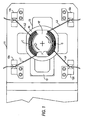
- FIGS. using a two-pole stator core 10 having a single coil wound on each pole as an exemplary workpiece.
- a pair of C-shaped chucks 13 within an exemplary wire-winding machine may hold stator core 10 during the wire coil winding process.
- One or both of chucks 13 may be movable.
- FIG. 1 shows, for example, movable left chuck 13 and fixed right chuck 13. It will, however, be understood that invention is equally applicable to stators having different pole and coil configurations, and to wire-winding machines that may use different or alternative mechanical configurations to hold in-process stators or other dynamo-electric machine components.
- FIG. 1 shows stator core 10 on whose poles a pair of wire coils C have been wound using a movable wire dispenser (not shown) in an wire-winding machine.
- Stator core 10 is held in a suitable orientation by chucks 13 in the stator core housing 11 of the wire-winding machine during the coil winding operations.
- Stator core 10 is shown in FIG. 1 after completion of the winding operations at a process stage in which starting and ending wire leads from the pair of wire coils C ((L2, L4) and (L1, L3), respectively) are secured to housing 11.
- Grippers 12a - 12d that are mounted on housing 11 are used to secure the wire leads L1 - L4.
- Grippers 12a - 12d may have any suitable mechanical configuration for releasably holding wire leads.
- the mechanical configuration may, for example, include resiliently biased opposing surfaces that are similar to those described in Santandrea et al. in U.S. Patents 5,137,221 and 5,288,088 to hold the wire leads.
- the wire coil winding process stage shown in FIG. 1 is similar to the process stage in conventional stator coil winding operations after which stator housing 11 in the conventional operations is moved from the wire-winding machine to a separately located termination station in preparation for terminating and connecting the wire leads to the stator terminals. See e.g., Luciani et al. U.S. Patents 5,065,503 and 5,245,748.
- wire lead termination operations may be carried out in the wire-winding machine itself, keeping stator 10 in the same location for both coil winding and wire lead termination processes.
- a wire-termination fixture or member may be used in conjunction with movable wire manipulators to terminate wound stator coil wire leads in situ.
- the wire-termination fixture and wire manipulator configuration may be structurally integrated into the wire-winding machine for this purpose.
- the wire manipulators may be any suitable manipulator that is capable of grasping and manipulating the coil lead wires.
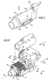
- These wire manipulators e.g., manipulator 26 FIG. 2 may, for example, be similar to those that are described in Luciani et al. U.S. patents 5,065,503 and 5,245,748.
- wire manipulator 26 may be disposed in the wire-winding machine on movable arms or guides (not shown).
- Wire manipulator 26 may be programmably moved in trajectories that are either parallel or perpendicular to the front face of housing 11, or both.
- Wire manipulator 26 may include conventional grasping mechanisms that allow the grasped wire to slide through as wire manipulator 26 moves parallel across the front face.
- wire manipulator 26 may be disposed on the movable arm so that it (manipulator 26) may rotate freely about its longitudinal axis Z. This free axial rotation may enable wire manipulator 26 to self-adjust and maintain its orientation with respect to a grasped wire at a substantially constant angle ( ⁇ ) while moving across the front face of housing 11.
- Wire manipulator 26 may be used to manipulate wire leads around the wire-termination fixture during the in situ wire lead termination processes or procedures.
- the wire-termination fixture may be used as a wire shaping form.
- FIG. 2 shows, for example, an exemplary wire-terminating fixture 22 (FIG. 3) that has been introduced from behind stator core 10 into the stator bore 10' and extends beyond the front face of stator core 10.
- FIG. 3 shows, for example, an exemplary wire-terminating fixture 22 (FIG. 3) that has been introduced from behind stator core 10 into the stator bore 10' and extends beyond the front face of stator core 10.
- wire-termination fixture 22 has a generally cylindrical shape.
- Wire- termination fixture 22 includes a main trunk portion 22a, a front extreme portion 22b, a rear attachment portion 22c, and key members 23 and 24.
- Attachment portion 22c may be used to suitably mount or attach wire-terminating fixture 22 to the wire-winding machine mechanisms so that wire-termination fixture 22 can be moved in or out of in-process stators.
- Attachment portion 22c is mechanically connected with main trunk portion 22a.
- the shape of main trunk portion 22a generally conforms in size and shape to stator bore 10' space between opposing stator poles P (on which coils C are wound).
- Key members 23 and 24 are disposed on the opposite sides of main trunk portion 22a. Key members 23 and 24 may be disposed in a suitable orientation so that when termination fixture 22 is inserted in bore 10' key members 23 and 24 occupy the outer annular space in bore 10' that is clear of pole faces P and wire coils C. Key member sides 23' and 24' deployed in that annular space may function as stops or restraints which confine wire stretches of wire coils C to the pole slots.
- Main trunk portion 22a extends or tapers into extreme portion 22b.
- Extreme portion 22b may, for example, have a generally cylindrical shape with a diameter that is smaller than of main trunk portion 22a.
- Both portions 22a and 22b may be fabricated from suitable solid or tubular materials.
- the combined length of the two portions may be suitably chosen to be longer than the length of stator poles P. With this combined length, extreme portion 22b protrudes from the front face of stator core 10 or extends beyond poles P; when termination member 22 is inserted through stator bore 10' (see e.g., FIG, 6).
- FIG. 2 shows, for example, lead wire L1 during the wire termination process after it has been grasped by wire manipulator 26, released from gripper 12a, and moved across a front plane of housing 11 to a position in which it is partially wrapped around extreme portion 22b.
- wire manipulator 26 may be programmed to grasp a lead wire (e.g., lead L1) at a spot in between coils C and the corresponding wire gripper (e.g., gripper 12a).
- wire manipulator 26 may be moved in a trajectory, which is perpendicularly away from a front plane or front face of housing 11, to pull grasped lead wire L1 out of corresponding gripper 12a.
- Conventional pulling of wound coil wire leads may tend to unravel wire coil C by pulling additional wire lengths or wire stretches from wound coil C.
- the pulling of an ending wire lead such as L1 or L3, which unlike starting wire leads L2 and L4 are not buried under wire coils C, may be particularly prone to unravelling wire coils C.
- key member side 23' acts as a restraining stop and prevents wire manipulator 26 from pulling additional wire lengths or wire stretches out of coil C even as it pulls lead wire L1 out of gripper 12a.
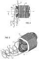
- FIG. 4 illustrates, for example, the partial wrapping of wire lead L1 around extreme portion 22b as wire manipulator 26 revolves around axis M.
- rear portions of key member 23 are omitted for clarity.
- the length of wire lead L1 extending from wire manipulator 26 to a contact point on extreme portion 22b may remain relatively constant even as manipulator 26 revolves around axis M because of the concentric geometry of extreme portion 22b and trajectory 25. As wire manipulator 26 moves along trajectory 25 and the contact point of wire lead L1 on extreme portion 22b shifts, lengths of grasped wire lead L1 slide through the grasping mechanism of wire manipulator 26 to compensate for the wire length wrapped around extreme portion 22b. Further, as wire manipulator 26 revolves round axis M it rotates (as indicated by rotation Z' FIG. 2) around its longitudinal axis Z.
- This self-adjusting rotation allows it (manipulator 26) to maintain a substantially constant angle ( ⁇ ) with respect to the portion of wire lead L1, which extends from wire manipulator 26 to the contact point on extreme portion 22b.
- the compensatory sliding of lead L1 and the self-adjusting rotation of wire manipulator 26 permit controlled wrapping of wire lead L1 around extreme portion 22b, and also avoid any undesirable wire entanglement around wire manipulator 26.
- the extent of wire manipulator 26 motion along circular trajectory 25 may be programmed to correspond to a predetermined wrapped length of wire lead L1 around extreme portion 22b. After the predetermined length of wire lead L1 is wrapped around extreme portion 22b, wire manipulator 26 may be activated to release grasped wire lead L1. If wire lead L1 is formed of suitably stiff or rigid wire, released wire lead L1 may retain its circular wrapped shape around extreme portion 22b without unravelling. The wrapping of lead L1 around extreme portion 22b deforms lead L1 to create or form a freestanding pattern conforming to the shape or geometry of extreme portion 22b.
- wire leads L2 - L4 which are anchored in grippers 12b - 12d, may be sequentially grasped one at a time by manipulator 26.
- the grasped wire leads are released from corresponding grippers 12b-12d, and wrapped around extreme portion 22b in a manner similar to that described for wire lead L1.
- the sequential manipulation of leads 11-14 may be used to physically stagger the placement of leads L1 - L4 on extreme portion 22b along axis M.
- key member sides (sides 23' and 24') function as restraints to prevent unravelling of wire stretches from wire coils C even as wire manipulator 26 pulls wire leads L2 - L4 out of corresponding grippers 12b-12d.
- termination fixture 22 may be withdrawn toward the rear of stator core 10 to complete the wire termination procedures. This withdrawal of termination fixture 22 causes extreme portion 22b to slide out from under wrapped portions of wire leads L1 - L4 leaving the leads suspended in front of stator core 10.
- FIG. 5 shows, for example, lead L1 - L4 suspended in front of stator core 10 after withdrawal of termination fixture 22 at the completion of the termination procedures. Suspended leads L1 - L4 are physically staggered along the longitudinal axis of stator core 10. Suspended leads L1 - L4 retain their deformed shapes, which were formed earlier by wrapping portions of the leads around extreme portion 22b, as freestanding patterns (i.e. closed circular loops) in them. It will be understood that in FIG.
- Stator core 10 with suspended coil leads L1 - L4 terminated in this manner may removed from the wire-winding machine and transferred to workstations or locations where the terminated leads may be physically connected to stator or dynamo-electric machine terminal boards or posts.
- the physical connection of the suspended lead wires L1 - L4 to terminal boards or posts may be suitably carried out at terminal connection workstations, for example, by human operators.
- FIG. 6 shows wire-termination fixture 22 in the same position relative to stator core 10 as shown in FIG. 2.
- Wire-termination fixture 22 is shown inserted in stator core 10.
- Key member 23 is seen disposed in the annular space adjacent to the edges of stator poles P.
- FIG. 6 certain components such as housing 11, wire coils C and leads L1 - L4 that are shown in FIG. 2 are omitted for clarity but certain additional machine components such as stator core pick and place device 50 are shown in greater detail.
- Pick and place device 50 includes movable pliers 51 and 52, which can hold stator core 10, for example, for removal from the wire winding machine after the wire termination procedures are completed.
- Wire - termination fixture 22 is mechanically attached to pick and place device 50 using, for example, bolt 54. Any suitable design or means may be used to align attached fixture 22 relative to device 50.
- Pick and place device 50 may, for example, include a centring seat to partially receive attachment portion 22c so that termination member 22 is centred around and extends along middle axis M between pliers 51 and 52. Middle axis M may be substantially coincident with the longitudinal axis of in-process stator core 10 held by chucks 13.
- Pliers 51 and 52 may hold in-process stator core 10 in position by contacting the opposite sides of stator core 10. Pliers 51 and 52 may move toward each other (in directions 53') to a closed or holding position in order to contact and hold stator core 10. Conversely, pliers 51 and 52 may move away from each other in directions 53'' to an open position to release a held stator core.
- C-shaped chucks 13 hold stator core 10 in housing 11 during the wire winding operations (which result in the formation of coils C) (FIG. 1).
- pick and place device 50 moves forward (opposite to direction 56 FIG. 6) to insert wire-termination fixture 22 into stator core 10 along axis M.
- pliers 51 and 52 are held in their open positions.
- pliers 51 and 52 extend into open spaces in C-shaped chucks 13 alongside but not in contact with the outer surfaces of stator core 10 (see FIG. 2).
- Pliers 51 and 52 are thus positioned in their open positions about stator core 10 ready to subsequently close and hold stator core 10 as necessary.
- pliers 51 and 52 may be moved to their closed positions to hold stator core 10. Chucks 13 may then be opened to release stator core 10, which is now safely held by pliers 51 and 52.
- pick and place device 50 may be retracted in direction 56 away from the front face of housing 11 (FIG. 2) carrying held stator core 10 out of housing 11. While pick and place device 50 holds stator core 10, termination fixture 22 remains in stator bore 10' such that extreme portion 22b continues to support wrapped portions of leads L1 - L4.
- Pick and place device 50 also may be provided with rotation capability so that it can rotate around axle 50'.
- Device 50 may be programmed to rotate around axle 50' to present stator core 10 in an orientation in which it (stator core) can be received or picked up by other conventional loading/unloading or transfer devices (not shown).
- the conventional transfer devices may have stator-holding mechanisms to grasp stator core 10 on free outer surfaces and receive stator core 10 from device 50.
- the conventional transfer devices may be used to place received stator core 10 in a transport pallet for movement to terminal connection workstations.
- Stator core 10 may be placed in the transport pallet in an orientation suitable or convenient for further processing at the terminal connection workstations.
- Stator 10 may, for example, be placed in the transport pallet vertically (i.e., with stator bore 10' vertically oriented) so that the terminated leads L1-L4 are on the upper stator face. This vertical orientation may, for example, provide a clear visual view and unhindered physical access to terminated leads L1 - L4 suitable for subsequent terminal connections by human operators.
- the conventional transfer device which receive stator core 10 from pick and place device 50 and the transport pallets that are used to carry stator core 10 to terminal connection work stations may optionally be provided with auxiliary support fixtures to support terminated leads L1 - L4 during transport.
- auxiliary support fixtures may be cylindrical structures that are similar in diameter to extreme portion 22b on which the terminated leads L1 - L4 are wrapped in the wire-winding machine.
- These cylindrical support structures may be disposed in an orientation parallel to the movement of the stator-holding mechanisms in the conventional transfer device.
- the support cylindrical structure disposed in the conventional transfer device may be aligned with extreme portion 22b to enable smooth receipt of the wrapped portions of leads L1 - L4.
- Wrapped portions of leads L1 - L4 may be transferred from extreme portion 22b to the cylindrical support structure by movement of the latter's stator-holding mechanisms parallel to the cylindrical support structure at the same time as same time as stator core 10 is transferred from device 50 to the conventional transfer device.
- stator cores 10 held in the conventional transfer device with leads L1 - L4 supported on the conventional transfer devices' cylindrical support structure may be transferred to the transport pallets with leads L1 - L4 supported on the latter's auxiliary support fixtures.
Abstract
Description
- The present invention relates to improved solutions for processing dynamo-electric machine components (e.g., armatures or stators for electric motors, generators, or alternators) through wire coil winding steps.
- Wire coils are an integral part of the dynamo-electric machine components such as armatures and stators. The wire coils are made of insulated wire wound on ferromagnetic poles. The ferromagnetic poles may be formed, for example, in the case of a stator, by adjacent longitudinal slots running along the inner surface of the stator core. The wound wire coil ends or leads are connected to terminal posts or boards on the component. In the operation of the dynamo-electric machine, electric voltage is applied to the terminal posts. As a result electric current passes through these wire coils generating electro-mechanical torques which cause the dynamo-electric machine armature to rotate. Wire coil-winding specifications (such as wire size, pitch, number of turns, and winding (pole) configuration) determine the operational rotational characteristics of the dynamo-electric machine.
- The dynamo-electric machine component wire coils are often wound using automated coil winding machinery that includes a wire dispenser or needle mounted on a moving arm, which dispenses wire drawn from a wire spool. Exemplary winders are described, for example, in commonly-assigned Santandrea et al. U.S. Patent 4,969,606, Santandrea et al. U.S. Patent 5,149,000, Santandrea et al. U.S. Patent 5,137,221, Santandrea et al. U.S. Patent 5,288,088 and, Stratico et al., U.S. Patent 5,257,745, and Stratico et al. U.S. Patent Application Publication US 2002/0020778, each of which is incorporated by reference in its entirety herein. For example, for winding stator coils, the automated machinery may be used to have the wire dispenser travel back and forth through the stator bore alongside a pole, dispensing wire stretches that are deposited on the pole sides and ends to form the stator coil to design specifications. After the coil is wound, wire leads from the starting and ending wire stretches of the stator wire coil may be cut to suitable lengths and terminated. The terminated wire leads are then routed along safe paths, which do not mechanically or electrically interfere with machine operation, and fastened or attached to terminal posts on the stator. Initially, the cut wire leads may be held in temporary positions secured by wire grippers while the stator core is being processed in the winding machinery. The wire termination and final routing and terminal attachment procedures are often carried out either manually or using automated wire termination and connection machines after the stator core has been moved out from the winding machinery.
- Unfortunately, conventional routing and attachment procedures may unwind, loosen, dislodge, or other wise degrade the wound wire coil. For example, pulling on the starting wire stretch, which is invariably buried under subsequent wire stretches, may dislodge or otherwise disturb the wound wire coil. An ending wire stretch that is loose or not held taut may cause the wound wire coil to unravel or unwind. Further, the handling of the starting and ending wire stretches may nick, scratch or otherwise damage wire insulation. Damaged wire insulation can lead to electrical shorts or leakage, which can degrade dynamo-electric machine performance or cause machine failure.
- Consideration is now being given to ways of providing solutions for improving dynamo-electric machine component manufacture. Attention is directed toward methods and apparatus for terminating stator wire coil leads, with a view to make wire lead routing and fastening procedures less disturbing to wound wire coils, and to improve the overall quality of dynamo-electric machine components.
- In accordance with the principles of the invention, methods and apparatus for the termination of dynamo-electric machine component wire coil lead portions are provided. The inventive methods and apparatus may be used for in situ wire lead termination in the automated wire winding machines in which the dynamo-electric machine component wire coils are formed.
- The wire-termination apparatus includes a shape -forming wire-termination fixture and a programmably movable wire manipulator. The wire manipulator may be any conventional wire manipulator that is capable of grasping and manipulating or moving the wound coil wire leads. The wire-termination fixture generally has a cylindrical shape. The wire-termination fixture and wire manipulator are structurally integrated into conventional dynamo-electric machine component coil wire-winding machines for in situ wire lead termination after the wire coils have been wound.
- In one embodiment applicable, for example, to the termination of stator wire coil leads, the wire-termination fixture includes a main trunk portion, a front extreme portion, a rear attachment portion, and key members. The attachment portion is used to attach or mount the wire-terminating fixture to movable components or mechanisms in the wire-winding machine. The main trunk and contiguous front extreme portion have cylindrical shapes, with the latter having a smaller diameter than the former. The main trunk portion generally conforms in size and shape to the stator bore spacing between opposing stator poles on which wire coils C are wound. The key members, which are disposed on the opposite sides of the main trunk portion, are designed to occupy the outer annular space in the stator bore that is clear of the stator poles. The key member sides function as restraints that confine stator wire coil stretches to the pole slots. The combined length of the wire-termination fixture is such that the extreme portion protrudes from the front face of the stator and extends beyond the stator poles when the fixture is inserted through the bore of an in-process stator.
- In operation the wire-terminating fixture is inserted in the stator bore from the rear after wire coils have been wound on the stator poles. The extreme portion of inserted wire-terminating fixture protrudes out of the front face of the stator and extends beyond the stator poles. Using the wire manipulator the wound coil wire leads are grasped and wrapped around the shape-forming fixture to give them deformed shapes that are suitable for wire termination. Key member sides of the inserted wire-termination member prevent the stator wire coils from unraveling during the wrapping process. The wire lead deformation is designed to produce freestanding geometrical patterns in the terminated wire leads. The freestanding geometrical patterns may have shapes (e.g., circular loops) conforming to the shape of the wire-termination fixture on which the wire leads are wrapped. Next, the wire-termination fixture is withdrawn from the stator bore leaving the terminated wire leads with the freestanding patterns suspended in the front of the stator. Stators with terminated coil wire leads suspended about the front face can then be removed from the wire-winding machine for further processing, for example, at terminal connection workstations.
- Further features of the invention, its nature, and various advantages will be more apparent from the following detailed description of the preferred embodiments and the accompanying drawings, wherein like reference characters represent like elements throughout, and in which:
- FIG. 1 is a side elevation view of a stator core held in an automated wire-winding machine that includes a wire-termination fixture, in accordance with the principles of the present invention. The stator core is shown at an illustrative step in the wire coil winding process at which wound coil wire leads are held in temporary anchoring grippers. The wire-termination fixture is not seen at this process step in this view.
- FIG. 2 is a similar side elevation view of the stator core held in the automated wire winder machine of FIG. 1 at a subsequent process step at which the wire termination fixture has been inserted in the stator bore in accordance with the principles of the present invention.
- FIG. 3 is a perspective view of the wire
termination fixture of FIG. 2, as seen from
direction 3 in FIG. 2. - FIG. 4 is another view of the wire-termination fixture as seen from line 4-4 of FIG. 2. Portions of the winding machine housing have been omitted to show the details of the disposition of the wire termination fixture relative to the stator core.
- FIG. 5 is a perspective view of the stator core after the stator coil wire leads have been terminated in accordance with the principles of the present invention.
- FIG. 6 is another view of the wire-termination
fixture as seen
direction 3 of FIG. 2. Portions of the winding machine housing have been omitted to show the wire-termination fixture details. Further details of the attachment of the wire-termination fixture to a component pick and place device are shown. - In several of the accompanying drawings, which show sectional views, hatching or shading of various sectional elements may have been omitted for clarity. It will be understood that this omission of hatching or shading in the drawings is for the purpose of clarity in illustration only.
-
- The present disclosure provides solutions for uniform and reproducible manufacturing of dynamo-electric machine components. A disclosed solution concerns methods and apparatus for the termination of stator coil wire lead portions, which may then be physically routed and attached to one or more terminals mounted on the stator core. The terminals may, for example, be the electrical current or voltage supply terminals of the dynamo electric machine in which the stator is used. The terminated coil leads may be physically positioned along suitable paths, which do not interfere with the operation of the dynamo-electric machine.
- The inventive wire-termination apparatus and fixtures may be integrated with or built into conventional wire coil winding machines so that the wire termination steps may be accomplished in the same machine or workstation as the wire coil winding. Alternatively, the inventive wire-termination apparatus may be used at subsequent workstation. In order that the invention herein described can be fully understood, the subsequent description is set forth in the context of the manufacture of stators. It will, however, be understood that the invention is equally applicable to other types of dynamo-electric machine components.
- Exemplary stator coil winding machines in which the inventive methods and apparatus may be used generally include a stator housing and contain mechanical chucks to hold in-process stators as wire coils are wound on the stator poles. (See e.g., Santandrea et al. U.S. Patents 4,969,606, and 5,149, 000). The stator housing may further include wire grippers or other means that can be used to temporarily hold and present wire coil leads in a an orientation suitable for futher operations after the wire coils are wound. The wire grippers may, for example, be similar to those disclosed in Santandrea et al. U.S. Patent 5,137,221 or Santandrea et al. U.S. Patent 5,288,088, both of which are incorporated by reference herein.
- In order that the invention herein described may be easily understood, the subsequent description is set forth with reference to the FIGS. using a two-
pole stator core 10 having a single coil wound on each pole as an exemplary workpiece. A pair of C-shapedchucks 13 within an exemplary wire-winding machine may holdstator core 10 during the wire coil winding process. One or both ofchucks 13 may be movable. FIG. 1 shows, for example, movableleft chuck 13 and fixedright chuck 13. It will, however, be understood that invention is equally applicable to stators having different pole and coil configurations, and to wire-winding machines that may use different or alternative mechanical configurations to hold in-process stators or other dynamo-electric machine components. - FIG. 1 shows
stator core 10 on whose poles a pair of wire coils C have been wound using a movable wire dispenser (not shown) in an wire-winding machine.Stator core 10 is held in a suitable orientation bychucks 13 in thestator core housing 11 of the wire-winding machine during the coil winding operations.Stator core 10 is shown in FIG. 1 after completion of the winding operations at a process stage in which starting and ending wire leads from the pair of wire coils C ((L2, L4) and (L1, L3), respectively) are secured tohousing 11.Grippers 12a - 12d that are mounted onhousing 11 are used to secure the wire leads L1 - L4.Grippers 12a - 12d may have any suitable mechanical configuration for releasably holding wire leads. The mechanical configuration may, for example, include resiliently biased opposing surfaces that are similar to those described in Santandrea et al. in U.S. Patents 5,137,221 and 5,288,088 to hold the wire leads. - The wire coil winding process stage shown in FIG. 1 is similar to the process stage in conventional stator coil winding operations after which stator
housing 11 in the conventional operations is moved from the wire-winding machine to a separately located termination station in preparation for terminating and connecting the wire leads to the stator terminals. See e.g., Luciani et al. U.S. Patents 5,065,503 and 5,245,748. - In the inventive method described herein the wire lead termination operations may be carried out in the wire-winding machine itself, keeping
stator 10 in the same location for both coil winding and wire lead termination processes. A wire-termination fixture or member may be used in conjunction with movable wire manipulators to terminate wound stator coil wire leads in situ. The wire-termination fixture and wire manipulator configuration may be structurally integrated into the wire-winding machine for this purpose. - The wire manipulators may be any suitable manipulator that is capable of grasping and manipulating the coil lead wires. These wire manipulators (e.g.,
manipulator 26 FIG. 2) may, for example, be similar to those that are described in Luciani et al. U.S. patents 5,065,503 and 5,245,748. With reference to FIG. 2,wire manipulator 26 may be disposed in the wire-winding machine on movable arms or guides (not shown).Wire manipulator 26 may be programmably moved in trajectories that are either parallel or perpendicular to the front face ofhousing 11, or both.Wire manipulator 26 may include conventional grasping mechanisms that allow the grasped wire to slide through aswire manipulator 26 moves parallel across the front face. Further,wire manipulator 26 may be disposed on the movable arm so that it (manipulator 26) may rotate freely about its longitudinal axis Z. This free axial rotation may enablewire manipulator 26 to self-adjust and maintain its orientation with respect to a grasped wire at a substantially constant angle () while moving across the front face ofhousing 11.Wire manipulator 26 may be used to manipulate wire leads around the wire-termination fixture during the in situ wire lead termination processes or procedures. The wire-termination fixture may be used as a wire shaping form. - FIG. 2 shows, for example, an exemplary wire-terminating fixture 22 (FIG. 3) that has been introduced from behind
stator core 10 into the stator bore 10' and extends beyond the front face ofstator core 10. - With reference to FIGS. 2 - 4, wire-
termination fixture 22 has a generally cylindrical shape. Wire-termination fixture 22 includes amain trunk portion 22a, a frontextreme portion 22b, arear attachment portion 22c, andkey members Attachment portion 22c may be used to suitably mount or attach wire-terminatingfixture 22 to the wire-winding machine mechanisms so that wire-termination fixture 22 can be moved in or out of in-process stators.Attachment portion 22c is mechanically connected withmain trunk portion 22a. The shape ofmain trunk portion 22a generally conforms in size and shape to stator bore 10' space between opposing stator poles P (on which coils C are wound). -
Key members main trunk portion 22a.Key members termination fixture 22 is inserted in bore 10'key members -
Main trunk portion 22a extends or tapers intoextreme portion 22b.Extreme portion 22b may, for example, have a generally cylindrical shape with a diameter that is smaller than ofmain trunk portion 22a. Bothportions extreme portion 22b protrudes from the front face ofstator core 10 or extends beyond poles P; whentermination member 22 is inserted through stator bore 10' (see e.g., FIG, 6). - The in-situ wire termination method may be further understood with reference to FIGS. 2 -6. FIG. 2 shows, for example, lead wire L1 during the wire termination process after it has been grasped by
wire manipulator 26, released fromgripper 12a, and moved across a front plane ofhousing 11 to a position in which it is partially wrapped aroundextreme portion 22b. In arriving at the wire positions similar to those shown in FIG. 2, at a first step in the termination process,wire manipulator 26 may be programmed to grasp a lead wire (e.g., lead L1) at a spot in between coils C and the corresponding wire gripper (e.g.,gripper 12a). Thenwire manipulator 26 may be moved in a trajectory, which is perpendicularly away from a front plane or front face ofhousing 11, to pull grasped lead wire L1 out ofcorresponding gripper 12a. Conventional pulling of wound coil wire leads may tend to unravel wire coil C by pulling additional wire lengths or wire stretches from wound coil C. The pulling of an ending wire lead such as L1 or L3, which unlike starting wire leads L2 and L4 are not buried under wire coils C, may be particularly prone to unravelling wire coils C. However, here key member side 23' acts as a restraining stop and preventswire manipulator 26 from pulling additional wire lengths or wire stretches out of coil C even as it pulls lead wire L1 out ofgripper 12a. - Further circular or revolving movement of
wire manipulator 26 along acircular trajectory 25 about stator core centre 10'' wraps grasped wire lead L1 aroundextreme portion 22b oftermination member 22. FIG. 4 illustrates, for example, the partial wrapping of wire lead L1 aroundextreme portion 22b aswire manipulator 26 revolves around axis M. In FIG. 4 rear portions ofkey member 23 are omitted for clarity. - The length of wire lead L1 extending from
wire manipulator 26 to a contact point onextreme portion 22b may remain relatively constant even asmanipulator 26 revolves around axis M because of the concentric geometry ofextreme portion 22b andtrajectory 25. Aswire manipulator 26 moves alongtrajectory 25 and the contact point of wire lead L1 onextreme portion 22b shifts, lengths of grasped wire lead L1 slide through the grasping mechanism ofwire manipulator 26 to compensate for the wire length wrapped aroundextreme portion 22b. Further, aswire manipulator 26 revolves round axis M it rotates (as indicated by rotation Z' FIG. 2) around its longitudinal axis Z. This self-adjusting rotation allows it (manipulator 26) to maintain a substantially constant angle () with respect to the portion of wire lead L1, which extends fromwire manipulator 26 to the contact point onextreme portion 22b. The compensatory sliding of lead L1 and the self-adjusting rotation ofwire manipulator 26 permit controlled wrapping of wire lead L1 aroundextreme portion 22b, and also avoid any undesirable wire entanglement aroundwire manipulator 26. - The extent of
wire manipulator 26 motion alongcircular trajectory 25 may be programmed to correspond to a predetermined wrapped length of wire lead L1 aroundextreme portion 22b. After the predetermined length of wire lead L1 is wrapped aroundextreme portion 22b,wire manipulator 26 may be activated to release grasped wire lead L1. If wire lead L1 is formed of suitably stiff or rigid wire, released wire lead L1 may retain its circular wrapped shape aroundextreme portion 22b without unravelling. The wrapping of lead L1 aroundextreme portion 22b deforms lead L1 to create or form a freestanding pattern conforming to the shape or geometry ofextreme portion 22b. - Next the remaining wire leads L2 - L4, which are anchored in
grippers 12b - 12d, may be sequentially grasped one at a time bymanipulator 26. The grasped wire leads are released from correspondinggrippers 12b-12d, and wrapped aroundextreme portion 22b in a manner similar to that described for wire lead L1. The sequential manipulation of leads 11-14 may be used to physically stagger the placement of leads L1 - L4 onextreme portion 22b along axis M. As described earlier in the context of wrapping wire lead L1, key member sides (sides 23' and 24') function as restraints to prevent unravelling of wire stretches from wire coils C even aswire manipulator 26 pulls wire leads L2 - L4 out ofcorresponding grippers 12b-12d. - After all of the starting and ending wire coil leads L1 - L4 have been sequentially released from
grippers 12a - 12d, and wrapped around the cylindrical surface ofextreme portion 22b,termination fixture 22 may be withdrawn toward the rear ofstator core 10 to complete the wire termination procedures. This withdrawal oftermination fixture 22 causesextreme portion 22b to slide out from under wrapped portions of wire leads L1 - L4 leaving the leads suspended in front ofstator core 10. - For wire leads L1 - L4 made of stiff or rigid material the wrapped portions of leads L1 -L4 retain deformed shapes that conform to the geometry of
extreme portion 22b even after the latter has been slid out or withdrawn. FIG. 5 shows, for example, lead L1 - L4 suspended in front ofstator core 10 after withdrawal oftermination fixture 22 at the completion of the termination procedures. Suspended leads L1 - L4 are physically staggered along the longitudinal axis ofstator core 10. Suspended leads L1 - L4 retain their deformed shapes, which were formed earlier by wrapping portions of the leads aroundextreme portion 22b, as freestanding patterns (i.e. closed circular loops) in them. It will be understood that in FIG. 5, the physically staggering or separation between leads L1 - L4 along the stator axis has been exaggerated for purposes of clarity in illustration. It will be further understood that the particular closed circular wire loop patterns in terminated leads L1 - L4 are chosen for purposes of illustration only. Other equally useful shapes or patterns for terminating wire coil leads may be obtained, for example, by suitable choice of terminating fixture (e.g., fixture 22) shape or geometry, and by suitable choice of the geometry and length of the trajectory (e.g., trajectory 25) along which the wire leads are moved. -
Stator core 10 with suspended coil leads L1 - L4 terminated in this manner (as shown, for example, in FIG. 5) may removed from the wire-winding machine and transferred to workstations or locations where the terminated leads may be physically connected to stator or dynamo-electric machine terminal boards or posts. The physical connection of the suspended lead wires L1 - L4 to terminal boards or posts may be suitably carried out at terminal connection workstations, for example, by human operators. - In a further embodiment of the present invention the mechanics of removing
stator core 10 out of the wire-winding machine, and the mechanics of inserting and withdrawing wire-termination fixture 22 fromstator core 10 during the in-situ wire termination procedures may be combined or integrated. This integrated operation may be understood with reference to FIG. 6. FIG. 6 shows wire-termination fixture 22 in the same position relative tostator core 10 as shown in FIG. 2. Wire-termination fixture 22 is shown inserted instator core 10.Key member 23 is seen disposed in the annular space adjacent to the edges of stator poles P. However, in FIG. 6 certain components such ashousing 11, wire coils C and leads L1 - L4 that are shown in FIG. 2 are omitted for clarity but certain additional machine components such as stator core pick andplace device 50 are shown in greater detail. - Pick and
place device 50 includesmovable pliers stator core 10, for example, for removal from the wire winding machine after the wire termination procedures are completed. Wire -termination fixture 22 is mechanically attached to pick andplace device 50 using, for example,bolt 54. Any suitable design or means may be used to align attachedfixture 22 relative todevice 50. Pick andplace device 50 may, for example, include a centring seat to partially receiveattachment portion 22c so thattermination member 22 is centred around and extends along middle axis M betweenpliers process stator core 10 held bychucks 13. -
Pliers process stator core 10 in position by contacting the opposite sides ofstator core 10.Pliers stator core 10. Conversely,pliers - C-shaped
chucks 13hold stator core 10 inhousing 11 during the wire winding operations (which result in the formation of coils C) (FIG. 1). At the start of wire termination procedures, pick andplace device 50 moves forward (opposite todirection 56 FIG. 6) to insert wire-termination fixture 22 intostator core 10 along axis M. During thisforward movement pliers termination fixture 22 is inserted in stator bore 10,pliers chucks 13 alongside but not in contact with the outer surfaces of stator core 10 (see FIG. 2).Pliers stator core 10 ready to subsequently close and holdstator core 10 as necessary. - After the wire termination steps in which leads L1 - L4 are disengaged from
grippers 12a-12d and wrapped aroundextreme portion 22b, as described previously,pliers stator core 10.Chucks 13 may then be opened to releasestator core 10, which is now safely held bypliers place device 50 may be retracted indirection 56 away from the front face of housing 11 (FIG. 2) carrying heldstator core 10 out ofhousing 11. While pick andplace device 50 holdsstator core 10,termination fixture 22 remains in stator bore 10' such thatextreme portion 22b continues to support wrapped portions of leads L1 - L4. - Pick and
place device 50 also may be provided with rotation capability so that it can rotate around axle 50'.Device 50 may be programmed to rotate around axle 50' to presentstator core 10 in an orientation in which it (stator core) can be received or picked up by other conventional loading/unloading or transfer devices (not shown). The conventional transfer devices may have stator-holding mechanisms to graspstator core 10 on free outer surfaces and receivestator core 10 fromdevice 50. The conventional transfer devices may be used to place receivedstator core 10 in a transport pallet for movement to terminal connection workstations. -
Stator core 10 may be placed in the transport pallet in an orientation suitable or convenient for further processing at the terminal connection workstations.Stator 10 may, for example, be placed in the transport pallet vertically (i.e., with stator bore 10' vertically oriented) so that the terminated leads L1-L4 are on the upper stator face. This vertical orientation may, for example, provide a clear visual view and unhindered physical access to terminated leads L1 - L4 suitable for subsequent terminal connections by human operators. - The conventional transfer device which receive
stator core 10 from pick andplace device 50 and the transport pallets that are used to carrystator core 10 to terminal connection work stations may optionally be provided with auxiliary support fixtures to support terminated leads L1 - L4 during transport. These auxiliary support fixtures may be cylindrical structures that are similar in diameter toextreme portion 22b on which the terminated leads L1 - L4 are wrapped in the wire-winding machine. These cylindrical support structures may be disposed in an orientation parallel to the movement of the stator-holding mechanisms in the conventional transfer device. In operation, for example, in the transfer ofstator core 10 from pick andplace device 50, the support cylindrical structure disposed in the conventional transfer device may be aligned withextreme portion 22b to enable smooth receipt of the wrapped portions of leads L1 - L4. Wrapped portions of leads L1 - L4 may be transferred fromextreme portion 22b to the cylindrical support structure by movement of the latter's stator-holding mechanisms parallel to the cylindrical support structure at the same time as same time asstator core 10 is transferred fromdevice 50 to the conventional transfer device. In similar fashion,stator cores 10 held in the conventional transfer device with leads L1 - L4 supported on the conventional transfer devices' cylindrical support structure may be transferred to the transport pallets with leads L1 - L4 supported on the latter's auxiliary support fixtures. - One skilled in the art will appreciate that the present invention can be practiced by other than the described embodiments, which are presented for purposes of illustration and not of limitation. It will be understood that terms like "forward" and "backward", "front" and "rear", and other directional or orientational terms are used herein only for convenience, and that no fixed or absolute orientations are intended by the use of these terms.
Claims (26)
- A wire-winding machine comprising:a movable wire dispenser for winding wire coils on the poles of a dynamo-electric machine component;means for presenting wire leads of said wound wire coils temporarily positioned with respect to said wire coils;a shape-forming fixture disposed in said machine; anda wire manipulator for grasping and manipulating said wire leads along trajectories around said shape-forming fixture.
- The wire-winding machine of claim 1 wherein said shape-forming fixture comprises an attachment portion for attaching said shape-forming fixture to a component pick and place device in said wire-winding machine.
- The wire-winding machine of claim 1 wherein said shape-forming fixture is disposed relative to said dynamo-machine component so that a portion of said fixture protrudes from a front plane of said dynamo-machine component.
- The wire-winding machine of claim 1 wherein said shape-forming fixture comprises a cylindrical structure.
- The wire-winding machine of claim 1 wherein said shape-forming fixture comprises a structure for restraining movement of wires in said wound wire coils while said wire manipulator is manipulating said wire leads.
- The wire-winding machine of claim 1 wherein said dynamo-electric machine component is a stator and wherein said shape-forming fixture comprises:a main trunk portion having a generally cylindrical shape conforming to the bore space of said stator between said poles;an extreme portion attached to said main trunk portion, wherein said extreme portion has a diameter that is smaller than the diameter of said main trunk portion, wherein said extreme portion extends beyond said poles when said fixture is inserted in the bore of said stator.
- The wire-winding machine of claim 6 wherein said shape-forming fixture further comprises a key member disposed on a side of said main trunk portion, wherein said key member occupies the annular space that is adjacent to said stator poles in said stator bore when said shape-forming fixture is inserted in said stator bore.
- The wire-winding machine of claim 2 wherein said component pick and place device comprises movable pliers for holding a stator.
- The wire-winding machine of claim 1 wherein said wire manipulator comprises:a grasping mechanism mounted on a movable arm that can be moved with respect to the front plane of said dynamo-electric machine component.
- The wire-winding machine of claim 9 wherein said grasping mechanism is mounted on said movable arm so that said grasping mechanism can freely rotate around its longitudinal axis Z.
- The wire-winding machine of claim 9 wherein said movable arm can move in trajectories around a longitudinal axis of said dynamo-electric machine component.
- The wire-winding machine of claim 1 or 3 wherein said trajectories are designed to deform said wire leads against said shape-forming fixture to form freestanding patterns in said wire leads.
- The wire-winding machine of claim 12 wherein said freestanding patterns include a wire loop.
- The wire-winding machine of claim 12 wherein said trajectories are designed to form said freestanding patterns that are physically staggered along an axis of said dynamo-electric machine component.
- A method for terminating wire coil leads in situ in a wire-winding machine that is used to wind wire coils on the poles of a dynamo-electric machine component comprising:presenting wound coil wire leads temporarily positioned with respect to said wire coils;disposing a shape-forming fixture about the front plane of said dynamo-electric machine component; andusing a wire manipulator to grasp and manipulate said wire leads along predetermined trajectories around said shape-forming fixture.
- The method of claim 15 wherein disposing a shape-forming fixture comprises disposing said shape-forming fixture that includes a structure for restraining movement of wires in said wound wire coils while said wire manipulator is manipulating said wire leads.
- The method of claim 15 wherein said dynamo-electric machine component is a stator, wherein disposing a shape-forming fixture comprises inserting said shape-forming fixture in a bore of said stator and that said shape-forming fixture includes:a main trunk portion having a generally cylindrical shape conforming to the bore space of said stator between said poles;an extreme portion attached to said main trunk portion, wherein said extreme portion has a diameter that is smaller than the diameter of said main trunk portion, and wherein said extreme portion extends beyond said poles when said fixture is inserted in the bore of said stator.
- The method of claim 17 wherein disposing said shape-forming fixture further includes disposing a key member disposed on a side of said main trunk portion, wherein said key member occupies the annular space that is adjacent to said stator poles in said stator bore when said shape-forming fixture is inserted in said stator bore.
- The method of claim 15 wherein said using said wire manipulator comprises:using a grasping mechanism mounted on a movable arm that can move with respect to the front face of said dynamo-electric machine component.
- The method of claim 19 wherein using said grasping mechanism further comprises using a mechanism that allows grasped wire to slide through as said movable arm moves with respect to said front face of said dynamo-electric machine component.
- The method of claim 19 wherein using said grasping mechanism further comprises using a grasping mechanism that is mounted on said movable arm so that said grasping mechanism can freely rotate around its longitudinal axis Z.
- The method of claim 19 wherein using said grasping mechanism further comprises causing said movable arm to move in a circular trajectory around a longitudinal axis of said dynamo-electric machine component.
- The method of claim 15 wherein said manipulating of said wire leads around said shape-forming fixture comprises deforming said wire leads to form freestanding patterns conforming to a surface of said shape-forming fixture.
- The method of claim 23 wherein said freestanding patterns comprise loops.
- The method of claim 15 wherein said manipulating of said wire leads around said shape-forming fixture comprises sequentially deforming said wire leads to form freestanding patterns that are physically staggered along a longitudinal axis of said dynamo-electric machine component.
- The method of claim 15 further comprising separating said shape-forming fixture and said deformed wire leads leaving said deformed wire leads with freestanding patterns suspended about a front face of said dynamo-electric machine component.
Applications Claiming Priority (4)
| Application Number | Priority Date | Filing Date | Title |
|---|---|---|---|
| 1998-12-15 | |||
| US33853201P | 2001-11-06 | 2001-11-06 | |
| US338532P | 2001-11-06 | ||
| US10/288,640 US6923399B1 (en) | 2001-11-06 | 2002-11-04 | Manufacturing methods and apparatus for terminating dynamo-machine component wire coil leads |
Publications (2)
| Publication Number | Publication Date |
|---|---|
| EP1309072A2 true EP1309072A2 (en) | 2003-05-07 |
| EP1309072A3 EP1309072A3 (en) | 2006-04-26 |
Family
ID=26965142
Family Applications (1)
| Application Number | Title | Priority Date | Filing Date |
|---|---|---|---|
| EP02024703A Withdrawn EP1309072A3 (en) | 2001-11-06 | 2002-11-06 | Method and apparatus for terminating coil leads of dynamo-electric machine |
Country Status (3)
| Country | Link |
|---|---|
| US (1) | US6923399B1 (en) |
| EP (1) | EP1309072A3 (en) |
| CA (1) | CA2411266A1 (en) |
Cited By (4)
| Publication number | Priority date | Publication date | Assignee | Title |
|---|---|---|---|---|
| WO2008055636A1 (en) * | 2006-11-06 | 2008-05-15 | Atop S.P.A. | Method and apparatus for terminating leads of plural wires in dynamo electric machine core |
| CN101536291B (en) * | 2006-11-06 | 2011-12-14 | Atop有限公司 | Method and apparatus for terminating leads of plural wires in dynamo electric machine core |
| CN104518619A (en) * | 2013-09-27 | 2015-04-15 | 宁波名晟电机科技有限公司 | Motor internal wire spool and wiring method |
| EP3211773B1 (en) * | 2016-02-25 | 2021-07-28 | Audi AG | Method for the production of a stator by pin winding |
Families Citing this family (2)
| Publication number | Priority date | Publication date | Assignee | Title |
|---|---|---|---|---|
| JP5641366B2 (en) * | 2012-01-25 | 2014-12-17 | 株式会社デンソー | Stator and stator manufacturing method |
| CN109861048A (en) * | 2019-03-29 | 2019-06-07 | 北京理工大学 | Harness winding robot |
Citations (5)
| Publication number | Priority date | Publication date | Assignee | Title |
|---|---|---|---|---|
| EP0469426A2 (en) * | 1990-08-01 | 1992-02-05 | AXIS S.p.A. | Methods and apparatus for connecting stator coil leads |
| US5618007A (en) * | 1990-09-25 | 1997-04-08 | Globe Products Inc. | Stator winding apparatus |
| US5755021A (en) * | 1995-07-07 | 1998-05-26 | Globe Products Inc. | Stator lead wire connecting method |
| US5950300A (en) * | 1996-10-28 | 1999-09-14 | Globe Products Inc. | Stator coil lead termination method and apparatus |
| US6141864A (en) * | 1998-01-15 | 2000-11-07 | Trw Inc. | Motor stator winding tool |
Family Cites Families (10)
| Publication number | Priority date | Publication date | Assignee | Title |
|---|---|---|---|---|
| IT1219093B (en) | 1988-03-10 | 1990-04-24 | Axis Spa | WRAPPING MACHINE FOR BIPOLAR STATORS |
| US5149000A (en) | 1988-03-10 | 1992-09-22 | Axis S.P.A. | Machine for winding two-pole stators |
| US5233751A (en) * | 1990-05-25 | 1993-08-10 | Axis U.S.A., Inc. | Method and apparatus for connecting intermediate stator coil leads |
| US5137221A (en) | 1990-10-04 | 1992-08-11 | Axis Usa, Inc. | Rapidly changeable chucks for holding stators in stator processing apparatus |
| US5257745A (en) | 1990-11-09 | 1993-11-02 | Axis Usa, Inc. | Apparatus for facilitating the changing of shrouds in armature winding machines |
| US5485670A (en) * | 1993-08-30 | 1996-01-23 | Alliance Winding Equipment, Inc. | Stator coil lacing machine |
| US5535503A (en) * | 1993-12-03 | 1996-07-16 | Globe Products Inc. | Stator lead wire connection method and apparatus |
| US6108897A (en) * | 1997-09-18 | 2000-08-29 | Globe Products Inc. | Stator coil finish lead positioning |
| JP3380885B2 (en) * | 2000-05-25 | 2003-02-24 | 株式会社林工業所 | Winding method and winding device for motor stator |
| MXPA03003258A (en) * | 2000-10-16 | 2004-12-03 | Globe Motors Inc | Machine for winding dynamo-electric stators. |
-
2002
- 2002-11-04 US US10/288,640 patent/US6923399B1/en not_active Expired - Fee Related
- 2002-11-06 EP EP02024703A patent/EP1309072A3/en not_active Withdrawn
- 2002-11-06 CA CA002411266A patent/CA2411266A1/en not_active Abandoned
Patent Citations (5)
| Publication number | Priority date | Publication date | Assignee | Title |
|---|---|---|---|---|
| EP0469426A2 (en) * | 1990-08-01 | 1992-02-05 | AXIS S.p.A. | Methods and apparatus for connecting stator coil leads |
| US5618007A (en) * | 1990-09-25 | 1997-04-08 | Globe Products Inc. | Stator winding apparatus |
| US5755021A (en) * | 1995-07-07 | 1998-05-26 | Globe Products Inc. | Stator lead wire connecting method |
| US5950300A (en) * | 1996-10-28 | 1999-09-14 | Globe Products Inc. | Stator coil lead termination method and apparatus |
| US6141864A (en) * | 1998-01-15 | 2000-11-07 | Trw Inc. | Motor stator winding tool |
Non-Patent Citations (1)
| Title |
|---|
| BODEN R: "AUTOMATISCHE POSITIONIERUNG LOSER WICKLUNGSDRAHTENDEN BEWICKELTER STATOREN" ANTRIEBSTECHNIK, VEREINIGTE FACHVERLAGE, MAINZ, DE, vol. 31, no. 9, 1 September 1992 (1992-09-01), pages 84-87, XP000291684 ISSN: 0722-8546 * |
Cited By (6)
| Publication number | Priority date | Publication date | Assignee | Title |
|---|---|---|---|---|
| WO2008055636A1 (en) * | 2006-11-06 | 2008-05-15 | Atop S.P.A. | Method and apparatus for terminating leads of plural wires in dynamo electric machine core |
| CN101536291B (en) * | 2006-11-06 | 2011-12-14 | Atop有限公司 | Method and apparatus for terminating leads of plural wires in dynamo electric machine core |
| US8468686B2 (en) | 2006-11-06 | 2013-06-25 | Atop S.P.A. | Apparatus for terminating leads of plural wires in dynamo electric machine core |
| US8893374B2 (en) | 2006-11-06 | 2014-11-25 | Atop S.P.A. | Method for terminating leads of plural wires in dynamo electric machine core |
| CN104518619A (en) * | 2013-09-27 | 2015-04-15 | 宁波名晟电机科技有限公司 | Motor internal wire spool and wiring method |
| EP3211773B1 (en) * | 2016-02-25 | 2021-07-28 | Audi AG | Method for the production of a stator by pin winding |
Also Published As
| Publication number | Publication date |
|---|---|
| CA2411266A1 (en) | 2003-05-06 |
| US6923399B1 (en) | 2005-08-02 |
| EP1309072A3 (en) | 2006-04-26 |
Similar Documents
| Publication | Publication Date | Title |
|---|---|---|
| EP0481769B1 (en) | Stator coil winding and lead termination method and apparatus | |
| US5535503A (en) | Stator lead wire connection method and apparatus | |
| US7779536B2 (en) | Apparatus for wire coil lead placement in machinery for producing dynamo electric machine components | |
| EP0411275B1 (en) | Methods and apparatus for making stators for electric motors and the like, and improved terminal boards therefor | |
| CN109075673B (en) | Winding device and winding method | |
| US20040011911A1 (en) | Wire winding apparatus for dynamo-electric components | |
| US5341997A (en) | Two-wire stator winding machine | |
| US6601288B2 (en) | Production of dynamo-electric machine stator coils having leads at final attachment points before insertion into a stator core | |
| US6923399B1 (en) | Manufacturing methods and apparatus for terminating dynamo-machine component wire coil leads | |
| CN100477453C (en) | Wire winder and wire winding method | |
| US5291649A (en) | Methods and apparatus for processing stators | |
| US5947404A (en) | Stator winding method and apparatus | |
| WO1997042698A9 (en) | Stator winding method and apparatus | |
| JP4403714B2 (en) | Coil formation insertion device and coil formation insertion method | |
| US5802706A (en) | Apparatus for injecting stator winding coil groups into a stator core | |
| WO1998039835A1 (en) | Stator manufacturing method and apparatus | |
| US3942246A (en) | Method of making armature windings for commutator type dynamo-electric machines | |
| US4037320A (en) | Apparatus for forming armature windings for commutator type dynamo/electric machines | |
| EP1061634A1 (en) | Method and apparatus for placing wire coils with varied lengths on dynamo electric motor stators | |
| EP0453311B2 (en) | Method and apparatus for inserting stator coil lead wires into terminals having wire-receiving channels | |
| KR102661986B1 (en) | Method and apparatus for manufacturing rotors and stators, including manufacturing of connecting wires | |
| US6612519B1 (en) | Methods and apparatus for winding electric machine cores | |
| US6343762B1 (en) | Winders for electric motor armatures | |
| US6705008B1 (en) | System and method for sleeving a lead wire | |
| MXPA96003524A (en) | Systems, methods and apparatus for injecting groups of winding coils for injection stator in a nucleus of this |
Legal Events
| Date | Code | Title | Description |
|---|---|---|---|
| PUAI | Public reference made under article 153(3) epc to a published international application that has entered the european phase |
Free format text: ORIGINAL CODE: 0009012 |
|
| AK | Designated contracting states |
Designated state(s): AT BE BG CH CY CZ DE DK EE ES FI FR GB GR IE IT LI LU MC NL PT SE SK TR |
|
| AX | Request for extension of the european patent |
Extension state: AL LT LV MK RO SI |
|
| PUAL | Search report despatched |
Free format text: ORIGINAL CODE: 0009013 |
|
| AK | Designated contracting states |
Kind code of ref document: A3 Designated state(s): AT BE BG CH CY CZ DE DK EE ES FI FR GB GR IE IT LI LU MC NL PT SE SK TR |
|
| AX | Request for extension of the european patent |
Extension state: AL LT LV MK RO SI |
|
| AKX | Designation fees paid | ||
| REG | Reference to a national code |
Ref country code: DE Ref legal event code: 8566 |
|
| STAA | Information on the status of an ep patent application or granted ep patent |
Free format text: STATUS: THE APPLICATION IS DEEMED TO BE WITHDRAWN |
|
| 18D | Application deemed to be withdrawn |
Effective date: 20061027 |