EP0424089B1 - Internal combustion engine distributor - Google Patents
Internal combustion engine distributor Download PDFInfo
- Publication number
- EP0424089B1 EP0424089B1 EP90311318A EP90311318A EP0424089B1 EP 0424089 B1 EP0424089 B1 EP 0424089B1 EP 90311318 A EP90311318 A EP 90311318A EP 90311318 A EP90311318 A EP 90311318A EP 0424089 B1 EP0424089 B1 EP 0424089B1
- Authority
- EP
- European Patent Office
- Prior art keywords
- cover
- distributor
- base
- connector
- cap
- Prior art date
- Legal status (The legal status is an assumption and is not a legal conclusion. Google has not performed a legal analysis and makes no representation as to the accuracy of the status listed.)
- Expired - Lifetime
Links
Images


Classifications
-
- F—MECHANICAL ENGINEERING; LIGHTING; HEATING; WEAPONS; BLASTING
- F02—COMBUSTION ENGINES; HOT-GAS OR COMBUSTION-PRODUCT ENGINE PLANTS
- F02P—IGNITION, OTHER THAN COMPRESSION IGNITION, FOR INTERNAL-COMBUSTION ENGINES; TESTING OF IGNITION TIMING IN COMPRESSION-IGNITION ENGINES
- F02P7/00—Arrangements of distributors, circuit-makers or -breakers, e.g. of distributor and circuit-breaker combinations or pick-up devices
- F02P7/02—Arrangements of distributors, circuit-makers or -breakers, e.g. of distributor and circuit-breaker combinations or pick-up devices of distributors
- F02P7/021—Mechanical distributors
- F02P7/026—Distributors combined with other ignition devices, e.g. coils, fuel-injectors
Definitions
- This invention relates to a distributor for high tension (H.T.) electrical voltage in an internal combustion engine.
- an insulating resin cover is provided between a H.T. distributing portion connecting to spark plugs and a signal detection portion for producing signals in synchronism with engine rotation.
- a cap encompasses the distribution and signal detection portions and a connector extends through a circumferential side wall of a metallic cup-shaped base on which the cap locates.
- the connector connects the signal detector portion with, for example, an ignition advance angle mechanism.
- the base includes a ventilation hole and a drainage hole. So as to ensure a waterproof fit around the connector it is known to provide an elastic member on the side of the distributor and a plate fixed by screws so that the elastic member is pressed between the connector and the plate.
- DE-A-3109606 discloses an H.T. electrical voltage distribution device having a plastic supporting disc interposed between a plastic cap and a cup-shaped housing. Furthermore the connector of this reference is located between the housing and cap through the upper chamber of the H.T. electrical voltage distribution device so that reliability of the signal detection unit is degraded.
- the height of the distributor is high for ensuring an adequate distance between the high voltage distributor portion and the earthing portion of the base.
- An object of the present invention is to reduce the size, the weight and the manufacturing cost of the distributor, in particular, to eliminate the metallic circumferential wall of the distributor base.
- a distributor for a high tension electrical voltage in an internal combustion engine comprising a metal base supporting a cap, an engine crankshaft rotation signal detection means and an H.T. electrical voltage distribution means located within the cap, and a connector adapted to connect output signals from the signal detection means to outside said cap, characterised by the upper surface of the metal base being substantially flat, and by an inverted cup-shaped insulating cover located on the base adapted to provide a partition between the signal detection means and the distribution means.
- said cover has a cut-out to permit said connector therethrough.
- the cut-out closely conforms to the configuration of the connector so that the cover effectively forms a cover on the base surrounding the signal detection means and thereby forms a lower peripheral wall of the distributor.
- the cover is sealed to the base by a sealing ring.
- the ring is formed by a first annular portion which is positioned between the cover, the connector and the base, and a further annular portion which is orthogonal to the portion and which portion forms a seal between the cover and the connector.
- another seal is located between the cover and the cap.
- the base is substantially flat and the cap and the cover adjacent the base are substantially in the same plane.
- the cover is provided with an aperture extending from a side of said cover remote from said base and in a region locating said H.T. electrical voltage distribution means to externally of the cover.
- the cover has an enlarged cut-out about the connector and the cover is encompassed by the cap, the cap having a cut-out which is adapted to provide a seal about the connector.
- first and further seal portions are integrally connected with one another.
- the cover has a continuous side wall, a lower portion of the cover being sealed to the base via seal means, an upper portion of the cover being sealed to the cap via a further seal means, and the connector passes through an aperture in the base and is sealed therewith by another seal means.
- the present invention provides an inverted cup-shaped cover substantially inside a cap which cover provides insulating between a signal detection means and an H.T. electrical voltage distribution means, the cover in one embodiment closely sealing with an output connector of the signal detecting means, in another embodiment the cap closely sealing with the output connector, and in another embodiment providing a continuous seal with the base.
- a base of the distributor which is substantially flat and a cover interposed between the base and the H.T. electrodes, the overall axial height of the distributor may be reduced without fear of an electrical leakage path being formed between the H.T. electrical voltage distribution means and the base which is at ground potential.
- waterproof seals are obtained to prevent ingress of water to the distributor so that damage does not occur to the signal detection means.
- the cover also has the advantage of having a ventilation hole for the ozone produced at the H.T. electrical voltage distribution means.
- the distributor shown in Figs. 1 to 4 has a base 2 supporting a cap 60, and a distributor shaft 1, arranged to rotate in synchronism with an engine but at half the engine crankshaft revolution speed, is located through a hole in the base and supported by a bearing 3 which is held in position on the base by a holder 3a.
- a first collar 4 having a flange 4a, the flange 4a facing a flange 6a of a second collar 6 and the flanges 4a, 6a being connected by a pin 5 located in holes in the respective flanges.
- an apertured rotating plate 8 Between the flanges 4a and 6a is sandwiched an apertured rotating plate 8, the second collar 6 and the first collar 4 being press-contacted to a stepped portion of the shaft 1.
- a case 10 made of a synthetic resin circumferentially surrounds collar 4 and houses a hybrid integrated circuit 12, a light receiving element 24, and a photoelectric type pickup 13 including a holder provided with a light emitting element 23.
- the elements 23 and 24 are disposed on opposing sides of the apertured plate 8 for determining the engine crankshaft angle and output signals sent via a connector 51 disposed through a gap in the cap side wall are provided for utilization by a control device.
- the shaft 1 is arranged to rotate in synchronism with the rotation of the engine (not shown), optical signals intermittently interrupted by the rotating disc 8 are converted into electrical signals by the integrated circuit, and crank angle position signals of the engine are transmitted from the signal detection unit 15 via the connector portion 51 to a control device (not shown) for controlling the engine.
- the case 10 is secured by a screw (not shown) to the bottom of the base.
- a screw not shown
- the assembly of the hybrid integrated circuit 12 and the photoelectric type pickup 13 is referred to a signal detection unit 15.
- the base 2 has a flange 2a in which a screw hole 2b is formed and by inserting a screw 2c into a metal bush 6b molded to an attachment leg 16a of the distributor cap 60, so the distributor cap is secured to the base 2.
- an inverted cup-shaped cover 17 made of polybutylenetelephthalate having an opening 72 for accommodating the connector 51.
- the cover is sealed by elastic seal members 18, 19 disposed respectively between the base 2 and the cover 17, and between the cap 60 and the cover 17.
- the cover 17 is provided with a pair of ventilation holes 71 communicating the interior of the distributor cap 60 to the exterior thereof.
- the cover 17 has a cut-out 72 to accommodate the conector 51 therethrough.
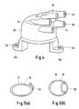
- the elastic seal member 18, shown in Figs. 5(a) and 5(b), is composed of an annular elastic seal member portion 81 which is interposed between the cover 17 and the base and an annular elastic seal member portion 82 which is interposed between the connector 51 and the cover 17.
- the seal member portions 81, 82 are each angularly formed in the same plane as shown in Fig. 5(b), and the smaller annular portion 82 is used around connector 51 to be perpendicular with respect to portion 81, as shown in Fig. 5(a).
- the seal member 19 is annularly shaped.
- the upper face of the base 2 is substantially flat with only a small annular step 2d.
- the insulation cover 17 surrounding the signal detection unit is provided with a circumferential wall which constitutes an internal lower half circumferential wall of the distributor.
- the upper half circumferential wall and part of the outer lower circumferential wall of the distributor are formed by the distributor cap 60.
- an H.T. electrical voltage distribution chamber is formed between the cover 17 and the distributor cap 60, and below this chamber is formed a signal detection unit chamber which is formed between the cover 17 and the housing 2.
- stepped portion 17a On the axial center portion of the cover 17 a stepped portion 17a is formed which constitutes a labyrinth passage between the circumferential portion of the collar 6 inserted thereinto. Thereby ozone and electrode powder due to electric discharge which are generated in the upper voltage distribution chamber are prevented from intruding into the lower signal detection unit 15 accommodating chamber.
- a side electrode 20 which is integrally molded with the distributor cap 60.
- a center electrode 21 is provided for transmitting the high voltage from an ignition coil (not shown) to electrodes 22 of a rotor 14 via a high voltage tower 83 and a high voltage tower 6c is provided for transmitting high voltage distributed to the side electrode 20 from the rotor electrode 22 to ignition spark plugs (not shown).
- the shaft 1 is supported on the base 2 via bearing 3.
- the rotatable plate 8 is sandwiched between the collars 6 and 4 and fixedly secured by the pin 5, and the rotatable plate 8 is inserted in the gap between the light emitting and receiving elements 23, 24 of the photoelectric type pickup 13 while inserting the collar 4 into the center aperture of the signal detection unit 15.
- the cover 17 is located so that the opening 72 of the cover 17 fits over the connector 51.
- a screw 9 is then inserted through the center of the collar 6 to secure the collar assembly to the shaft 1. Thereafter, the distributor rotor 14 is secured to the upper end of the collar 6.
- the annular elastic member 19 for sealing the distributor cap 60, the bush 6b of the attachment leg 16a of the cap being mated with the screw hole 2b of the base 2 and the screw 2c secures the cap 60 to the housing 2.
- the force exerted by the cap 60 pressing onto the housing is transmitted to the cover 17 via the elastic seal members 18 and 19 such that the cap 60 and the cover 17 are secured to the housing.
- a waterproof structure of the connector 51 is formed wherein the side wall cut-out 72 of the cover 17 presses the elastic seal member 18 around the connector 51, and further, the structure provides the cover 17 with the ventilation holes 71 communicating the inside of the distribution chamber to the outside thereof to facilitate discharge of gases, such as ozone generated at the rotor, thereby a stable ventilation performance and waterproof performance are obtained. Further, sufficient distance from the H.T. voltage distribution chamber to the surface of the base 2 at ground potential is maintained. Accordingly, the total height of the distributor is reduced, and the seal structure of the connector is simplified. As a result, the distributor is excellent in terms of light weight and reduction in production cost.
- the size of the opening 72 of the cover is formed much larger than the connector 51 and the side wall of the distributor cap 60 is now provided with a cut-out 61 for sealingly mating with the connector 51 via an annular elastic seal member 18.
- seal member 19 is eliminated so that a further reduction in the number of assembly parts is achieved.
- the construction is further simplified by providing a cover 17 with a continuous side wall, the cap 60 being located on the cover by the "O" ring seal 19, the cover being located on the base via an "0" ring seal 18a and the connector 51 passing through and being sealed to the base 2 by another "0" ring seal 18b.
- the signal detection unit accommodated inside the cover 17 is not limited to the crank angle sensor of the photoelectric pickup type described above and may be a magnetic pickup type or an ignition signal generation device.
- the circumferential wall of the inverted cup-shaped insulating cover which covers the flat base of the distributor forms a circumferential wall of the distributor, the number of metal parts of the distributor are reduced and the weight thereof is reduced and, as well, the diameter thereof is reduced so that a compact distributor is realized.
- base 2 which functions as the ground potential for the distributor is located far from the high voltage distribution portion so the axial length of the distributor may be shortened due to the interposition of the insulating cover.
Landscapes
- Engineering & Computer Science (AREA)
- Chemical & Material Sciences (AREA)
- Combustion & Propulsion (AREA)
- Mechanical Engineering (AREA)
- General Engineering & Computer Science (AREA)
- Ignition Installations For Internal Combustion Engines (AREA)
Description
- This invention relates to a distributor for high tension (H.T.) electrical voltage in an internal combustion engine.
- In a known distributor, an insulating resin cover is provided between a H.T. distributing portion connecting to spark plugs and a signal detection portion for producing signals in synchronism with engine rotation. A cap encompasses the distribution and signal detection portions and a connector extends through a circumferential side wall of a metallic cup-shaped base on which the cap locates. The connector connects the signal detector portion with, for example, an ignition advance angle mechanism. The base includes a ventilation hole and a drainage hole. So as to ensure a waterproof fit around the connector it is known to provide an elastic member on the side of the distributor and a plate fixed by screws so that the elastic member is pressed between the connector and the plate.
- DE-A-3109606 discloses an H.T. electrical voltage distribution device having a plastic supporting disc interposed between a plastic cap and a cup-shaped housing. Furthermore the connector of this reference is located between the housing and cap through the upper chamber of the H.T. electrical voltage distribution device so that reliability of the signal detection unit is degraded.
- With the above known distributor, a large number of parts are required, and complex and diversified manufacturing operations are required so that both material costs and assembly costs are expensive. Further, because the connector extends through an opening in the base side wall, the mating surface between the base and the cap is formed above the connector, therefore the height of the distributor is high for ensuring an adequate distance between the high voltage distributor portion and the earthing portion of the base.
- An object of the present invention is to reduce the size, the weight and the manufacturing cost of the distributor, in particular, to eliminate the metallic circumferential wall of the distributor base.
- According to this invention there is provided a distributor for a high tension electrical voltage in an internal combustion engine comprising a metal base supporting a cap, an engine crankshaft rotation signal detection means and an H.T. electrical voltage distribution means located within the cap, and a connector adapted to connect output signals from the signal detection means to outside said cap, characterised by the upper surface of the metal base being substantially flat, and by an inverted cup-shaped insulating cover located on the base adapted to provide a partition between the signal detection means and the distribution means.
- In one embodiment said cover has a cut-out to permit said connector therethrough.
- In one embodiment of the invention the cut-out closely conforms to the configuration of the connector so that the cover effectively forms a cover on the base surrounding the signal detection means and thereby forms a lower peripheral wall of the distributor. In such an embodiment the cover is sealed to the base by a sealing ring. In such an arrangement conveniently the ring is formed by a first annular portion which is positioned between the cover, the connector and the base, and a further annular portion which is orthogonal to the portion and which portion forms a seal between the cover and the connector. Preferably another seal is located between the cover and the cap.
- Advantageously, the base is substantially flat and the cap and the cover adjacent the base are substantially in the same plane.
- Advantageously, the cover is provided with an aperture extending from a side of said cover remote from said base and in a region locating said H.T. electrical voltage distribution means to externally of the cover.
- In an alternative embodiment, the cover has an enlarged cut-out about the connector and the cover is encompassed by the cap, the cap having a cut-out which is adapted to provide a seal about the connector.
- Advantageously, the first and further seal portions are integrally connected with one another.
- In a preferred embodiment the cover has a continuous side wall, a lower portion of the cover being sealed to the base via seal means, an upper portion of the cover being sealed to the cap via a further seal means, and the connector passes through an aperture in the base and is sealed therewith by another seal means.
- Thus, the present invention provides an inverted cup-shaped cover substantially inside a cap which cover provides insulating between a signal detection means and an H.T. electrical voltage distribution means, the cover in one embodiment closely sealing with an output connector of the signal detecting means, in another embodiment the cap closely sealing with the output connector, and in another embodiment providing a continuous seal with the base. By providing a base of the distributor which is substantially flat and a cover interposed between the base and the H.T. electrodes, the overall axial height of the distributor may be reduced without fear of an electrical leakage path being formed between the H.T. electrical voltage distribution means and the base which is at ground potential. By the use of sealing members, waterproof seals are obtained to prevent ingress of water to the distributor so that damage does not occur to the signal detection means. The cover also has the advantage of having a ventilation hole for the ozone produced at the H.T. electrical voltage distribution means.
- The invention will now be described, by way of example, with reference to the accompanying drawings in which:-
- Fig. 1 is a cross-sectional view of one embodiment of a distributor in accordance with this present invention,
- Fig. 2 is a perspective view in which the distributor cap and the insulator cover shown in Fig. 1 are removed,
- Fig. 3 is a perspective view of the insulating cover shown in Fig. 1,
- Fig. 4 is a perspective view of the distributor cap shown in Fig. 1,
- Fig. 5(a) is a view showing the seal in use, and
- Fig. 5(b) is a view showing the seal before use,
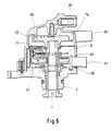
- Fig. 6 is a cross-sectional view showing another embodiment of the present invention, and
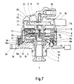
- Figure 7 shows a further embodiment of this invention.
- In the Figures, like reference numerals denote like parts.
- The distributor shown in Figs. 1 to 4 has a
base 2 supporting acap 60, and adistributor shaft 1, arranged to rotate in synchronism with an engine but at half the engine crankshaft revolution speed, is located through a hole in the base and supported by abearing 3 which is held in position on the base by aholder 3a. - At one end of the
distributor shaft 1 is secured a first collar 4 having a flange 4a, the flange 4a facing aflange 6a of asecond collar 6 and theflanges 4a, 6a being connected by apin 5 located in holes in the respective flanges. Between theflanges 4a and 6a is sandwiched an apertured rotatingplate 8, thesecond collar 6 and the first collar 4 being press-contacted to a stepped portion of theshaft 1. - A
case 10 made of a synthetic resin, circumferentially surrounds collar 4 and houses a hybrid integratedcircuit 12, alight receiving element 24, and aphotoelectric type pickup 13 including a holder provided with alight emitting element 23. Theelements apertured plate 8 for determining the engine crankshaft angle and output signals sent via aconnector 51 disposed through a gap in the cap side wall are provided for utilization by a control device. - The
shaft 1 is arranged to rotate in synchronism with the rotation of the engine (not shown), optical signals intermittently interrupted by the rotatingdisc 8 are converted into electrical signals by the integrated circuit, and crank angle position signals of the engine are transmitted from thesignal detection unit 15 via theconnector portion 51 to a control device (not shown) for controlling the engine. - The
case 10 is secured by a screw (not shown) to the bottom of the base. Hereinbelow, the assembly of the hybrid integratedcircuit 12 and thephotoelectric type pickup 13 is referred to asignal detection unit 15. - The
base 2 has aflange 2a in which ascrew hole 2b is formed and by inserting ascrew 2c into ametal bush 6b molded to anattachment leg 16a of thedistributor cap 60, so the distributor cap is secured to thebase 2. Between thebase 2 and thedistributor cap 60 is an inverted cup-shaped cover 17 made of polybutylenetelephthalate having anopening 72 for accommodating theconnector 51. The cover is sealed byelastic seal members base 2 and thecover 17, and between thecap 60 and thecover 17. Thecover 17 is provided with a pair ofventilation holes 71 communicating the interior of thedistributor cap 60 to the exterior thereof. Thecover 17 has a cut-out 72 to accommodate theconector 51 therethrough. - The
elastic seal member 18, shown in Figs. 5(a) and 5(b), is composed of an annular elasticseal member portion 81 which is interposed between thecover 17 and the base and an annular elasticseal member portion 82 which is interposed between theconnector 51 and thecover 17. Theseal member portions annular portion 82 is used aroundconnector 51 to be perpendicular with respect toportion 81, as shown in Fig. 5(a). Theseal member 19 is annularly shaped. - The upper face of the
base 2 is substantially flat with only a smallannular step 2d. In this respect, theinsulation cover 17 surrounding the signal detection unit is provided with a circumferential wall which constitutes an internal lower half circumferential wall of the distributor. The upper half circumferential wall and part of the outer lower circumferential wall of the distributor are formed by thedistributor cap 60. - In this embodiment, an H.T. electrical voltage distribution chamber is formed between the
cover 17 and thedistributor cap 60, and below this chamber is formed a signal detection unit chamber which is formed between thecover 17 and thehousing 2. - On the axial center portion of the
cover 17 a steppedportion 17a is formed which constitutes a labyrinth passage between the circumferential portion of thecollar 6 inserted thereinto. Thereby ozone and electrode powder due to electric discharge which are generated in the upper voltage distribution chamber are prevented from intruding into the lowersignal detection unit 15 accommodating chamber. - In the H.T. electrical voltage distribution chamber is a
side electrode 20 which is integrally molded with thedistributor cap 60. Acenter electrode 21 is provided for transmitting the high voltage from an ignition coil (not shown) toelectrodes 22 of arotor 14 via ahigh voltage tower 83 and ahigh voltage tower 6c is provided for transmitting high voltage distributed to theside electrode 20 from therotor electrode 22 to ignition spark plugs (not shown). - The method of assembly will now be described.
- The
shaft 1 is supported on thebase 2 viabearing 3. Around theconnector portion 51 of thesignal detection unit 15, is disposed the smallerannular portion 82 of theelastic seal member 18 and the largerannular portion 81 is disposed around the annular steppedportion 2d of thebase 2 and thereafter theunit 15 is fixed to thehousing 2 by a screw 14 (shown in Fig. 2). - The
rotatable plate 8 is sandwiched between thecollars 6 and 4 and fixedly secured by thepin 5, and therotatable plate 8 is inserted in the gap between the light emitting and receivingelements photoelectric type pickup 13 while inserting the collar 4 into the center aperture of thesignal detection unit 15. - Next, the
cover 17 is located so that theopening 72 of thecover 17 fits over theconnector 51. - A
screw 9 is then inserted through the center of thecollar 6 to secure the collar assembly to theshaft 1. Thereafter, thedistributor rotor 14 is secured to the upper end of thecollar 6. - On the outer circumferential stepped portion of the
cover 17 is disposed the annularelastic member 19 for sealing thedistributor cap 60, thebush 6b of theattachment leg 16a of the cap being mated with thescrew hole 2b of thebase 2 and thescrew 2c secures thecap 60 to thehousing 2. - The force exerted by the
cap 60 pressing onto the housing is transmitted to thecover 17 via theelastic seal members cap 60 and thecover 17 are secured to the housing. - A waterproof structure of the
connector 51 is formed wherein the side wall cut-out 72 of thecover 17 presses theelastic seal member 18 around theconnector 51, and further, the structure provides thecover 17 with the ventilation holes 71 communicating the inside of the distribution chamber to the outside thereof to facilitate discharge of gases, such as ozone generated at the rotor, thereby a stable ventilation performance and waterproof performance are obtained. Further, sufficient distance from the H.T. voltage distribution chamber to the surface of thebase 2 at ground potential is maintained. Accordingly, the total height of the distributor is reduced, and the seal structure of the connector is simplified. As a result, the distributor is excellent in terms of light weight and reduction in production cost. - In the alternative embodiment of Fig. 6, the size of the
opening 72 of the cover is formed much larger than theconnector 51 and the side wall of thedistributor cap 60 is now provided with a cut-out 61 for sealingly mating with theconnector 51 via an annularelastic seal member 18. In such anembodiment seal member 19 is eliminated so that a further reduction in the number of assembly parts is achieved. - In the further embodiment of Fig. 7, the construction is further simplified by providing a
cover 17 with a continuous side wall, thecap 60 being located on the cover by the "O"ring seal 19, the cover being located on the base via an "0"ring seal 18a and theconnector 51 passing through and being sealed to thebase 2 by another "0"ring seal 18b. - Also, in the alternative embodiment of Fig. 6, by providing a distributor cap which covers the entire circumference of the
cover 17, a double cover is formed so that water penetration is further prevented. - It is to be understood that the signal detection unit accommodated inside the
cover 17 is not limited to the crank angle sensor of the photoelectric pickup type described above and may be a magnetic pickup type or an ignition signal generation device. - In the present invention as explained above, since the circumferential wall of the inverted cup-shaped insulating cover which covers the flat base of the distributor forms a circumferential wall of the distributor, the number of metal parts of the distributor are reduced and the weight thereof is reduced and, as well, the diameter thereof is reduced so that a compact distributor is realized.
- Further, by the structure of the present invention,
base 2 which functions as the ground potential for the distributor is located far from the high voltage distribution portion so the axial length of the distributor may be shortened due to the interposition of the insulating cover. - It is to be understood that the invention has been described with reference to exemplary embodiments and modifications may be made without departing from the scope of the invention as defined in the appended claims.
Claims (10)
- A distributor for a high tension electrical voltage in an internal combustion engine comprising a metal base (2) supporting a cap (60), an engine crankshaft rotation signal detection means (15) and a high tension electrical voltage distribution means (20 - 22) located within the cap (60), and a connector (51) adapted to connect output signals from the signal detection means (15) to outside said cap (60), characterised by the upper surface of the metal base (2) being substantially flat, and by an inverted cup-shaped insulating cover (17) located on the base adapted to provide a partition between the signal detection means (15) and the distribution means (20 - 22).
- A distributor as claimed in claim 1 wherein said cover (17) has a cut-out (72) to permit said connector (51) therethrough.
- A distributor as claimed in claim 2 wherein the cut-out (72) closely conforms to the configuration of the connector (51) so that the cover (17) effectively forms a cover on the base (2) surrounding the signal detection means (15) and thereby forms a lower peripheral wall of the distributor.
- A distributor as claimed in claim 3 wherein the cover (17) is sealed to the base (2) by a sealing ring (18).
- A distributor as claimed in claim 4 wherein the ring (18) is formed by a first annular portion (81) which is positioned between the cover (17), the connector (51) and the base (2), and a further annular portion (82) which is orthogonal to the first portion (81) and which further portion (82) forms a seal between the cover (17) and the connector (51).
- A distributor as claimed in claim 5 wherein another seal (19) is located between the cover (17) and the cap (60).
- A distributor as claimed in claim 1 wherein the cover (17) has an enlarged cut-out (72) about the connector (51) and the cove (17) is encompassed by the cap (60), the cap (60) having a cut-out which is adapted to provide a seal about the connector (51).
- A distributor as claimed in claim 5 wherein the first and further seal portions (81, 82) are integrally connected with one another.
- A distributor as claimed in any preceding claim wherein the cover (17) is provided with an aperture (71) extending from a side of said cover remote from said base and in a region locating said high tension electrical voltage distribution means (20 - 22) to externally of the cover.
- A distributor as claimed in claim 1 wherein the cover (17) has a continuous side wall which is sealed to the base (2) by seal means (18a), an upper portion of the cover (17) being sealed to the cap by another seal means (19), and the connector (51) passes through an aperture in the base (2) and is sealed thereto by a further seal means (18b).
Applications Claiming Priority (2)
| Application Number | Priority Date | Filing Date | Title |
|---|---|---|---|
| JP1268949A JP2533654B2 (en) | 1989-10-18 | 1989-10-18 | Seal member used for internal combustion engine distributor |
| JP268949/89 | 1989-10-18 |
Publications (3)
| Publication Number | Publication Date |
|---|---|
| EP0424089A2 EP0424089A2 (en) | 1991-04-24 |
| EP0424089A3 EP0424089A3 (en) | 1991-05-29 |
| EP0424089B1 true EP0424089B1 (en) | 1994-11-30 |
Family
ID=17465532
Family Applications (1)
| Application Number | Title | Priority Date | Filing Date |
|---|---|---|---|
| EP90311318A Expired - Lifetime EP0424089B1 (en) | 1989-10-18 | 1990-10-16 | Internal combustion engine distributor |
Country Status (5)
| Country | Link |
|---|---|
| US (1) | US5090367A (en) |
| EP (1) | EP0424089B1 (en) |
| JP (1) | JP2533654B2 (en) |
| KR (1) | KR910008278A (en) |
| DE (1) | DE69014548T2 (en) |
Family Cites Families (13)
| Publication number | Priority date | Publication date | Assignee | Title |
|---|---|---|---|---|
| DE862979C (en) * | 1942-03-13 | 1953-01-15 | Bosch Gmbh Robert | Ignition distributor with dust protection device |
| US2619513A (en) * | 1949-06-30 | 1952-11-25 | Charles E Wolfenbarger | Sealed ignition unit |
| DE2536857C3 (en) * | 1975-08-19 | 1982-03-18 | Robert Bosch Gmbh, 7000 Stuttgart | Ignition distributors for internal combustion engines |
| DE7917194U1 (en) * | 1979-06-15 | 1980-11-27 | Robert Bosch Gmbh, 7000 Stuttgart | Ignition distributors for internal combustion engines |
| DE3109606A1 (en) * | 1981-03-13 | 1982-10-21 | Robert Bosch Gmbh, 7000 Stuttgart | Ignition distributor for internal-combustion engines |
| JPS5825580A (en) * | 1981-08-07 | 1983-02-15 | Nippon Denso Co Ltd | Ignition system with ignition coil integrating type ignition distributor |
| JPS58187578A (en) * | 1982-04-26 | 1983-11-01 | Nippon Denso Co Ltd | Distributor for ignition of internal-combustion engine |
| NZ210351A (en) * | 1984-11-27 | 1988-05-30 | Alfa Laval Nz Ltd | Milking machine pulsator control system using modular rate, ratio and timing delay units |
| US4661661A (en) * | 1985-10-01 | 1987-04-28 | Chrysler Motors Corporation | Spark shield and inlet air vent for an ignition distributor |
| JPS62180671U (en) * | 1986-05-07 | 1987-11-16 | ||
| JPS6371579A (en) * | 1986-09-16 | 1988-03-31 | Hitachi Ltd | Ventilator for ignition distributor |
| JPH0531267Y2 (en) * | 1987-11-09 | 1993-08-11 | ||
| JPH0663498B2 (en) * | 1988-09-19 | 1994-08-22 | 株式会社日立製作所 | Distributor for internal combustion engine |
-
1989
- 1989-10-18 JP JP1268949A patent/JP2533654B2/en not_active Expired - Fee Related
-
1990
- 1990-10-16 DE DE69014548T patent/DE69014548T2/en not_active Expired - Fee Related
- 1990-10-16 EP EP90311318A patent/EP0424089B1/en not_active Expired - Lifetime
- 1990-10-18 KR KR1019900016575A patent/KR910008278A/en not_active Application Discontinuation
- 1990-10-18 US US07/600,197 patent/US5090367A/en not_active Expired - Lifetime
Also Published As
| Publication number | Publication date |
|---|---|
| DE69014548D1 (en) | 1995-01-12 |
| KR910008278A (en) | 1991-05-31 |
| JPH03134267A (en) | 1991-06-07 |
| DE69014548T2 (en) | 1995-05-24 |
| JP2533654B2 (en) | 1996-09-11 |
| US5090367A (en) | 1992-02-25 |
| EP0424089A2 (en) | 1991-04-24 |
| EP0424089A3 (en) | 1991-05-29 |
Similar Documents
| Publication | Publication Date | Title |
|---|---|---|
| US5752852A (en) | Waterproof connector-mounting construction | |
| US4596973A (en) | Inductive transmitter | |
| EP0793319B1 (en) | Spark plug boot insulator | |
| CA2172585C (en) | Automotive ignition coil assembly | |
| JP2005327557A (en) | Power connection means for case | |
| US5139003A (en) | Distributor assembly for an internal combustion engine | |
| EP0424089B1 (en) | Internal combustion engine distributor | |
| US4907563A (en) | Housing of a distributor including an ignition coil for an internal combustion engine | |
| KR970011038B1 (en) | Distributor for internal combustion engine | |
| JPH0864306A (en) | Shield structure of direct mount shield connector for apparatus | |
| JP2830873B2 (en) | Power distribution | |
| JP2624892B2 (en) | Distributor for internal combustion engine | |
| US5351670A (en) | Ignition distributor for an internal combustion engine | |
| JPH08232821A (en) | Distributor | |
| JP2645475B2 (en) | Semiconductor type pressure detector | |
| JPH0447169A (en) | Distributor for internal combustion engine | |
| JP4370047B2 (en) | Ignition coil unit and spark plug unit with built-in pressure sensor using the same | |
| JP2512666Y2 (en) | Shield structure of ionized smoke detector | |
| JPH03264780A (en) | Closed type electric motor-driven compressor | |
| JP2581839B2 (en) | Engine power distribution | |
| JP4006633B2 (en) | Ignition device for internal combustion engine | |
| JPH10252628A (en) | Distributor | |
| JP2568233Y2 (en) | Distributor | |
| JP2002270281A (en) | Waterproof shielded connector | |
| JPH0252117B2 (en) |
Legal Events
| Date | Code | Title | Description |
|---|---|---|---|
| PUAI | Public reference made under article 153(3) epc to a published international application that has entered the european phase |
Free format text: ORIGINAL CODE: 0009012 |
|
| PUAL | Search report despatched |
Free format text: ORIGINAL CODE: 0009013 |
|
| 17P | Request for examination filed |
Effective date: 19901112 |
|
| AK | Designated contracting states |
Kind code of ref document: A2 Designated state(s): DE GB |
|
| AK | Designated contracting states |
Kind code of ref document: A3 Designated state(s): DE GB |
|
| 17Q | First examination report despatched |
Effective date: 19930623 |
|
| GRAA | (expected) grant |
Free format text: ORIGINAL CODE: 0009210 |
|
| AK | Designated contracting states |
Kind code of ref document: B1 Designated state(s): DE GB |
|
| REF | Corresponds to: |
Ref document number: 69014548 Country of ref document: DE Date of ref document: 19950112 |
|
| PLBE | No opposition filed within time limit |
Free format text: ORIGINAL CODE: 0009261 |
|
| STAA | Information on the status of an ep patent application or granted ep patent |
Free format text: STATUS: NO OPPOSITION FILED WITHIN TIME LIMIT |
|
| 26N | No opposition filed | ||
| REG | Reference to a national code |
Ref country code: GB Ref legal event code: IF02 |
|
| PGFP | Annual fee paid to national office [announced via postgrant information from national office to epo] |
Ref country code: GB Payment date: 20020926 Year of fee payment: 13 |
|
| PGFP | Annual fee paid to national office [announced via postgrant information from national office to epo] |
Ref country code: DE Payment date: 20021205 Year of fee payment: 13 |
|
| PG25 | Lapsed in a contracting state [announced via postgrant information from national office to epo] |
Ref country code: GB Free format text: LAPSE BECAUSE OF NON-PAYMENT OF DUE FEES Effective date: 20031016 |
|
| PG25 | Lapsed in a contracting state [announced via postgrant information from national office to epo] |
Ref country code: DE Free format text: LAPSE BECAUSE OF NON-PAYMENT OF DUE FEES Effective date: 20040501 |
|
| GBPC | Gb: european patent ceased through non-payment of renewal fee |
Effective date: 20031016 |