EP0422672A1 - Circuit de réduction du bruit d'un signal vidéo - Google Patents
Circuit de réduction du bruit d'un signal vidéo Download PDFInfo
- Publication number
- EP0422672A1 EP0422672A1 EP90119609A EP90119609A EP0422672A1 EP 0422672 A1 EP0422672 A1 EP 0422672A1 EP 90119609 A EP90119609 A EP 90119609A EP 90119609 A EP90119609 A EP 90119609A EP 0422672 A1 EP0422672 A1 EP 0422672A1
- Authority
- EP
- European Patent Office
- Prior art keywords
- video
- signal
- input
- noise reduction
- video signal
- Prior art date
- Legal status (The legal status is an assumption and is not a legal conclusion. Google has not performed a legal analysis and makes no representation as to the accuracy of the status listed.)
- Withdrawn
Links
Images

Classifications
-
- G—PHYSICS
- G11—INFORMATION STORAGE
- G11B—INFORMATION STORAGE BASED ON RELATIVE MOVEMENT BETWEEN RECORD CARRIER AND TRANSDUCER
- G11B20/00—Signal processing not specific to the method of recording or reproducing; Circuits therefor
- G11B20/24—Signal processing not specific to the method of recording or reproducing; Circuits therefor for reducing noise
-
- H—ELECTRICITY
- H04—ELECTRIC COMMUNICATION TECHNIQUE
- H04N—PICTORIAL COMMUNICATION, e.g. TELEVISION
- H04N5/00—Details of television systems
- H04N5/14—Picture signal circuitry for video frequency region
- H04N5/21—Circuitry for suppressing or minimising disturbance, e.g. moiré or halo
Definitions
- the present invention relates to a video signal noise reduction circuit for use in a video tape recorder (VTR) and the like, and, more particularly, to a video signal noise reduction circuit for reducing a noise component in video signals subjected to frame of field correlation, or in still picture signals.
- VTR video tape recorder
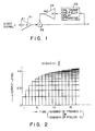
- FIG. 1 illustrates this digital filter.
- a video signal input is amplified by a first video amplifier 31 and supplied to one imput terminal of an adder 32.
- An output signal of the adder 32 is supplied as a video signal to another circuit.
- a part of the output signal is branched away and input to a one-frame or one-field delay apparatus 33.
- An output signal from the delay apparatus 33 is amplified by a second video amplifier 34 and fed back to the other input terminal of the adder 32.
- the magnitude of an output response signal will increase stepwise with time i.e., number of input frames or fields to reach the input signal level, as is shown in Fig. 2.
- the gain A1 of the first video amplifier 31 is (1 - K) and the gain A2 of the second video amplifier 34 is K, where K is cyclic coeffient (0 ⁇ K ⁇ 1).
- the energy No of the noise component included in the output signal is then expressed as where n (natural number) is a number of frames or fields of the video signal with the lapse of time, and N is energy of the noise component included in the input noise signal. It is well known that the energy No is down to (1 - K)/(1 + K) times.
- a noise reduction circuit for video signal which comprises: first video signal amplifying means of gain variable type for receiving the video signal; adding means for receiving an output signal from the first video signal amplifying means as one input signal thereof; one-picture delaying means for receiving a signal branched from an output signal of the adding means and outputting an output signal delayed by picture; second video signal amplifying means of gain variable type for receiving the delayed output signal from the one-picture delaying means and supplying an output signal to the adding means as the other imput signal thereof; and gain control means for controlling a gain of the first video signal amplifying means to A/n, and a gain of the second video signal amplifying means to (n - 1)A/n for every video picture input, corresponding to an output level A of the video signal and the number of n of the video pictures input from the input starting time of the video signal.
- the output signal level can be kept always at the predetermined level, and the ideal noise reduction can be performed. This is because all signal levels added at every input picture of the video pictures in the adder can be made equal.
- Fig. 3 is a block diagram showing an embodiment of a noise reduction circuit according to the present invention. This is a cyclic-type noise reduction circuit for reducing a noise component in the still picture signal or the video signal which is subjected to frame or field correlation in the VTR. As is shown in Fig.
- the noise reduction circuit comprises a first video amplifier 1 for amplifying an input video signal, an adder 2 to which an output signal of the first video amplifier 1 is input as one input signal thereof, a one-picture (one-frame or one-field) delay apparatus 3 to which a part of an output signal (output video signal) of the adder 2 is input, a second video amplifier 4 for amplifying the delayed video signal supplied from the one-picture delay apparatus 3 and for supplying an output signal to the other input terminal of the adder 2, and a gain control circuit 5.
- the first video amplifier 1 and the second video amplifier 4 are composed of a gain variable type amplifier each.
- the gain control circuit 5 adjusts a gain G1 of the first video amplifier 1 to A/n, and a gain G2 of the second video amplifier 4 to (n - 1)A/n, for every video picture input, i.e., every frame or field input of the video pictures, when an output level of the video signal is set to A (constant number), and an input frame or field number of the video pictures from the input starting time of the video signal is set to n .
- the gain G1 of the first video amplifier 1 is A
- N energy of the noise component included in the video picture input (N can be always kept constant).
- No energy of the noise component included in the output signal after the n-th video picture is input. (In the equation (3), intermediate calculations are omitted). Therefore, the energy No of the noise component which is included in the output signal at the time when number n ⁇ ⁇ is given as the above equation (1) in the prior art.
- the energy No of the noise component in the above embodiment according to the present invention can be expressed as:
- the present invention can provide a noise reduction circuit in which the output signal level can always be kept at a predetermined level, and the ideal noise reduction can be performed, since all signal levels which are added to every video picture input can be made equal. Further, neither omission of the information nor deterioration of the signal-to-noise ratio S/N occur even when number of frames or fields of the video signals is small.
Landscapes
- Engineering & Computer Science (AREA)
- Signal Processing (AREA)
- Multimedia (AREA)
- Picture Signal Circuits (AREA)
Applications Claiming Priority (2)
| Application Number | Priority Date | Filing Date | Title |
|---|---|---|---|
| JP263960/89 | 1989-10-12 | ||
| JP1263960A JPH03126380A (ja) | 1989-10-12 | 1989-10-12 | 映像雑音低減回路 |
Publications (1)
| Publication Number | Publication Date |
|---|---|
| EP0422672A1 true EP0422672A1 (fr) | 1991-04-17 |
Family
ID=17396633
Family Applications (1)
| Application Number | Title | Priority Date | Filing Date |
|---|---|---|---|
| EP90119609A Withdrawn EP0422672A1 (fr) | 1989-10-12 | 1990-10-12 | Circuit de réduction du bruit d'un signal vidéo |
Country Status (3)
| Country | Link |
|---|---|
| EP (1) | EP0422672A1 (fr) |
| JP (1) | JPH03126380A (fr) |
| KR (1) | KR910008709A (fr) |
Cited By (1)
| Publication number | Priority date | Publication date | Assignee | Title |
|---|---|---|---|---|
| EP0592196A2 (fr) * | 1992-10-08 | 1994-04-13 | Sony Corporation | Circuits d'élimination du bruit |
Citations (2)
| Publication number | Priority date | Publication date | Assignee | Title |
|---|---|---|---|---|
| US4064530A (en) * | 1976-11-10 | 1977-12-20 | Cbs Inc. | Noise reduction system for color television |
| GB2122050A (en) * | 1982-06-17 | 1984-01-04 | Philips Nv | X-ray image enhancement |
-
1989
- 1989-10-12 JP JP1263960A patent/JPH03126380A/ja active Pending
-
1990
- 1990-10-12 EP EP90119609A patent/EP0422672A1/fr not_active Withdrawn
- 1990-10-12 KR KR1019900016175A patent/KR910008709A/ko not_active IP Right Cessation
Patent Citations (2)
| Publication number | Priority date | Publication date | Assignee | Title |
|---|---|---|---|---|
| US4064530A (en) * | 1976-11-10 | 1977-12-20 | Cbs Inc. | Noise reduction system for color television |
| GB2122050A (en) * | 1982-06-17 | 1984-01-04 | Philips Nv | X-ray image enhancement |
Cited By (4)
| Publication number | Priority date | Publication date | Assignee | Title |
|---|---|---|---|---|
| EP0592196A2 (fr) * | 1992-10-08 | 1994-04-13 | Sony Corporation | Circuits d'élimination du bruit |
| US5404178A (en) * | 1992-10-08 | 1995-04-04 | Sony Corporation | Noise eliminating circuit |
| EP0592196A3 (en) * | 1992-10-08 | 1995-08-16 | Sony Corp | Noise eliminating circuits |
| KR100295562B1 (ko) * | 1992-10-08 | 2001-09-17 | 이데이 노부유끼 | 노이즈제거회로 |
Also Published As
| Publication number | Publication date |
|---|---|
| JPH03126380A (ja) | 1991-05-29 |
| KR910008709A (ko) | 1991-05-31 |
Similar Documents
| Publication | Publication Date | Title |
|---|---|---|
| EP0991270B1 (fr) | Appareil de traitement de signal vidéo pour l'amélioration du niveau du signal par contrôle automatique du gain et addition de trames | |
| US6593970B1 (en) | Imaging apparatus with dynamic range expanded, a video camera including the same, and a method of generating a dynamic range expanded video signal | |
| EP1457925A1 (fr) | Dispositif de traitement d'images, procédé de traitement d'images et logiciel de traitement d'images | |
| US5400083A (en) | Noise reduction apparatus for video signal | |
| US5185664A (en) | Method and apparatus for combining field and frame recursive noise reduction for video signals | |
| KR100297714B1 (ko) | 넓은동적범위를갖는영상장치및이의영상신호처리방법 | |
| US5930402A (en) | Method and device for local contrast enhancement of video signal | |
| US4833537A (en) | Noise reduction circuit for video signal having suitable nonlinear processing character | |
| KR950011820B1 (ko) | 디지탈 비데오 신호의 주파수 스펙트럼의 고주파수 부분을 피킹하는 장치 | |
| EP0422672A1 (fr) | Circuit de réduction du bruit d'un signal vidéo | |
| US4884140A (en) | Vignetting compensating circuit for a video camera | |
| US4000366A (en) | Adaptive gray scale control circuit for television video signals | |
| US4979043A (en) | Video signal processing circuit | |
| US4802010A (en) | Method and apparatus for generating an adaptive peaking signal increasing the sharpness of a video signal | |
| US4760449A (en) | Video signal processing apparatus | |
| JP2935389B2 (ja) | 映像信号処理装置及び非線形信号処理装置 | |
| JP2919722B2 (ja) | Ccd信号処理回路 | |
| JPH08256344A (ja) | 映像信号処理装置 | |
| JPH10173958A (ja) | 映像信号処理装置 | |
| JPH074003B2 (ja) | 信号圧縮装置 | |
| KR0178722B1 (ko) | 시시디카메라의 다이내믹 영역 확장방법 및 장치 | |
| JP2940264B2 (ja) | テレビジョン受像機 | |
| JP2545977B2 (ja) | 撮像装置における雑音抑圧方法 | |
| JP2578591B2 (ja) | 自動利得制御回路 | |
| JPH0369276A (ja) | ノイズ低減回路 |
Legal Events
| Date | Code | Title | Description |
|---|---|---|---|
| PUAI | Public reference made under article 153(3) epc to a published international application that has entered the european phase |
Free format text: ORIGINAL CODE: 0009012 |
|
| 17P | Request for examination filed |
Effective date: 19901012 |
|
| AK | Designated contracting states |
Kind code of ref document: A1 Designated state(s): DE FR GB |
|
| STAA | Information on the status of an ep patent application or granted ep patent |
Free format text: STATUS: THE APPLICATION HAS BEEN WITHDRAWN |
|
| 18W | Application withdrawn |
Withdrawal date: 19930215 |