EP0422196B1 - Procede et installation pour realiser un revetement sur les parois interieures d'un recipient metallurgique - Google Patents
Procede et installation pour realiser un revetement sur les parois interieures d'un recipient metallurgique Download PDFInfo
- Publication number
- EP0422196B1 EP0422196B1 EP90907161A EP90907161A EP0422196B1 EP 0422196 B1 EP0422196 B1 EP 0422196B1 EP 90907161 A EP90907161 A EP 90907161A EP 90907161 A EP90907161 A EP 90907161A EP 0422196 B1 EP0422196 B1 EP 0422196B1
- Authority
- EP
- European Patent Office
- Prior art keywords
- vessel
- mixture
- metallurgical vessel
- binder
- lining
- Prior art date
- Legal status (The legal status is an assumption and is not a legal conclusion. Google has not performed a legal analysis and makes no representation as to the accuracy of the status listed.)
- Expired - Lifetime
Links
Images


Classifications
-
- B—PERFORMING OPERATIONS; TRANSPORTING
- B22—CASTING; POWDER METALLURGY
- B22D—CASTING OF METALS; CASTING OF OTHER SUBSTANCES BY THE SAME PROCESSES OR DEVICES
- B22D41/00—Casting melt-holding vessels, e.g. ladles, tundishes, cups or the like
- B22D41/02—Linings
-
- B—PERFORMING OPERATIONS; TRANSPORTING
- B22—CASTING; POWDER METALLURGY
- B22D—CASTING OF METALS; CASTING OF OTHER SUBSTANCES BY THE SAME PROCESSES OR DEVICES
- B22D41/00—Casting melt-holding vessels, e.g. ladles, tundishes, cups or the like
- B22D41/02—Linings
- B22D41/023—Apparatus used for making or repairing linings
Definitions
- the present invention relates to a method for producing a coating on the interior walls of a metallurgical container intended to receive liquid metal.
- the present invention also relates to an installation for implementing the above method.
- patent application EP-A-0 289 480 on which the preambles of claims 1 and 9 are based.
- This patent application describes a device allowing the economic implementation of a process known as "guniting”. He therefore teaches projection under pressure, using a lance, of a pasty and curable aqueous mixture. Such a method makes it possible to project with a certain speed the particles already deposited and promotes the compactness and therefore the resistance of the coating thus obtained. It is however necessary to heat this coating to dry it.
- a template is placed inside a metallurgical container, a material composed of refractory particles and a thermosetting binder is pneumatically projected between the template and the interior walls of the container. leaving the template in place to cause the binder to harden, finally we remove the template.
- the sprayed material contains an inorganic compound containing water of crystallization.
- the material of the aforementioned type is compacted between the template and the interior walls of the container, either by tamping, or by vibration or impact.
- heating the material through the template represents a certain energy consumption and additional time to immobilize the metallurgical container.
- the object of the present invention is to remedy the drawbacks of known methods and to propose a method which is simple, rapid and economical to use, and which is particularly well suited to producing the wear coating of a metallurgical container.
- the object of the present invention is also to propose an installation for the implementation of said method.
- the newly spread material forms with the material deposited previously a monolithic coating which adheres to the wall on which it is spread.
- the installation of the coating can therefore be carried out very quickly, without the aid of a template, and without the need for compaction of the material.
- the material deposited being substantially dry, no drying is necessary, and, when the quality of the cast steel does not require the departure of the water of crystallization and / or certain gases which the coating may contain, the metallurgical container is therefore practically immediately returned to the operating circuit, which allows a very rapid rotation rate thereof.
- the method makes it possible to deposit a layer of determined thickness: if a consumable layer is deposited on a partially worn permanent coating, it is possible to follow the external surface thereof and to avoid any unnecessary excess of material.
- the coating obtained is refractory insulator.
- this installation makes it possible, in most cases, without a template, to coat a coating which does not require any drying before putting the container back into service, and the newly spread material forms with the material already in place a monolithic block. which adheres to the wall.
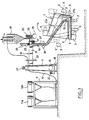
- the installation according to the invention is suitable for coating the interior walls of a ladle 1 whose casing 2, provided with ears 3, is internally lined with a coating permanent refractory 4, made of shaped bricks or refractory concrete.
- This permanent refractory coating 4 must be covered with a wear coating 5 deposited on the bottom and the inner side walls of the ladle 1 and intended to be in contact with the liquid metal.
- the ladle 1 is placed on a tilting support (not shown) known per se.
- This support tilting can receive the pocket 1 in the position shown in dashes in the figure, in which the bottom of the pocket 1 is substantially horizontal.
- the support can also tilt the pocket 1 into the position shown in solid lines, in which the lowest part of the interior wall of the pocket is substantially horizontal and turned upwards.
- the tilting support comprises means, known in themselves and shown diagrammatically by rollers 6, 7, 8, for rotating the pocket 1 around its axis X, X ', in this tilted position, as shown diagrammatically by the arrows 9.
- the installation comprises means for preparing or receiving and conveying a substantially dry material intended to be spread to form the wear coating 5.
- these means consist of two hoppers 10a, 10b, mounted on a frame 11 and adapted to receive, in bags (not shown) or by a conveyor, for example a conveyor belt (not shown ), the substantially dry mixture to be deposited.
- these hoppers 10a, 10b can be alternately closed and pressurized with compressed air for the pneumatic transport of the material by a flexible pipe 12 to a cyclonic separator 13 which separates the material to be deposited from the air of transport.
- the material can thus be conveyed without pressure by simple gravity in a flexible pipe 14 to the discharge point 15 which can be provided with a valve (not shown).
- the cyclonic separator 13 and the flexible pipe 14 are carried by a robot 16.
- the robot 16 has a substantially vertical barrel 17, which can rotate around its axis by relative to a fixed base 18 and driven in rotation in one direction or the other, as indicated by arrow 19, by a motor 20.
- a substantially horizontal arm 21 carried by the barrel 17 can move vertically (arrow 22) along the barrel 17 under the action of a motor 23.
- the cyclonic separator 13 is carried by the arm 21.
- a second substantially horizontal arm 24 is articulated at one of its ends at the end of the arm 21 and can pivot in a horizontal plane around the end of the arm 21 (arrow 25) under the action of a motor 26.
- the other end of the arm 24 supports a substantially vertical mast 27 which can move vertically (arrow 28) under the action of a first motor 29, and which can rotate around its axis (arrow 30) under the action of 'a second motor 31.
- the mast 27 is extended downwards by a part 27a which extends obliquely and which ends in a substantially vertical part 27b.
- the flexible pipe 14 is hung along the mast 27, the discharge point 15 of this pipe being adjacent to the lower end of the part 27b of the mast 27.
- the diameter of this flexible pipe 14 is sufficient to allow satisfactory flow of the material by gravity without risk of clogging.
- the robot 16 also includes means, not shown, for coordinating the arrival of the material, the movements of the elements which compose it and the movements of the pocket on the tilting support.
- the installation according to the invention comprises a tilting support 32 capable of pivoting about an axis 33 relative to a fixed frame 34 under the action of a pivoting cylinder 35.
- the tilting support 32 carries a turntable 36 capable of rotating relative to the support 32 under the action of a motor 37 by any known means symbolized by balls 38.
- the turntable 36 is intended to receive a pocket casting 1 fixed on the turntable 36 by means of clamps 39 actuated by a jack 40, so as to rotate the pocket 1 around its axis X, X '(arrow 41).
- the lowest part of the interior wall of the pocket 1 is substantially horizontal.
- the material to be spread is stored in a hopper 42, which has for example a conical shape, inside which rotates a mixing screw 43 driven by a motor not shown. At the lower part of the hopper 42, the material falls into a conveyor screw 44 at the discharge end 45 from which the material is deposited on the inside wall of the bag 1.
- the screw 44 is shown mounted on a jack 46 which allows it to be fitted onto the lower part of the hopper 42 and to separate it from the latter, this lower part of the hopper then being closed by a valve not shown.
- the hopper 42 and the conveyor screw 44 are mounted on a carriage 47 movable along the arrow 47a in the axial direction of the screw 44 to allow the material to be spread along a generator of the interior wall of the pocket 1.
- the carriage 47 is itself mounted on a chassis 48 which is for example movable in the direction perpendicular to the direction of movement of the carriage 47.
- the assembly forms a robot 49 equipped with means not shown to coordinate the arrival of the material with the movements from pocket 1 and those of the carriage 47.
- the bottom 4a of the pocket can be coated in a similar manner to that described with reference to FIG. 1, this bottom being in a horizontal position and the coating material being poured onto this bottom, for example by means a tubular chute movable over the entire surface of said bottom.
- a continuous casting distributor 50 is mounted on a tilting frame 51 of any known type near, for example, the robot 16 with articulated arms described above in reference to figure 1.
- the distributor 50 is shown in Figure 3 in the inverted position which allows to drop the wear coating used and "wolves" of metal and / or slag attached to it, for example in a waste bin not represented.
- the distributor 50 is shown in Figure 4A in the normal position of use; the horizontal arms 21 and 24 are deployed and the mast 27 is oriented so as to allow the coating to be formed on the bottom 52 of the distributor 50.
- the flexible pipe 14 is not shown for the sake of clarity of the drawing.
- the distributor 50 is shown in Figure 4B in the tilted position to the left of the figure, in which the longitudinal side wall 53 is substantially in a horizontal position: the bent portion 27a can thus penetrate inside the distributor to spread the material over the entire surface of the wall 53 and thus form the covering 55.
- the distributor 50 is tilted to the right and the articulated arm 24 is deployed so as to allow the deposition of the material on the wall 54 and the formation of the coating 55.
- the material constituting the coating wear 5, 55 is a substantially dry material comprising a mixture of refractory particles and a binder of the thermosetting type or equivalent, the composition and the particle size of the mixture of refractory particles being such that this mixture sintered in contact with the liquid metal.
- this material is intended to be spread over the interior walls of a metallurgical container which are initially at a temperature sufficient to be able to heat the material deposited thereon to a temperature allowing the softening and setting of the binder of the thermosetting type. or equivalent and the formation of a monolithic coating which adheres to these interior walls of the container 1, 50.
- Refractory particles can be chosen, for example, from the group comprising magnesian, silico-magnesian, silico-aluminous, aluminous, siliceous particles, calcium carbonate, lime, dolomite, carbon, chromium oxide, zircon, and mixtures thereof. These particles can be in the form of grains, powders and / or fibers.
- thermosetting type or equivalent for example, from the group comprising natural and synthetic thermosetting resins such as for example phenol-formaldehyde resins, urea-formaldehyde resins, polyvinyl resins, etc., mineral binders of the thermosetting type or equivalent softening with heat such as for example sodium silicate (which dissolves around 70 ° C), metasilicate, etc., organic binders and / or agglutinants such as for example starch, starch, stearate , carboxymethylcellulose, etc., and mixtures of these compounds.
- natural and synthetic thermosetting resins such as for example phenol-formaldehyde resins, urea-formaldehyde resins, polyvinyl resins, etc.
- mineral binders of the thermosetting type or equivalent softening with heat such as for example sodium silicate (which dissolves around 70 ° C), metasilicate, etc.
- organic binders and / or agglutinants such as for example
- the refractory particles can be simply mixed with particles of the binder of the thermosetting type.
- the particles refractories can be embedded in the binder, for example if very hygroscopic particles such as dolomite particles are used which tend to absorb moisture.
- the widespread mixture is preferably refractory insulator, and is made up of particles whose particle size is studied so as to give the coating in place after sintering in contact with the liquid metal a total porosity greater than 45%: this insulating nature of the coating limits cooling.
- liquid metal in contact with the walls of the metallurgical container which makes it possible to dispense with preheating the walls of the container before use without risk of solidification of metal in contact with them.
- the widespread mixture can have a general composition of the following type: Refractory particles in grains and / or powders: 80 to 100% Organic and / or mineral fibers: 0 to 10% Binder: 0 to 10%
- compositions of mixtures of different characters can thus be given as nonlimiting examples, in which the binder appears in the section "loss on ignition”:
- the permanent internal coating can thus be at a temperature ranging from approximately 250 ° C. to approximately 400 ° C.: it is thus possible to refill a container shortly after its use.
- a container whose walls are cold is to be refilled, one begins by reheating them to the required temperature with any known means, for example a gas burner or an infrared ramp.
- Some walls may not be accessible by the means described above and are coated in any known manner, automatically or manually.
- the pouring orifice of the container is temporarily closed during the deposition of the coating.
- the binder softens and becomes sticky, which makes it possible to stick the material to the interior walls and to form on them a monolithic coating with the material already in square. It is thus possible to quickly move the container and even to tilt it nearly 180 ° to coat a wall opposite to that already coated without the risk of dropping the coating already in place.
- the means used for storing, transporting and spreading the coating material may be different from those described: it is for example possible to use, instead of the hoppers 10 alternately pressurized, a barrel type spraying machine suitable for conveying pulverulent materials which may contain fibers, and more generally any set of known means of transport and handling capable of conveying the material to be spread over the entire wall or part of the interior wall to be coated. Any device making it possible to separate the material to be spread from the compressed transport air can be used in place of the cyclonic separator 13.
Landscapes
- Engineering & Computer Science (AREA)
- Mechanical Engineering (AREA)
- Furnace Housings, Linings, Walls, And Ceilings (AREA)
- Other Surface Treatments For Metallic Materials (AREA)
- Details Of Rigid Or Semi-Rigid Containers (AREA)
- Casting Support Devices, Ladles, And Melt Control Thereby (AREA)
Priority Applications (1)
| Application Number | Priority Date | Filing Date | Title |
|---|---|---|---|
| AT90907161T ATE100364T1 (de) | 1989-04-26 | 1990-04-25 | Verfahren und vorrichtung zur herstellung einer auskleidung auf den innenflaechen eines metallurgischen gefaesses. |
Applications Claiming Priority (2)
| Application Number | Priority Date | Filing Date | Title |
|---|---|---|---|
| FR8905528A FR2646367B1 (fr) | 1989-04-26 | 1989-04-26 | Procede et installation pour realiser un revetement sur les parois interieures d'un recipient metallurgique |
| FR8905528 | 1989-04-26 |
Publications (2)
| Publication Number | Publication Date |
|---|---|
| EP0422196A1 EP0422196A1 (fr) | 1991-04-17 |
| EP0422196B1 true EP0422196B1 (fr) | 1994-01-19 |
Family
ID=9381146
Family Applications (1)
| Application Number | Title | Priority Date | Filing Date |
|---|---|---|---|
| EP90907161A Expired - Lifetime EP0422196B1 (fr) | 1989-04-26 | 1990-04-25 | Procede et installation pour realiser un revetement sur les parois interieures d'un recipient metallurgique |
Country Status (12)
| Country | Link |
|---|---|
| US (1) | US5160692A (cs) |
| EP (1) | EP0422196B1 (cs) |
| KR (1) | KR940003901B1 (cs) |
| AU (1) | AU627585B2 (cs) |
| BR (1) | BR9006724A (cs) |
| CA (1) | CA2030787A1 (cs) |
| CS (1) | CS203890A3 (cs) |
| DE (1) | DE69006158T2 (cs) |
| ES (1) | ES2048492T3 (cs) |
| FR (1) | FR2646367B1 (cs) |
| HU (1) | HUT56750A (cs) |
| WO (1) | WO1990012666A1 (cs) |
Families Citing this family (11)
| Publication number | Priority date | Publication date | Assignee | Title |
|---|---|---|---|---|
| AT399464B (de) * | 1992-03-05 | 1995-05-26 | Veitsch Radex Ag | Vorrichtung zur aufbereitung und zuführung einer monolithischen keramischen masse in ein metallurgisches schmelzgefäss |
| WO1995016795A1 (en) * | 1993-12-13 | 1995-06-22 | Minteq International Inc. | Furnace spraying repair device |
| FR2728185A1 (fr) | 1994-12-19 | 1996-06-21 | Daussan & Co | Procede pour appliquer sur les faces interieures d'un recipient metallurgique un revetement de protection comportant au moins deux couches |
| FR2732915B1 (fr) * | 1995-04-14 | 1997-06-13 | Daussan & Co | Procede pour appliquer a l'interieur d'un recipient metallurgique un revetement de protection comportant au moins deux couches |
| US5885510A (en) * | 1997-02-07 | 1999-03-23 | Alcoa Chemie Gmbh | Methods of making refractory bodies |
| US6165926A (en) * | 1998-06-24 | 2000-12-26 | Alcoa Chemie Gmbh | Castable refractory composition and methods of making refractory bodies |
| US6268018B1 (en) * | 1999-02-09 | 2001-07-31 | Harbison-Walker Refractories Company | Method of applying a non-slumping pumpable castable high purity silica composition |
| KR100484539B1 (ko) * | 2002-08-01 | 2005-05-17 | 주식회사 포스렉 | 슬래그 포트용 도포제 |
| CN100453211C (zh) * | 2007-06-22 | 2009-01-21 | 河北理工大学 | 一种中间包干式工作衬的制备方法 |
| CN101858694B (zh) * | 2010-06-22 | 2011-11-16 | 武汉科技大学 | 一种用于感应炉预制炉衬的成型模具 |
| KR101526440B1 (ko) * | 2013-11-08 | 2015-06-05 | 주식회사 포스코 | 저장용기 및 저장용기 제조방법 |
Family Cites Families (6)
| Publication number | Priority date | Publication date | Assignee | Title |
|---|---|---|---|---|
| US3637412A (en) * | 1968-09-16 | 1972-01-25 | Combustion Eng | Ladle lining refractory |
| CA1016962A (en) * | 1973-01-04 | 1977-09-06 | Crawford B. Murton | Applying a refractory lining on hot metallurgical containments |
| FR2533492B1 (fr) * | 1982-09-29 | 1986-06-13 | Gilson Jacques | Procede et installation de moulage d'un revetement refractaire de conteneur pour metal liquide |
| US4696455A (en) * | 1984-10-30 | 1987-09-29 | Consolidated Ceramic Products, Inc. | Zircon and MgO preheatable insulating refractory liners and methods of use thereof |
| FR2585273B1 (fr) * | 1985-07-24 | 1988-05-13 | Daussan & Co | Revetement pour proteger l'interieur d'un recipient metallurgique et procede pour realiser ce revetement |
| BE1000516A6 (fr) * | 1987-04-30 | 1989-01-10 | Centre Rech Metallurgique | Dispositif pour deposer un revetement protecteur sur la paroi interieure d'un recipient metallurgique. |
-
1989
- 1989-04-26 FR FR8905528A patent/FR2646367B1/fr not_active Expired - Fee Related
-
1990
- 1990-04-24 CS CS902038A patent/CS203890A3/cs unknown
- 1990-04-25 DE DE90907161T patent/DE69006158T2/de not_active Expired - Fee Related
- 1990-04-25 WO PCT/FR1990/000297 patent/WO1990012666A1/fr not_active Ceased
- 1990-04-25 AU AU56576/90A patent/AU627585B2/en not_active Ceased
- 1990-04-25 BR BR909006724A patent/BR9006724A/pt unknown
- 1990-04-25 KR KR1019900702675A patent/KR940003901B1/ko not_active Expired - Fee Related
- 1990-04-25 HU HU904258A patent/HUT56750A/hu unknown
- 1990-04-25 US US07/623,907 patent/US5160692A/en not_active Expired - Fee Related
- 1990-04-25 ES ES90907161T patent/ES2048492T3/es not_active Expired - Lifetime
- 1990-04-25 CA CA002030787A patent/CA2030787A1/en not_active Abandoned
- 1990-04-25 EP EP90907161A patent/EP0422196B1/fr not_active Expired - Lifetime
Also Published As
| Publication number | Publication date |
|---|---|
| KR920700082A (ko) | 1992-02-19 |
| FR2646367B1 (fr) | 1994-04-01 |
| US5160692A (en) | 1992-11-03 |
| EP0422196A1 (fr) | 1991-04-17 |
| FR2646367A1 (fr) | 1990-11-02 |
| AU5657690A (en) | 1990-11-16 |
| HU904258D0 (en) | 1991-07-29 |
| DE69006158T2 (de) | 1994-05-05 |
| WO1990012666A1 (fr) | 1990-11-01 |
| DE69006158D1 (de) | 1994-03-03 |
| CA2030787A1 (en) | 1990-10-27 |
| AU627585B2 (en) | 1992-08-27 |
| HUT56750A (en) | 1991-10-28 |
| CS203890A3 (en) | 1992-11-18 |
| ES2048492T3 (es) | 1994-03-16 |
| KR940003901B1 (ko) | 1994-05-09 |
| BR9006724A (pt) | 1991-08-06 |
Similar Documents
| Publication | Publication Date | Title |
|---|---|---|
| EP0214882B2 (fr) | Revêtement pour protéger l'intérieur d'un récipient métallurgique et procédé pour réaliser ce revêtement | |
| EP0086923B1 (fr) | Forme, procédé et composition pour le moulage par soufflage du revêtement réfractaire consommable d'un récipient destiné à contenir du métal en fusion | |
| EP0422196A1 (fr) | Procede et installation pour realiser un revetement sur les parois interieures d'un recipient metallurgique. | |
| GB2109099A (en) | Composite refractory articles and method of manufacturing them | |
| WO1992020479A1 (fr) | Procede pour appliquer sur les faces interieures d'un recipient metallurgique un revetement de protection comportant au moins deux couches, et revetement de protection ainsi obtenu | |
| GB2154228A (en) | Composition of matter for use in forming refractory masses in situ | |
| FR2611151A1 (fr) | Dispositif de prechauffage et/ou d'obturation et de debouchage d'un orifice de coulee et procede pour sa mise en oeuvre | |
| US4330107A (en) | Teapot ladle and method of use | |
| JPH09316819A (ja) | 舗道における新旧舗装境界ラインのジョイントシール機 | |
| WO1992000157A1 (fr) | Procede pour appliquer sur les faces interieures d'un recipient metallurgique un revetement de protection comportant au moins deux couches, et revetement de protection ainsi obtenu | |
| BE820783A (fr) | Procede pour appliquer un garnissage refractaire dans des recipients metallurgiques | |
| US5511762A (en) | Consumable form with degradable lining | |
| CN110257586B (zh) | 渣斗和渣斗的加工方法 | |
| FR2533847A1 (fr) | Procede et installation de manutention de moules de fonderie pour la coulee sous basse pression d'alliages metalliques tres oxydables | |
| JP2690500B2 (ja) | 耐火物ブロックの装着方法 | |
| LU81761A1 (fr) | Procede de revetement de la paroi interne d'un four ou appareil analogue | |
| JPH0245111B2 (cs) | ||
| KR900009216B1 (ko) | 야금용 용기 내부 보호 라이닝 및 그 성형방법 | |
| KR100840267B1 (ko) | 고로 보수 방법 | |
| JP4279392B2 (ja) | 溶融金属鋳造用タンディッシュの羽口周りの熱間補修方法及びそれに用いる熱間補修用容器 | |
| JPH0339782B2 (cs) | ||
| BE835396Q (fr) | Perfectionnements apportes aux repartiteurs garnis de refractaire | |
| JPH0356825B2 (cs) | ||
| JP2587827Y2 (ja) | 転炉出鋼口用栓 | |
| EP2841221A1 (fr) | Procede d'obtention d'une piece metallique a partir d'un modele perdu |
Legal Events
| Date | Code | Title | Description |
|---|---|---|---|
| PUAI | Public reference made under article 153(3) epc to a published international application that has entered the european phase |
Free format text: ORIGINAL CODE: 0009012 |
|
| 17P | Request for examination filed |
Effective date: 19901211 |
|
| AK | Designated contracting states |
Kind code of ref document: A1 Designated state(s): AT BE CH DE DK ES GB IT LI LU NL SE |
|
| 17Q | First examination report despatched |
Effective date: 19920806 |
|
| GRAA | (expected) grant |
Free format text: ORIGINAL CODE: 0009210 |
|
| AK | Designated contracting states |
Kind code of ref document: B1 Designated state(s): AT BE CH DE DK ES GB IT LI LU NL SE |
|
| PG25 | Lapsed in a contracting state [announced via postgrant information from national office to epo] |
Ref country code: DK Effective date: 19940119 |
|
| REF | Corresponds to: |
Ref document number: 100364 Country of ref document: AT Date of ref document: 19940215 Kind code of ref document: T |
|
| ITF | It: translation for a ep patent filed | ||
| GBT | Gb: translation of ep patent filed (gb section 77(6)(a)/1977) |
Effective date: 19940124 |
|
| REF | Corresponds to: |
Ref document number: 69006158 Country of ref document: DE Date of ref document: 19940303 |
|
| REG | Reference to a national code |
Ref country code: ES Ref legal event code: FG2A Ref document number: 2048492 Country of ref document: ES Kind code of ref document: T3 |
|
| EPTA | Lu: last paid annual fee | ||
| PLBE | No opposition filed within time limit |
Free format text: ORIGINAL CODE: 0009261 |
|
| STAA | Information on the status of an ep patent application or granted ep patent |
Free format text: STATUS: NO OPPOSITION FILED WITHIN TIME LIMIT |
|
| 26N | No opposition filed | ||
| EAL | Se: european patent in force in sweden |
Ref document number: 90907161.5 |
|
| PGFP | Annual fee paid to national office [announced via postgrant information from national office to epo] |
Ref country code: SE Payment date: 19960401 Year of fee payment: 7 Ref country code: LU Payment date: 19960401 Year of fee payment: 7 |
|
| PGFP | Annual fee paid to national office [announced via postgrant information from national office to epo] |
Ref country code: GB Payment date: 19960411 Year of fee payment: 7 |
|
| PGFP | Annual fee paid to national office [announced via postgrant information from national office to epo] |
Ref country code: AT Payment date: 19960416 Year of fee payment: 7 |
|
| PGFP | Annual fee paid to national office [announced via postgrant information from national office to epo] |
Ref country code: ES Payment date: 19960424 Year of fee payment: 7 |
|
| PGFP | Annual fee paid to national office [announced via postgrant information from national office to epo] |
Ref country code: NL Payment date: 19960430 Year of fee payment: 7 |
|
| PGFP | Annual fee paid to national office [announced via postgrant information from national office to epo] |
Ref country code: CH Payment date: 19960502 Year of fee payment: 7 Ref country code: BE Payment date: 19960502 Year of fee payment: 7 |
|
| PGFP | Annual fee paid to national office [announced via postgrant information from national office to epo] |
Ref country code: DE Payment date: 19960626 Year of fee payment: 7 |
|
| PG25 | Lapsed in a contracting state [announced via postgrant information from national office to epo] |
Ref country code: LU Free format text: LAPSE BECAUSE OF NON-PAYMENT OF DUE FEES Effective date: 19970425 Ref country code: GB Effective date: 19970425 Ref country code: AT Effective date: 19970425 |
|
| PG25 | Lapsed in a contracting state [announced via postgrant information from national office to epo] |
Ref country code: SE Effective date: 19970426 Ref country code: ES Free format text: LAPSE BECAUSE OF NON-PAYMENT OF DUE FEES Effective date: 19970426 |
|
| PG25 | Lapsed in a contracting state [announced via postgrant information from national office to epo] |
Ref country code: LI Free format text: LAPSE BECAUSE OF NON-PAYMENT OF DUE FEES Effective date: 19970430 Ref country code: CH Free format text: LAPSE BECAUSE OF NON-PAYMENT OF DUE FEES Effective date: 19970430 Ref country code: BE Effective date: 19970430 |
|
| BERE | Be: lapsed |
Owner name: DAUSSAN ET CIE Effective date: 19970430 |
|
| PG25 | Lapsed in a contracting state [announced via postgrant information from national office to epo] |
Ref country code: NL Effective date: 19971101 |
|
| REG | Reference to a national code |
Ref country code: CH Ref legal event code: PL |
|
| GBPC | Gb: european patent ceased through non-payment of renewal fee |
Effective date: 19970425 |
|
| PG25 | Lapsed in a contracting state [announced via postgrant information from national office to epo] |
Ref country code: DE Free format text: LAPSE BECAUSE OF NON-PAYMENT OF DUE FEES Effective date: 19980101 |
|
| NLV4 | Nl: lapsed or anulled due to non-payment of the annual fee |
Effective date: 19971101 |
|
| EUG | Se: european patent has lapsed |
Ref document number: 90907161.5 |
|
| REG | Reference to a national code |
Ref country code: ES Ref legal event code: FD2A Effective date: 19990405 |
|
| PG25 | Lapsed in a contracting state [announced via postgrant information from national office to epo] |
Ref country code: IT Free format text: LAPSE BECAUSE OF NON-PAYMENT OF DUE FEES Effective date: 20050425 |