EP0422169B1 - Optisches system zur abbildung des lichts von lichtquellen - Google Patents
Optisches system zur abbildung des lichts von lichtquellen Download PDFInfo
- Publication number
- EP0422169B1 EP0422169B1 EP90906118A EP90906118A EP0422169B1 EP 0422169 B1 EP0422169 B1 EP 0422169B1 EP 90906118 A EP90906118 A EP 90906118A EP 90906118 A EP90906118 A EP 90906118A EP 0422169 B1 EP0422169 B1 EP 0422169B1
- Authority
- EP
- European Patent Office
- Prior art keywords
- light
- optical system
- focal length
- astigmatic
- lens
- Prior art date
- Legal status (The legal status is an assumption and is not a legal conclusion. Google has not performed a legal analysis and makes no representation as to the accuracy of the status listed.)
- Expired - Lifetime
Links
- 230000003287 optical effect Effects 0.000 title claims abstract description 22
- 238000003384 imaging method Methods 0.000 title abstract description 5
- 230000000694 effects Effects 0.000 claims abstract description 11
- 201000009310 astigmatism Diseases 0.000 claims description 15
- 230000006835 compression Effects 0.000 claims 2
- 238000007906 compression Methods 0.000 claims 2
- 230000032683 aging Effects 0.000 abstract description 2
- 238000004519 manufacturing process Methods 0.000 description 5
- 230000005855 radiation Effects 0.000 description 3
- 239000006059 cover glass Substances 0.000 description 2
- 239000000463 material Substances 0.000 description 2
- 238000007493 shaping process Methods 0.000 description 2
- 238000006073 displacement reaction Methods 0.000 description 1
Images

Classifications
-
- G—PHYSICS
- G02—OPTICS
- G02B—OPTICAL ELEMENTS, SYSTEMS OR APPARATUS
- G02B6/00—Light guides; Structural details of arrangements comprising light guides and other optical elements, e.g. couplings
- G02B6/24—Coupling light guides
- G02B6/42—Coupling light guides with opto-electronic elements
- G02B6/4201—Packages, e.g. shape, construction, internal or external details
- G02B6/4204—Packages, e.g. shape, construction, internal or external details the coupling comprising intermediate optical elements, e.g. lenses, holograms
- G02B6/4206—Optical features
-
- G—PHYSICS
- G02—OPTICS
- G02B—OPTICAL ELEMENTS, SYSTEMS OR APPARATUS
- G02B13/00—Optical objectives specially designed for the purposes specified below
-
- G—PHYSICS
- G02—OPTICS
- G02B—OPTICAL ELEMENTS, SYSTEMS OR APPARATUS
- G02B19/00—Condensers, e.g. light collectors or similar non-imaging optics
- G02B19/0004—Condensers, e.g. light collectors or similar non-imaging optics characterised by the optical means employed
- G02B19/0009—Condensers, e.g. light collectors or similar non-imaging optics characterised by the optical means employed having refractive surfaces only
- G02B19/0014—Condensers, e.g. light collectors or similar non-imaging optics characterised by the optical means employed having refractive surfaces only at least one surface having optical power
-
- G—PHYSICS
- G02—OPTICS
- G02B—OPTICAL ELEMENTS, SYSTEMS OR APPARATUS
- G02B19/00—Condensers, e.g. light collectors or similar non-imaging optics
- G02B19/0033—Condensers, e.g. light collectors or similar non-imaging optics characterised by the use
- G02B19/0047—Condensers, e.g. light collectors or similar non-imaging optics characterised by the use for use with a light source
- G02B19/0052—Condensers, e.g. light collectors or similar non-imaging optics characterised by the use for use with a light source the light source comprising a laser diode
-
- G—PHYSICS
- G02—OPTICS
- G02B—OPTICAL ELEMENTS, SYSTEMS OR APPARATUS
- G02B27/00—Optical systems or apparatus not provided for by any of the groups G02B1/00 - G02B26/00, G02B30/00
- G02B27/09—Beam shaping, e.g. changing the cross-sectional area, not otherwise provided for
-
- G—PHYSICS
- G02—OPTICS
- G02B—OPTICAL ELEMENTS, SYSTEMS OR APPARATUS
- G02B27/00—Optical systems or apparatus not provided for by any of the groups G02B1/00 - G02B26/00, G02B30/00
- G02B27/09—Beam shaping, e.g. changing the cross-sectional area, not otherwise provided for
- G02B27/0938—Using specific optical elements
- G02B27/095—Refractive optical elements
- G02B27/0955—Lenses
- G02B27/0966—Cylindrical lenses
-
- G—PHYSICS
- G02—OPTICS
- G02B—OPTICAL ELEMENTS, SYSTEMS OR APPARATUS
- G02B27/00—Optical systems or apparatus not provided for by any of the groups G02B1/00 - G02B26/00, G02B30/00
- G02B27/09—Beam shaping, e.g. changing the cross-sectional area, not otherwise provided for
- G02B27/0938—Using specific optical elements
- G02B27/095—Refractive optical elements
- G02B27/0972—Prisms
Definitions
- the invention relates to an optical system with an astigmatic light source that emits a light bundle with an elliptical beam cross section, a collimator lens for collimating the light bundle of the light source and at least two cylindrical lens elements that form an afocal system and a change in the shape of the beam cross section of the light beam emerging from the collimator lens and a correction of the astigmatism of the light source.
- This distance which is also referred to as the astigmatic difference, is a few »m in the case of currently used laser diodes.
- This astigmatic difference leads to a "non-punctiform" image when collimating the light bundle, for example from laser diodes with conventional collimators, which is particularly troublesome for laser scanners or so-called "light pen's". Therefore, it is usually necessary to provide an astigmatism correction.
- laser diodes often have different radiation angles in different planes. If such a light beam is collimated with a conventional collimator, a light beam with a non-circular cross section is obtained. However, this deviation from the circular shape is not desirable in a number of applications.
- astigmatism correction it is known, for example from DE-C-22 66 032 or from the review article mentioned above, to introduce a cylindrical lens into the beam path which at least reduces the "astigmatic error" for a specific astigmatic difference.
- laser diodes are not only used for Different astigmatic differences within one series due to manufacturing tolerances between different manufacturing batches.
- the astigmatic differences due to signs of aging change over the course of the normal operating life of a laser diode.
- the invention is based on the object of specifying an optical system for imaging the light from light sources, which in particular can have different radiation angles in different planes, the astigmatism correction value of which can be set to correct varying astigmatic differences.
- an optical system for changing the shape of the beam cross section of light beams and in particular for changing the shape of the beam cross section of laser diodes is to be specified, which has a short design.
- Claim 3 specifies a preferred focal length range for the systems according to Claims 1 and 2, according to which 6 mm ⁇
- the surface is a normal spherical or aspherical surface without a cylindrical effect. According to claim 4, however, it is preferred if this surface is a flat surface.
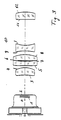
- FIG. 1 shows a lens section through an optical system which has a collimator objective (surface 1 to 5) and two cylindrical lenses (surface 6 and 7 or 8 and 9) constructed in the usual way.
- the surfaces 10 and 11 belong to a plane-parallel plate, which can serve as a filter, etc.
- the cover glass of the laser diode is designated by 12 and 13 and the radiating surface of the laser diode by 14.
- FIG. 2 shows the areas 6 to 14 of the system shown in FIG. 1 on an enlarged scale.
- the cylindrical lenses have a "plan effect" in a section of the cylinder surface, i.e. a radius of the cylindrical lenses is infinite.
- the other radius is selected in accordance with the astigmatism value to be corrected and, in the exemplary embodiment shown, can typically be varied between 600 mm and 5000 mm in order to obtain different compensation ranges.
- the other surface of the two cylindrical lenses i.e. the area without a cylindrical effect is a plan area. Therefore, all radii of curvature of the cylindrical lenses are given in the table below with "" ".
- the cylindrical lens formed by the surfaces 6 and 7 can be displaced in the direction of the optical axis 0, while the second cylindrical lens (formed by surfaces 8 and 9) is arranged to be stationary.
- surfaces 6 and / or 9 will be selected as cylinder surfaces if comparatively large astigmatism values have to be corrected.
- Ri is the radius of curvature of the surface i (in mm)
- di is the vertex distance of the surfaces (i + 1) and i (in mm)
- the surfaces 7 and 8 are cylindrical surfaces. In one main section these areas have the radius ⁇ , in the other main section the radius can vary between approx. 600 mm and 5000 mm depending on the light source used.
- the selected radius depends on the astigmatism to be compensated for, the displacement path in the divergent beam path determined by the available outer diameter of the cylinder axes and the desired positioning tolerance as well as manufacturing options. The selection of an appropriate radius is possible at any time for a specialist working in the relevant field.
- the cylinder axes are perpendicular to one another in the exemplary embodiment shown. If necessary, however, an additional possibility of rotating the cylinder axes about the optical axis 0 can be provided. Is too it is possible to select the individual radii of the cylindrical lenses in such a way that the beam cross section is also corrected from elliptical to circular, as is the case with the second exemplary embodiment of the invention.
- FIG. 3 shows a lens section through an optical system for beam shaping according to the invention, which has a laser diode L with a cover glass (areas 1 and 2) and a collimator lens (areas 3 to 8) constructed in the usual way and two cylindrical lenses (areas 9 and 10 or 11 and 12).
- one cylindrical lens (surfaces 9 and 10) has two cylindrical surfaces and the other cylindrical lens (surfaces 11 and 12) a cylindrical surface (12) and a flat surface (11). All cylinder surfaces have a "plan effect" in one section, ie a radius of the cylinder lenses is infinite. Therefore, only the other section is given in the table.
- the angle ⁇ 0 °.
- the two lenses can be rotated by "a few degrees" against one another.
- Ri is the radius of curvature of the surface i (in mm)
- di is the vertex distance of the surfaces (i + 1) and i (in mm)
- the focal length is standardized to 10mm, the actual focal length is approx. 9mm.
Landscapes
- Physics & Mathematics (AREA)
- General Physics & Mathematics (AREA)
- Optics & Photonics (AREA)
- Lenses (AREA)
- Semiconductor Lasers (AREA)
- Optical Head (AREA)
Abstract
Description
- Die Erfindung bezieht sich auf ein optisches System mit einer astigmatischen Lichtquelle, die ein Lichtbündel mit elliptischen Strahlquerschnitt emitiert, einer Kollimatorlinse, zum Kollimieren der Lichtbündel der Lichtquelle und wenigstens zwei zylindrischen Linsen-Elementen, die ein afokales System bilden und eine Änderung der Form des Strahlquerschnittes des aus der Kollimatorlinse austretenden Lichtbündels und eine Korrektur des Astigmatismus der Lichtquelle bewirken.
- Das Licht einer Reihe von Lichtquellen, darunter der gegenwärtig immer mehr an Bedeutung gewinnenden Laserdioden, scheint in unterschiedlichen Ebenen von "Punktlichtquellen" auszugehen, die in Richtung der optischen Achse einen Abstand aufweisen. Diesen Abstand, den man auch als astigmatische Differenz bezeichnet, beträgt bei gegenwärtig gebräuchlichen Laserdioden einige »m. Diese astigmatische Differenz führt bei einer Kollimation des Lichtbündels beispielsweise von Laserdioden mit üblichen Kollimatoren zu einer "nicht punktförmigen" Abbildung, die insbesondere bei Laserscannern oder sog. "Light Pen's" störend ist. Deshalb ist es in der Regel erforderlich, eine Astigmatismuskorrektur vorzusehen.
- Darüberhinaus haben Laserdioden häufig in unterschiedlichen Ebenen verschiedene Abstrahlwinkel. Kollimiert man ein derartiges Lichtbündel mit einem herkömlichen Kollimator, so erhält man ein Lichtbündel mit nicht-kreisförmigen Querschnitt. Diese Abweichung von der Kreisform ist jedoch in einer Reihe von Anwendungsfällen nicht erwünscht.
- Ergänzend wird hierzu auf den Übersichtsartikel "Specifying Laser Diode Optics" in Laser Focus/Electro-Optics, March 1984, S.44 ff verwiesen. Auf diesen Artikel wird im übrigen zur Erläuterung aller hier nicht näher erläuterten Begriff ausdrücklich Bezug genommen !
- Zur Astigmatismuskorrektur ist es beispielsweise aus der DE-C-22 66 032 oder aus dem vorstehend genannten Übersichtsartikel bekannt, in den Strahlengang eine Zylinderlinse einzubringen, die den "astigmatischen Fehler" für eine bestimmte astigmatische Differenz zumindest vermindert.
- Ferner ist in der US-A-3 396 344 vorgeschlagen worden, in den parallelen Strahlengang nach dem Kollimator zwei Zylinderlinsen einzubringen.
- Weitere Vorschläge zur Astigmatismuskorrektur sind in der US-A-4 203 653 und der US-A-4 318 594 veröffentlicht. In diesen Druckschriften ist ein optisches System mit einem optischen Glied mit astigmatischer Wirkung und mit einem Abbildungssystem beschrieben. Das optische Glied mit astigmatischer Wirkung weist zwei Zylinderlinsen-Elemente mit astigmatischer Wirkung auf.
- Diese Möglichkeit der Astigmatismuskorrektur hat jedoch keine größere Verbreitung gefunden. Statt dessen ist vorgeschlagen worden, den Astigmatismus von Laserdioden mit zwei anamorphotischen Prismen sowie gegebenenfalls einer zusätzlichen Zylinderlinse zu korrigieren. Hierzu wird auf den bereits genannten Übersichtsartikel sowie auf den Laserkopf der Fa. Melles Griot verwiesen.
- Nun haben aber beispielsweise Laserdioden nicht nur von Bauart zu Bauart, sondern auch innerhalb einer Baureihe aufgrund von Herstelltoleranzen zwischen verschiedenen Fertigungschargen unterschiedliche astigmatische Differenzen. Darüberhinaus ändern sich die astigmatischen Differenzen aufgrund von Alterungserscheinungen im Laufe der üblichen Einsatzzeit einer Laserdiode.
- Deshalb wäre es wünschenswert, den astigmatischen Korrektionswert einstellen zu können. Dies ist bei den bekannten Systemen nicht oder nur in einer Weise möglich, daß bei der Einstellung der Astigmatismuskorrektur beide Abstrahlrichtungen beeinflußt werden, so daß die Kollimation zusätzlich "nachgestellt" werden muß.
- Zur Änderung des Querschnitts des Lichtbündels ist es aus dem bereits erwähnten Übersichtsartikel "Specifying Laser Diode Optics" in Laser Focus/Electro-Optics, March 1984, S.44 ff bekannt, zwei anamorphotischen Prismen zu verwenden. Ferner ist in der ebenfalls bereits erwähnten US-PS 3 396 344 vorgeschlagen worden, in den parallelen Strahlengang nach dem Kollimator zwei Zylinderlinsen einzubringen, von denen eine eine kurze Brennweite und die andere eine lange Brennweite aufweist. Diese Möglichkeit der Strahlquerschnittskorrektur hat jedoch keine größere Verbreitung gefunden.
- Statt dessen ist in praktischen Realisierung immer versucht worden, eine Strahlquerschnittskorrektur von Laserdioden mit zwei anamorphotischen Prismen vorzunehmen.
Hierzu wird exemplarisch auf den Laserkopf der Fa. Melles Griot verwiesen. Derartige Laserköpfe haben aber den Nachteil, daß sie aufgrund der beiden anamorphotischen Prismen eine vergleichsweise große Bauform und großes Gewicht haben. Ferner ist die Einhaltung des Prismenwinkel fertigungstechnisch sehr aufwendig. - Der Erfindung liegt die Aufgabe zugrunde, ein optisches System zur Abbildung des Lichts von Lichtquellen, die insbesondere in unterschiedlichen Ebenen verschiedene Abstrahlwinkel aufweisen können, anzugeben, dessen Astigmatismus-Korrektionswert zur Korrektur variierender astigmatischer Differenzen einstellbar ist.
- Ferner soll erfindungsgemäß ein optisches System zur Änderung der Form des Strahlquerschnittes von Lichtbündeln und insbesondere zur Änderung der Form des Strahlquerschnittes von Laserdioden, angegeben werden, das eine kurze Bauform aufweist.
- Diese Aufgabe wird erfindungs gemäß durch die Merkmale des Anspruchs 1 gelöst.
- Im Anspruch 3 ist ein bevorzugter Brennweitenbereich für die Systeme gemäß den Ansprüche 1 und 2 angegeben, gemäß dem
6 mm < |f₁| < 50 mm bei Aufweitung
6 mm < |f₂| < 50 mm bei Komprimierung
des Strahls ist. - Bei der Verwendung von Zylinderlinsen ist es selbstverständlich möglich, die Fläche ohne Zylinderwirkung als normale sphärische oder asphärische Fläche auszubilden. Gemäß Anspruch 4 ist es jedoch bevorzugt, wenn diese Fläche eine Planfläche ist.
- Die Erfindung wird nachstehend anhand eines Ausführungsbeispiels unter Bezugnahme auf die Zeichnung näher beschrieben, in der zeigen:
- Figur 1
- einen Linsenschnitt durch ein optisches System zur Astigmatismuskorrektion,
- Figur 2
- vergrößert einen Teil des Systems gemäß Figur 1, und
- Figur 3
- einen Linsenschnitt durch ein erfindungsgemäßes optisches System zur Strahlformung.
- Fig. 1 zeigt einen Linsenschnitt durch ein optisches System, das ein in üblicher Weise aufgebautes Kollimatorobjektiv (Fläche 1 bis 5) sowie zwei Zylinderlinsen (Fläche 6 und 7 bzw. 8 und 9) aufweist. Die Flächen 10 und 11 gehören zu einer planparallelen Platte, die beispielsweise als Filter etc. dienen kann. Mit 12 und 13 ist das Deckglas der Laserdiode und mit 14 die strahlende Fläche der Laserdiode bezeichnet.
- Fig. 2 zeigt vergrößert die Flächen 6 bis 14 des in Fig. 1 dargestellten Systems.
- Bei dem dargestellten Ausführungsbeispiel weisen die Zylinderlinsen in einem Schnitt der Zylinderfläche eine "Planwirkung" auf, d.h. ein Radius der Zylinderlinsen ist unendlich. Der andere Radius wird entsprechend dem zu korrigierenden Astigmatismuswert gewählt und kann bei dem dargestellten Ausführungsbeispiel typischerweise zwischen 600 mm und 5000 mm variiert werden, um unterschiedliche Kompensationsbereiche zu erhalten. Ferner ist die andere Fläche der beiden Zylinderlinsen, d.h. die Fläche ohne Zylinderwirkung eine Plantläche. Deshalb sind in der nachfolgenden Tabelle sämtliche Krümmungsradien der Zylinderlinsen mit "∞" angegeben.
- Bei dem dargestellten Ausführungsbeispiel ist die von den Flächen 6 und 7 gebildete Zylinderlinse in Richtung der optischen Achse 0 verschiebbar, während die zweite Zylinderlinse (gebildet von Flächen 8 und 9) feststehend angeordnet ist.
- Die Wahl der Zylinderfläche erfolgt unter dem Gesichtspunkt, daß "flache" Radien schwieriger als "krümmere" Radien herzustellen sind:
- Sollen vergleichsweise kleine Astigmatismuswerte korrigiert werden, so ist es bevorzugt, als Zylinderfläche die beiden einander zugekehrten Flächen 7 und 8 zu wählen, da dann das Gesamtsystem bei nahezu vollständigem Zusammenschieben der beiden Zylinderlinsen einen Astigmatismus nahe Null hat.
- Andererseits wird man als Zylinderflächen die Flächen 6 und/oder 9 wählen, wenn vergleichsweise große Astigmatismuswerte zu korrigieren sind.
- In der nachfolgenden Tabelle sind exemplarisch numerische Werte für ein Ausführungsbeispiel ohne Beschränkung des allgemeinen Erfindungsgedankens angegeben.
- Dabei sind mit Ri der Krümmungsradius der Fläche i (in mm), mit di der Scheitelabstand der Flächen (i+1) und i (in mm) und mit ni bzw. vi die Brechzahl und die Abbe'sche Zahl des Materials zwischen den Flächen i und (i+1) für die d-Linie bezeichnet. (ni=1 bedeutet einen Luftraum.)
- Bei dem gezeigten Ausführungsbeispiel sind die Flächen 7 und 8 Zylinderflächen. In einem Hauptschnitt haben diese Flächen den Radius ∞, in dem anderen Hauptschnitt kann der Radius je nach eingesetzter Lichtquelle zwischen ca 600 mm und 5000 mm variieren. Der gewählte Radius richtet sich nach dem zu kompensierenden Astigmatismus, dem durch den verfügbaren Außendurchmesser der Zylinderachsen bestimmten Verschiebeweg im divergenten Strahlengang und der gewünschten Positioniertoleranz sowie Fertigungsmöglichkeiten. Die Wahl eines entsprechenden Radius ist einem auf dem einschlägigen Gebiet tätigen Fachmann jederzeit möglich.
- Im Normalfall stehen die Zylinderachsen bei dem gezeigten Ausführungsbeispiel aufeinander senkrecht. Gegebenenfalls kann jedoch eine zusätzliche Drehmöglichkeit der Zylinderachsen um die optische Achse 0 vorgesehen werden. Auch ist es möglich, die einzelnen Radien der Zylinderlinsen so zu wählen, daß zusätzlich auch eine Korrektion des Strahlquerschnittes von elliptisch auf kreisförmig erfolgt, wie dies bei dem zweiten Ausführungsbeispiel der Erfindung der Fall ist.

- Fig. 3 zeigt einen Linsenschnitt durch ein erfindungsgemäßes optisches System zur Strahlformung, das eine Laserdiode L mit einem Deckglas (Flächen 1 und 2) und ein in üblicher Weise aufgebautes Kollimatorobjektiv (Fläche 3 bis 8) sowie zwei Zylinderlinsen (Fläche 9 und 10 bzw. 11 und 12) aufweist. Bei dem dargestellten Ausführungsbeispiel weist eine Zylinderlinse (Flächen 9 und 10) zwei Zylinderflächen und die andere Zylinderlinse (Flächen 11 und 12) eine Zylinderfläche (12) und eine Planfläche (11) auf. Sämtliche Zylinderflächen haben in einem Schnitt eine "Planwirkung" auf, d.h. ein Radius der Zylinderlinsen ist unendlich. In der Tabelle ist deshalb nur der andere Schnitt angegeben. Dabei ist der Winkel α=0°. Zur Korrektur von Fertigungsfehlern insbesondere der Zylinderlinse mit zwei astigmatischen Flächen können die beiden Linsen um "einige Grad" gegeneinander verdreht werden.
- In der nachfolgenden Tabelle sind exemplarisch numerische Werte für ein Ausführungsbeispiel ohne Beschränkung des allgemeinen Erfindungsgedankens angegeben. Dabei sind mit Ri der Krümmungsradius der Fläche i (in mm), mit di der Scheitelabstand der Flächen (i+1) und i (in mm) und mit ni bzw. vi die Brechzahl und die Abbe'sche Zahl des Materials zwischen den Flächen i und (i+1) für die d-Linie bezeichnet (ni=1 bedeutet einen Luftraum.). Die Brennweite ist auf 10mm normiert, die tatsächliche Brennweite ist ca 9mm.


- Vorstehend ist die Erfindung ohne Beschränkung des allgemeinen Erfindungsgedankens beschrieben worden.
Claims (4)
- Optisches System mit
einer astigmatischen Lichtquelle, die ein Lichtbündel mit elliptischen Strahlquerschnitt emitiert;
einer Kollimatorlinse, zum Kollimieren der Lichtbündel der Lichtquelle;
wenigstens zwei zylindrischen Linsen-Elementen, die ein afokales System bilden und eine Änderung der Form des Strahlquerschnittes des aus der Kollimatorlinse austretenden Lichtbündels und eine Korrektur des Astigmatismus der Lichtquelle bewirken,
dadurch gekennzeichnet, daß ein Manipulatorelement zum Verdrehen der Zylinderachsen der zwei zylindrischen Linsen-Elemente bis zu einem Winkel von maximal 20° zueinander vorgesehen ist, und daß entweder die Brennweite des in Strahlrichtung gesehen ersten zylindrischen Linsen-Elements zum Aufweiten des von der Kollimator-Linse austretenden Lichtbündels eine Brennweite hat, die zwischen -300mm und -1mm liegt oder daß die Brennweite des in Strahlrichtung gesehenen zweiten zylindrischen Linsen-Elements zum Komprimieren des von der Kollimator-Linse austretenden Lichtbündels eine Brennweite hat, die zwischen 1mm und 300mm liegt. - Optisches System nach Anspruch 1,
dadurch gekennzeichnet, daß wenigstens eines der Linsen-Elemente zwei Zylinderflächen (9,10) aufweist. - Optisches System nach Anspruch 1 oder 2,
dadurch gekennzeichnet, daß entweder die Brennweite des in Strahlrichtung gesehen ersten zylindrichen Linsen-Elements zum Aufweiten des von der Kollimator-Linse austretenden Lichtbündels eine Brennweite hat, die zwischen -50 mm und -6 mm liegt oder die Brennweite des in Strahlrichtung gesehen zweiten zylindrischen Linsen-Elements zum Komprimieren des von der Kollimator-Linse austretenden Lichtbündels eine Brennweite hat, die zwischen 6 mm und 50 mm liegt. - Optisches System nach einem der Ansprüche 1 bis 3, dadurch gekennzeichnet, daß wenigstens eines der Linsen-Elemente eine Planfläche (11) aufweist.
Applications Claiming Priority (9)
| Application Number | Priority Date | Filing Date | Title |
|---|---|---|---|
| DE3912496 | 1989-04-15 | ||
| DE3912496 | 1989-04-15 | ||
| DE3916606 | 1989-05-22 | ||
| DE3916606 | 1989-05-22 | ||
| DE3916658 | 1989-05-22 | ||
| DE19893916658 DE3916658C2 (de) | 1989-04-15 | 1989-05-22 | Optisches System zur Abbildung des Lichts einer Lichtquelle |
| DE19893919484 DE3919484A1 (de) | 1989-04-15 | 1989-06-14 | Optisches system zur aenderung der form des strahlquerschnittes von lichtbuendeln |
| DE3919484 | 1989-06-14 | ||
| PCT/DE1990/000285 WO1990013054A1 (de) | 1989-04-15 | 1990-04-12 | Optisches system zur abbildung des lichts von lichtquellen |
Publications (2)
| Publication Number | Publication Date |
|---|---|
| EP0422169A1 EP0422169A1 (de) | 1991-04-17 |
| EP0422169B1 true EP0422169B1 (de) | 1995-07-12 |
Family
ID=27434566
Family Applications (1)
| Application Number | Title | Priority Date | Filing Date |
|---|---|---|---|
| EP90906118A Expired - Lifetime EP0422169B1 (de) | 1989-04-15 | 1990-04-12 | Optisches system zur abbildung des lichts von lichtquellen |
Country Status (4)
| Country | Link |
|---|---|
| US (1) | US5307208A (de) |
| EP (1) | EP0422169B1 (de) |
| DE (1) | DE59009396D1 (de) |
| WO (1) | WO1990013054A1 (de) |
Families Citing this family (7)
| Publication number | Priority date | Publication date | Assignee | Title |
|---|---|---|---|---|
| EP0587914A4 (en) * | 1992-04-06 | 1994-09-14 | Furukawa Electric Co Ltd | Asymmetric lens |
| US5706140A (en) * | 1993-09-06 | 1998-01-06 | Kansei Corp. | Optical distance measuring equipment |
| US5946143A (en) * | 1998-05-05 | 1999-08-31 | Raytheon Company | Dynamic aberration correction of conformal/aspheric domes and windows for missile and airborne fire control applications |
| ATE480792T1 (de) * | 2003-10-30 | 2010-09-15 | Limo Patentverwaltung Gmbh | Anordnung und vorrichtung zur optischen strahlbündeltransformation |
| ES2399604B1 (es) * | 2010-07-08 | 2014-03-11 | Jose Luis SEOANE PENA | Sistema óptico de muy alta flexibilidad para el ajuste del campo de la iluminación en luminarias y dispositivos de alumbrado |
| FR3087778B1 (fr) * | 2018-10-26 | 2021-07-23 | Arkema France | Composition de polymere adaptee pour moulage par injection comprenant des particules et un colorant, son procede de preparation et son utilisation |
| HUE054958T2 (hu) * | 2019-02-04 | 2021-10-28 | Grieshaber Vega Kg | Antenna elrendezés |
Family Cites Families (7)
| Publication number | Priority date | Publication date | Assignee | Title |
|---|---|---|---|---|
| US3051051A (en) * | 1958-07-11 | 1962-08-28 | Caps Ltd | Optical justifying means |
| GB1290738A (de) * | 1970-04-20 | 1972-09-27 | ||
| GB1392086A (en) * | 1972-03-29 | 1975-04-23 | Rank Organisation Ltd | Lenses |
| US4203652A (en) * | 1977-02-15 | 1980-05-20 | Canon Kabushiki Kaisha | Beam shaping optical system |
| US4318594A (en) * | 1977-02-15 | 1982-03-09 | Canon Kabushiki Kaisha | Beam shaping optical system |
| US4555164A (en) * | 1983-03-03 | 1985-11-26 | Designs For Vision, Inc. | Anamorphic lens system increasing the field of view for the visually handicapped |
| US4826269A (en) * | 1987-10-16 | 1989-05-02 | Spectra Diode Laboratories, Inc. | Diode laser arrangement forming bright image |
-
1990
- 1990-04-12 WO PCT/DE1990/000285 patent/WO1990013054A1/de not_active Ceased
- 1990-04-12 DE DE59009396T patent/DE59009396D1/de not_active Expired - Fee Related
- 1990-04-12 EP EP90906118A patent/EP0422169B1/de not_active Expired - Lifetime
- 1990-04-12 US US07/613,771 patent/US5307208A/en not_active Expired - Fee Related
Also Published As
| Publication number | Publication date |
|---|---|
| US5307208A (en) | 1994-04-26 |
| DE59009396D1 (de) | 1995-08-17 |
| EP0422169A1 (de) | 1991-04-17 |
| WO1990013054A1 (de) | 1990-11-01 |
Similar Documents
| Publication | Publication Date | Title |
|---|---|---|
| DE19948889C1 (de) | Vorrichtung zur Symmetrierung der Strahlung von linearen optischen Emittern und Verwendung der Vorrichtung | |
| DE3852416T2 (de) | Anamorphotische Linse. | |
| DE3217776C2 (de) | Stereomikroskop | |
| DE69219248T2 (de) | Zoomobjektiv | |
| DE102004002221B3 (de) | Vorrichtung zur optischen Strahltransformation einer linearen Anordnung mehrerer Lichtquellen | |
| DE3781129T2 (de) | Abbildendes spektrometer. | |
| CH656013A5 (de) | Afokales linsenfernrohr mit zwei vergroesserungseinstellungen. | |
| DE4122817A1 (de) | Automatische linsenmesseinrichtung | |
| DE102016102591A1 (de) | Vorrichtung zur Formung von Laserstrahlung | |
| DE69809880T2 (de) | Objektiv mit konstanter brennweite im sichtbaren- und im ir-bereich | |
| EP1245985B1 (de) | Bildübertragung mit einer Optik vom Offner-Typ | |
| WO1990013054A1 (de) | Optisches system zur abbildung des lichts von lichtquellen | |
| DE69425514T2 (de) | F-Theta Linse | |
| EP0642676A1 (de) | Abtastobjektiv | |
| DE4314499A1 (de) | Silhouettierungsfreie 4-Spiegel-Systeme für Teleskope; Tetra-Schiefspiegler 2. Art | |
| DE69014553T2 (de) | Optisches Korrektionsverfahren für Abbildungsfehler die durch aussermittigen Gebrauch bei sphärischen Kuppeln hervorgerufen werden. | |
| DE3919484A1 (de) | Optisches system zur aenderung der form des strahlquerschnittes von lichtbuendeln | |
| DE4301291C2 (de) | Universeller Zweispiegelkorrektor für Cassegrain- und Ritchey- Chretien -Spiegelsysteme | |
| DE3916658C2 (de) | Optisches System zur Abbildung des Lichts einer Lichtquelle | |
| DE2217192A1 (de) | Linsensystem mit großer Öffnung und langer Brennweite | |
| DD298032A5 (de) | Optisches system zur abbildung des lichts von lichtquellen | |
| EP0721601B1 (de) | Scansystem | |
| DE102013007541B4 (de) | Zylinderlinsenarray und Optikbaugruppe mit Zylinderlinsenarray | |
| DE2629820A1 (de) | Vorrichtung zur parallelen ausrichtung mehrerer optischer achsen | |
| DE102006027126B3 (de) | Vorrichtung zur punktförmigen Fokussierung von Strahlung |
Legal Events
| Date | Code | Title | Description |
|---|---|---|---|
| PUAI | Public reference made under article 153(3) epc to a published international application that has entered the european phase |
Free format text: ORIGINAL CODE: 0009012 |
|
| 17P | Request for examination filed |
Effective date: 19901204 |
|
| AK | Designated contracting states |
Kind code of ref document: A1 Designated state(s): AT BE CH DE DK ES FR GB IT LI LU NL SE |
|
| RBV | Designated contracting states (corrected) |
Designated state(s): DE FR GB IT NL |
|
| 17Q | First examination report despatched |
Effective date: 19931206 |
|
| GRAA | (expected) grant |
Free format text: ORIGINAL CODE: 0009210 |
|
| AK | Designated contracting states |
Kind code of ref document: B1 Designated state(s): DE FR GB IT NL |
|
| PG25 | Lapsed in a contracting state [announced via postgrant information from national office to epo] |
Ref country code: IT Free format text: LAPSE BECAUSE OF FAILURE TO SUBMIT A TRANSLATION OF THE DESCRIPTION OR TO PAY THE FEE WITHIN THE PRE;WARNING: LAPSES OF ITALIAN PATENTS WITH EFFECTIVE DATE BEFORE 2007 MAY HAVE OCCURRED AT ANY TIME BEFORE 2007. THE CORRECT EFFECTIVE DATE MAY BE DIFFERENT FROM THE ONE RECORDED.SCRIBED TIME-LIMIT Effective date: 19950712 Ref country code: NL Free format text: LAPSE BECAUSE OF FAILURE TO SUBMIT A TRANSLATION OF THE DESCRIPTION OR TO PAY THE FEE WITHIN THE PRESCRIBED TIME-LIMIT Effective date: 19950712 Ref country code: FR Effective date: 19950712 |
|
| REF | Corresponds to: |
Ref document number: 59009396 Country of ref document: DE Date of ref document: 19950817 |
|
| GBT | Gb: translation of ep patent filed (gb section 77(6)(a)/1977) |
Effective date: 19950720 |
|
| EN | Fr: translation not filed | ||
| NLV1 | Nl: lapsed or annulled due to failure to fulfill the requirements of art. 29p and 29m of the patents act | ||
| PLBE | No opposition filed within time limit |
Free format text: ORIGINAL CODE: 0009261 |
|
| STAA | Information on the status of an ep patent application or granted ep patent |
Free format text: STATUS: NO OPPOSITION FILED WITHIN TIME LIMIT |
|
| 26N | No opposition filed | ||
| PGFP | Annual fee paid to national office [announced via postgrant information from national office to epo] |
Ref country code: GB Payment date: 19980408 Year of fee payment: 9 |
|
| PG25 | Lapsed in a contracting state [announced via postgrant information from national office to epo] |
Ref country code: GB Free format text: LAPSE BECAUSE OF NON-PAYMENT OF DUE FEES Effective date: 19990412 |
|
| GBPC | Gb: european patent ceased through non-payment of renewal fee |
Effective date: 19990412 |
|
| PGFP | Annual fee paid to national office [announced via postgrant information from national office to epo] |
Ref country code: DE Payment date: 20030122 Year of fee payment: 14 |
|
| PG25 | Lapsed in a contracting state [announced via postgrant information from national office to epo] |
Ref country code: DE Free format text: LAPSE BECAUSE OF NON-PAYMENT OF DUE FEES Effective date: 20041103 |