EP0421920A1 - Drainagerohr für eine rückspülbare Drainagerohrfilteranlage - Google Patents
Drainagerohr für eine rückspülbare Drainagerohrfilteranlage Download PDFInfo
- Publication number
- EP0421920A1 EP0421920A1 EP90810656A EP90810656A EP0421920A1 EP 0421920 A1 EP0421920 A1 EP 0421920A1 EP 90810656 A EP90810656 A EP 90810656A EP 90810656 A EP90810656 A EP 90810656A EP 0421920 A1 EP0421920 A1 EP 0421920A1
- Authority
- EP
- European Patent Office
- Prior art keywords
- pipe
- air
- openings
- air outlet
- outlet openings
- Prior art date
- Legal status (The legal status is an assumption and is not a legal conclusion. Google has not performed a legal analysis and makes no representation as to the accuracy of the status listed.)
- Ceased
Links
- 238000009434 installation Methods 0.000 title 1
- XLYOFNOQVPJJNP-UHFFFAOYSA-N water Substances O XLYOFNOQVPJJNP-UHFFFAOYSA-N 0.000 claims description 18
- 238000009423 ventilation Methods 0.000 claims description 8
- 239000000706 filtrate Substances 0.000 claims description 6
- 239000000463 material Substances 0.000 claims description 6
- 238000011010 flushing procedure Methods 0.000 abstract description 11
- 238000009827 uniform distribution Methods 0.000 abstract description 4
- 238000013022 venting Methods 0.000 abstract 2
- 238000010926 purge Methods 0.000 description 7
- 238000011001 backwashing Methods 0.000 description 5
- 238000001914 filtration Methods 0.000 description 5
- 239000000356 contaminant Substances 0.000 description 3
- 238000000034 method Methods 0.000 description 3
- 239000000203 mixture Substances 0.000 description 3
- 239000008237 rinsing water Substances 0.000 description 3
- 230000015572 biosynthetic process Effects 0.000 description 2
- 238000009826 distribution Methods 0.000 description 2
- 230000000694 effects Effects 0.000 description 2
- 238000010276 construction Methods 0.000 description 1
- 239000008187 granular material Substances 0.000 description 1
- 230000002028 premature Effects 0.000 description 1
- 230000001960 triggered effect Effects 0.000 description 1
Images

Classifications
-
- B—PERFORMING OPERATIONS; TRANSPORTING
- B01—PHYSICAL OR CHEMICAL PROCESSES OR APPARATUS IN GENERAL
- B01D—SEPARATION
- B01D24/00—Filters comprising loose filtering material, i.e. filtering material without any binder between the individual particles or fibres thereof
- B01D24/02—Filters comprising loose filtering material, i.e. filtering material without any binder between the individual particles or fibres thereof with the filter bed stationary during the filtration
- B01D24/20—Filters comprising loose filtering material, i.e. filtering material without any binder between the individual particles or fibres thereof with the filter bed stationary during the filtration the filtering material being provided in an open container
- B01D24/24—Downward filtration, the container having distribution or collection headers or pervious conduits
-
- B—PERFORMING OPERATIONS; TRANSPORTING
- B01—PHYSICAL OR CHEMICAL PROCESSES OR APPARATUS IN GENERAL
- B01D—SEPARATION
- B01D24/00—Filters comprising loose filtering material, i.e. filtering material without any binder between the individual particles or fibres thereof
- B01D24/46—Regenerating the filtering material in the filter
- B01D24/4631—Counter-current flushing, e.g. by air
Definitions
- the invention relates to a drainage pipe for a backwashing drainage pipe filter system for water treatment, which is placed on the bottom of the filter basin and surrounded by granular filter material, with air outlet openings of small cross-section being evenly distributed in the upper third of the drainage pipe in the direction of its longitudinal axis.
- a drainage pipe of the type mentioned above is known from CH-PS 668 559; In practice it has been shown that the air blown into the tube during backwashing with air and / or an air / water mixture cannot be completely removed from the tube during the subsequent pure water flushing. These air pockets which are not "removed” can lead to sporadic air bursts into the filter medium during a subsequent filtering process. Above all, this has negative effects on the filtration process.
- the residual air that sporadically emerges from the drainage pipes can create channels in the filter medium during the filtration process, which can impair the filtration effect.
- the object of the invention is to provide a drainage pipe which can be virtually completely vented after backwashing with air or an air / water mixture.
- a compressed gas cushion should still be maintained in the case of an air or air / water purge in order to achieve a uniform distribution of the purge air over the entire filter field. It is therefore important to ensure that the diameters of the various air outlet openings are matched to one another so that such an air gas cushion is guaranteed. It has proven to be advantageous if the openings in the apex region of the tube contain at most one tenth of the total cross section of the air outlet openings.
- both of the described requirements for the air outlet openings can be optimally met if the air outlet openings are along the apex line of the tube have diameters of 0.5 to 3 mm, and if furthermore 1 to 12 openings are arranged in the apex line per meter of tube length, with the remaining air outlet openings at a number of 5 to 25 per meter tube length having a diameter of 2 to 8 mm.
- the drainage pipe is connected to a filtrate collecting space via two separate pipes which are led through the bottom of the system; one of these pipes, the connecting pipe, serves the filtrate drain and the flushing water supply from or to the drain pipe, while the other, the ventilation pipe, flushing air is fed into the drain pipe.
- This construction is complex and requires two openings per drainage pipe through the bottom of the filter tank, which is generally made of concrete. According to a further idea of the invention, this effort can be considerably reduced if a ventilation pipe of small diameter is inserted into the connecting pipe, which penetrates the jacket of the connecting pipe near the ceiling of the collecting duct and ends above the level line of the deepest air outlet openings of the drainage pipe.
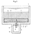
- a drainage pipe 3 is placed on the bottom 1 of a filter basin 4 (FIG. 3) and fixed, for example, by clips or pipe clamps, not shown, anchored in the bottom.
- the tube 3 has a rectangular cross section, which is closed at the top by an arched "ceiling". It is embedded in a granular filter mass 2.
- a number of holes 6 are provided in the bottom 5 of the tube 3 in the direction of its axis. In the longitudinal direction of the tube 3 between or laterally next to these holes, ribs 7 are arranged, by means of which the bottom 5 is held at a distance a (FIG. 1) from the bottom 1 of the basin 4.
- the height h of this distance is matched to the grain size of the filter mass 2 surrounding the drainage pipes 3 in the filter basin 4 such that no grains can get into the drainage pipe 3.
- the filter mass 2 can consist both of a material of uniform grain size and - which is not expressly shown - under certain circumstances from a relatively fine-grained first material, the actual filter material, and from a coarser-grained support layer in which the drainage pipes 3 are embedded.
- the filtrate is drained in the filtration mode and the outlet of the rinsing water in the rinsing mode.
- first air outlet openings 8 are arranged in a row running in the direction of the pipe axis, from which the majority of the purging air emerges in the purging mode.
- a blockage of individual of these openings 8 by grains of the filter mass 2 prevents a groove 9 located in front of the openings 8 on the outside, the width of which corresponds to the diameter of the openings; this is also smaller than the grain size of the granular filter material in the filter mass 2.
- a further row of air outlet openings 15 runs in the apex of the curved ceiling, through which the drain pipe 3 can be at least almost completely vented after an air and / or an air / water purge.
- the invention is not limited to pipes 3 with vaulted or roof-top ceilings with clear apex lines; in the case of pipes with other ceilings, the openings 15 are each arranged at the "highest" point in the cross section.
- the holes 6 for the passage of water and the openings 8 and 15 for the air outlet are coordinated with one another in terms of their number, distribution and diameter such that air and water simultaneously emerge from the drainage pipes 3 into the filter mass 2 during an air / water flushing process .
- the total opening cross-section of the air outlet openings 8 and 15 is distributed over the two "types" of the openings 8 and 15 in such a way that an air cushion is maintained in the pipe 3, by means of which a uniform distribution of the air over the entire pipe length is ensured.
- the openings 15 have a diameter of approximately 1.3 mm
- the openings 8 have a diameter of approximately 4 mm.
- 6-7 openings 15 and 14 openings 8 are distributed per meter of pipe length.
- the opening cross section of the openings 15 is thus about 1/20 of that of the openings 8.
- Fig. 3 shows a drainage pipe in a filter basin 4 during the backwash phase of the filter.
- all drainage pipes 3 of a basin are provided with connecting pipes 10, which lead through their bottom 5 and lead through the bottom 1 of the filter basin into a collecting channel 13.
- the collecting duct 13 is arranged and extends under the middle of the dimension of the filter basin 4 running parallel to the drainage pipes. over the entire filter length. It is connected to supply lines (not shown) for purge air and backwash water.
- the connecting pipe 10 ends near or in the bottom 5 of the drain pipe 3 and on the one hand enables the filtrate to be drawn off from the pipe 3, on the other hand it feeds the drain pipes 3 from the channel 13 with rinsing water.
- the supply of the purge air to the channel 13 in a drainage pipe 3 serves a ventilation pipe 11 of small diameter, which is inserted into the connecting pipe 10 and the jacket of the connecting pipe 10 near the ceiling of the
- Collective channel 13 penetrates; it ends above the level line of the deepest air outlet openings 8 of the drainage pipe 3. Its cross section is dimensioned such that the pressure drop in this pipe 11 leads to the formation of a compressed air cushion 12 in the channel 13. This air cushion ensures a uniform air distribution over all drainage pipes 3 over the entire filter length of a filter field.
- the cross section of the tube 11 is approximately 6% of that of the tube 10.
- the pressure drop at the air outlet openings 8 and 15 of a drainage pipe 3 leads to the formation of the air cushion mentioned within this pipe and thus ensures a uniform distribution of the air over the entire pipe length or filter width.
Landscapes
- Chemical & Material Sciences (AREA)
- Chemical Kinetics & Catalysis (AREA)
- Filtration Of Liquid (AREA)
Applications Claiming Priority (2)
| Application Number | Priority Date | Filing Date | Title |
|---|---|---|---|
| CH3578/89 | 1989-10-02 | ||
| CH3578/89A CH679126A5 (enExample) | 1989-10-02 | 1989-10-02 |
Publications (1)
| Publication Number | Publication Date |
|---|---|
| EP0421920A1 true EP0421920A1 (de) | 1991-04-10 |
Family
ID=4259015
Family Applications (1)
| Application Number | Title | Priority Date | Filing Date |
|---|---|---|---|
| EP90810656A Ceased EP0421920A1 (de) | 1989-10-02 | 1990-08-30 | Drainagerohr für eine rückspülbare Drainagerohrfilteranlage |
Country Status (2)
| Country | Link |
|---|---|
| EP (1) | EP0421920A1 (enExample) |
| CH (1) | CH679126A5 (enExample) |
Cited By (2)
| Publication number | Priority date | Publication date | Assignee | Title |
|---|---|---|---|---|
| WO1997018881A1 (de) * | 1995-11-17 | 1997-05-29 | Ct Umwelttechnik Ag | Rückspülbares filterbecken mit drainagerohren |
| US20180333659A1 (en) * | 2017-05-16 | 2018-11-22 | Xylem Water Solutions Zelienople Llc | Self-Cleaning, Groutless, Filter Underdrain |
Citations (6)
| Publication number | Priority date | Publication date | Assignee | Title |
|---|---|---|---|---|
| DE449522C (de) * | 1924-08-30 | 1927-09-16 | Breitschuh & Vorbrodt | Vorrichtung zum Saettigen der Luft |
| US1747470A (en) * | 1927-03-29 | 1930-02-18 | Wm B Scaife & Sons Co | Water-treating apparatus |
| US1998279A (en) * | 1934-03-30 | 1935-04-16 | Hungerford And Terry Inc | Filter |
| DE647368C (de) * | 1935-01-25 | 1937-07-02 | Oskar Brandes | Vorrichtung zum Rueckspuelen von Fluessigkeitsfiltern |
| US3544457A (en) * | 1968-03-28 | 1970-12-01 | Ethyl Corp | Process and apparatus for fluid treatment |
| CH668559A5 (de) * | 1986-02-11 | 1989-01-13 | Sulzer Ag | Drainagerohr in einer rueckspuelbaren drainagerohr-filteranlage. |
Family Cites Families (1)
| Publication number | Priority date | Publication date | Assignee | Title |
|---|---|---|---|---|
| DE499522C (de) * | 1924-01-29 | 1930-06-07 | William Paterson | Filter mit Waschwasserverteilungskanaelen |
-
1989
- 1989-10-02 CH CH3578/89A patent/CH679126A5/de not_active IP Right Cessation
-
1990
- 1990-08-30 EP EP90810656A patent/EP0421920A1/de not_active Ceased
Patent Citations (6)
| Publication number | Priority date | Publication date | Assignee | Title |
|---|---|---|---|---|
| DE449522C (de) * | 1924-08-30 | 1927-09-16 | Breitschuh & Vorbrodt | Vorrichtung zum Saettigen der Luft |
| US1747470A (en) * | 1927-03-29 | 1930-02-18 | Wm B Scaife & Sons Co | Water-treating apparatus |
| US1998279A (en) * | 1934-03-30 | 1935-04-16 | Hungerford And Terry Inc | Filter |
| DE647368C (de) * | 1935-01-25 | 1937-07-02 | Oskar Brandes | Vorrichtung zum Rueckspuelen von Fluessigkeitsfiltern |
| US3544457A (en) * | 1968-03-28 | 1970-12-01 | Ethyl Corp | Process and apparatus for fluid treatment |
| CH668559A5 (de) * | 1986-02-11 | 1989-01-13 | Sulzer Ag | Drainagerohr in einer rueckspuelbaren drainagerohr-filteranlage. |
Cited By (4)
| Publication number | Priority date | Publication date | Assignee | Title |
|---|---|---|---|---|
| WO1997018881A1 (de) * | 1995-11-17 | 1997-05-29 | Ct Umwelttechnik Ag | Rückspülbares filterbecken mit drainagerohren |
| US20180333659A1 (en) * | 2017-05-16 | 2018-11-22 | Xylem Water Solutions Zelienople Llc | Self-Cleaning, Groutless, Filter Underdrain |
| US10881989B2 (en) * | 2017-05-16 | 2021-01-05 | Xylem Water Solutions Zelienople Llc | Self-cleaning, groutless, filter underdrain |
| AU2018268843B2 (en) * | 2017-05-16 | 2024-03-07 | Xylem Water Solutions Zelienople Llc | Self-cleaning, groutless, filter underdrain |
Also Published As
| Publication number | Publication date |
|---|---|
| CH679126A5 (enExample) | 1991-12-31 |
Similar Documents
| Publication | Publication Date | Title |
|---|---|---|
| DE69417374T2 (de) | Membranbioreaktor mit einem Gasliftsystem | |
| DE3850792T2 (de) | Verfahren und Vorrichtung zum Filtrieren. | |
| EP1317318B1 (de) | Membranfilter für die wasseraufbereitung | |
| DE69627203T2 (de) | Flotationsvorrichtung und verfahren | |
| EP0066921A2 (de) | Filterelement | |
| DE2737039A1 (de) | Vorrichtung zur verteilung und zum sammeln von fliessmittel in entgegengesetzten richtungen mit unterschiedlichen fliessgeschwindigkeiten | |
| DE915490C (de) | Filtriervorrichtung | |
| WO1992001500A1 (de) | Filtriervorrichtung für thermoplastisches kunststoffmaterial | |
| DE2529977B2 (de) | Vorrichtung mit Membranen auf rohrförmigen Abstützungen zum Behandeln von Fluiden | |
| DE2532528C3 (de) | Verfahren zur Einstellung eines bestimmten Verteilungsgesetzes des Durchflusses in einem Mediumsstrom, Vorrichtung zur Durchführung des Verfahrens und Verwendung des Verfahrens bzw. der Vorrichtung | |
| DE69503080T2 (de) | Filter zur Reinigung von Wasser | |
| EP0421920A1 (de) | Drainagerohr für eine rückspülbare Drainagerohrfilteranlage | |
| AT406343B (de) | Vorrichtung zur aufbereitung einer flüssigkeit, insbesondere zur reinigung von wasser | |
| EP0232448B1 (de) | Drainagerohr für eine rückspülbare Drainagerohr-Filteranlage | |
| EP4180108A1 (de) | Verfahren und vorrichtung zum filtern einer suspension | |
| AT390567B (de) | Patronenfilter sowie filtereinrichtung | |
| DE7824465U1 (de) | Rohrfilteranlage | |
| DE1246600B (de) | Behandlungsbecken zur biologischen Reinigung von Abwaessern | |
| DE19939679C2 (de) | Abwasserreinigungsvorrichtung mit Feststoffakkumulation | |
| DE1761926A1 (de) | Verfahren zum Entfernen von Staub,der sich auf der Aussenflaeche rohrfoermiger,poroeser Filterelemente einer Staubabscheidungseinrichtung abgesetzt hat | |
| CH639864A5 (de) | Rueckspuelbare filteranlage zum reinigen von wasser. | |
| DE2640472A1 (de) | Verteilersystem | |
| EP0498959B1 (de) | Filtereinrichtung zum Einsatz in mit Wasser gefüllten Aquariumgefässen | |
| EP0616822B1 (de) | Verfahren zum Betrieb eines Adsorbers und Einrichtung zur Durchführung des Verfahrens | |
| EP0803475A1 (de) | Belüftungsvorrichtung |
Legal Events
| Date | Code | Title | Description |
|---|---|---|---|
| PUAI | Public reference made under article 153(3) epc to a published international application that has entered the european phase |
Free format text: ORIGINAL CODE: 0009012 |
|
| 17P | Request for examination filed |
Effective date: 19901207 |
|
| AK | Designated contracting states |
Kind code of ref document: A1 Designated state(s): AT CH DE ES FR IT LI |
|
| 17Q | First examination report despatched |
Effective date: 19921215 |
|
| STAA | Information on the status of an ep patent application or granted ep patent |
Free format text: STATUS: THE APPLICATION HAS BEEN REFUSED |
|
| 18R | Application refused |
Effective date: 19930820 |