EP0421520A2 - Drainage, spécialement pour bains avec systèmes de hydromassage - Google Patents
Drainage, spécialement pour bains avec systèmes de hydromassage Download PDFInfo
- Publication number
- EP0421520A2 EP0421520A2 EP90202554A EP90202554A EP0421520A2 EP 0421520 A2 EP0421520 A2 EP 0421520A2 EP 90202554 A EP90202554 A EP 90202554A EP 90202554 A EP90202554 A EP 90202554A EP 0421520 A2 EP0421520 A2 EP 0421520A2
- Authority
- EP
- European Patent Office
- Prior art keywords
- drain
- fact
- tub
- lever
- pipe
- Prior art date
- Legal status (The legal status is an assumption and is not a legal conclusion. Google has not performed a legal analysis and makes no representation as to the accuracy of the status listed.)
- Withdrawn
Links
Images


Classifications
-
- E—FIXED CONSTRUCTIONS
- E03—WATER SUPPLY; SEWERAGE
- E03C—DOMESTIC PLUMBING INSTALLATIONS FOR FRESH WATER OR WASTE WATER; SINKS
- E03C1/00—Domestic plumbing installations for fresh water or waste water; Sinks
- E03C1/12—Plumbing installations for waste water; Basins or fountains connected thereto; Sinks
- E03C1/22—Outlet devices mounted in basins, baths, or sinks
- E03C1/23—Outlet devices mounted in basins, baths, or sinks with mechanical closure mechanisms
- E03C1/2302—Outlet devices mounted in basins, baths, or sinks with mechanical closure mechanisms the actuation force being transmitted to the plug via rigid elements
-
- E—FIXED CONSTRUCTIONS
- E03—WATER SUPPLY; SEWERAGE
- E03C—DOMESTIC PLUMBING INSTALLATIONS FOR FRESH WATER OR WASTE WATER; SINKS
- E03C1/00—Domestic plumbing installations for fresh water or waste water; Sinks
- E03C1/12—Plumbing installations for waste water; Basins or fountains connected thereto; Sinks
- E03C1/22—Outlet devices mounted in basins, baths, or sinks
- E03C1/23—Outlet devices mounted in basins, baths, or sinks with mechanical closure mechanisms
Definitions
- This invention refers to an improved drain for sanitary appliances, in particular for bathtubs for example with a built-in hydromassage system, and to a water delivery device, overflow pipe inlet, and manual operation of said drain.
- the general scope of this invention is to obviate the aforementioned problems by providing a drain, in particular for bathtubs with a built-in hydromassage system, which comprises the function of emptying the hydromassage system whenever the drain is operated to empty the bathtub.
- a further scope is to provide a device for manually operating said drain which also comprises the functions of a delivery aperture and an overflow outlet.
- a drain for sanitary fittings in particular for bathtubs with a built-in hydromassage system, of the type having a plug, with a shank extending downwards inside the drain, which is raised by thrust means which exert pressure on said shank to connect the bottom of the tub to a drain pipe, characterized by the fact of comprising a valve for opening a discharge passage between the hydromassage system and said drain pipe, the valve being made to open by said thrust means when the plug is made to rise.
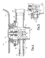
- a drain disposed for example on the bottom of a tub 11 of the type with hydromassage devices, comprises a body 12 with an outlet aperture 13 provided with a plug 14 with a shank 15 which is made to slide within a sleeve (48) supported by the body 12.
- the plug 14 is usually kept in the lowered position by its own weight, as shown in figures 2-4, so as to tightly close the outlet.
- the body 12 is provided with two bell-crank levers 16, 17, the first being integral with the drive shaft of a ratiomotor 18, the second freely hinged in a position coaxial to the first.
- the bell-crank levers 16, 17 have ends 18, 19 extending beneath the tail end of the shank 15. The other end of the lever 17 is connected, with interposition of a tightly sliding insert 21, to an emergency control rod 20.
- the end 18 is shaped from below in the form of a ring (identical to the ring configuration shown in figure 2 for the lever 16) which receives a control pin 22 of an on-off valve 23 of a duct 24 connected, by means of a pipe 27, to the discharge outlet of the hydromassage system of known technique (and consequently not shown).
- the body 12 is also provided with a fitting 25 in direct connection with the lower drain pipe 13 and connected by a duct 26 to the overflow outlet of the tub.
- the ratiomotor 18 is operatively connected to electronic control devices 49 which supply it with power to enable it 20to rotate in either direction. These control devices are not further described since they are easily imaginable by the technician.
- they can form part of the control device of the hydromassage system and therefore comprise keys on the keyboard controlling the latter.
- the lever 16 When the ratiomotor is operated in the opposite direction, the lever 16 returns to its starting position thereby lowering the plug. The movement of the lever 16 also acts upon the pin 22 which, when the lever is lowered, is pressed downwards keeping the valve 23 closed, as shown in figure 4 and, when the lever is raised, is pushed upwards opening the valve 23, as shown in figure 5.
- the emergency control rod 20 enables the drain of the bathtub to be operated even in the event of it failing to operate by means of the ratiomotor. In fact, when the control rod is pulled the lever 17, which is completely independent of the lever 16, raises the plug 14, in the same way as occurs with the lever 16, thus opening the outlet.
- levers 16 and 17 are identical even though this is obviously not strictly necessary since the lever 16 is not used as a bell-crank lever, due to the fact that the ratiomotor acts directly upon its axis of rotation.
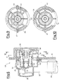
- Figures 6-10 show a device, generically indicated by reference 28, made according to further innovatory principles claimed herein, comprising the functions of delivery outlet, overflow outlet and control for operating the rod 20 of the drain described above.
- the device 28 comprises a front portion 29 protruding from a side wall inside the tub 11 and (as shown more clearly in figure 7) a portion to the rear of said wall with a fitting 32 connecting the pipe 26 to the outlet 10, a fitting 33 with two extreme positions separated by a median diaphragm 41, for a pressurized incoming water duct 34 or, alternatively 34′, and a mechanism, protected by an access cover 38, with a lever 35 connected at one end to a sliding part 36 secured to the end of the cable 20 opposite the end connected to the drain 10.
- the lever 35 is connected at the other end to a crank 37 hinged by means of a sealed pin 39 to the front part 29.
- the fitting 32 communicates with a chamber 40 in the body of the device 28, coaxial to the passage for the pin 39, which opens out, as can be seen in figure 6, into an inlet aperture 31. In this way, whenever the level of the water in the tub reaches the device 28, the excess water enters the aperture 31 and is drained off through the duct 26.
- the fitting 33 communicates on either side of the diaphragm 41, through breakable diaphragms 42, 42′, with a second chamber 43 internal and coaxial to the first chamber 40. Said second chamber 43 opens out into a delivery aperture 30.
- the fitting 33 is advantageously provided with two lateral couplings to facilitate the installation of the hydraulic system in the tub; in order to connect the incoming water pipe (34) on the left (with respect to figure 7) it is sufficient to screw it on that side to the fitting 33 and break through the communicating diaphragm 42; in order to connect the pipe (34′) on the right, it is sufficient to screw it on that side to the fitting 33 and break through the communicating diaphragm 42′.
- Rotation of the part 29 is normally prevented (as shown in figure 9) by a detent 44 on a flexible tongue 45.
- a control button 46 By pressing a control button 46 it is possible to disengage the detent 44 and then freely rotate the part 29 by hand in order to exert traction on the cable 20, by means of the pin 39, thus obtaining the manual opening of the drain 10, or the emergency opening of the drain normally operated electromechanically.
- said button can also be provided with a detent mechanism similar to the one previously described.
- the device 28 offers the advantage of comprising three elements (delivery aperture, overflow pipe, manual drain opening) in a single body, thereby making it easier to install in the tub, more compact and more attractive in appearance.
- the bodies of the devices 10 and 28 can obviously be differently shaped, also in order to obtain different aesthetic effects.
- the ratiomotor 18 can be replaced by a linear actuator such as, for example, an electromagnet, in order to act upon the end of the bell crank 16 opposite the end 18, in the same way as the action of the rod 20 on the bell crank 17.
- a linear actuator such as, for example, an electromagnet
Applications Claiming Priority (2)
| Application Number | Priority Date | Filing Date | Title |
|---|---|---|---|
| IT2187189U | 1989-10-03 | ||
| IT21871U IT218875Z2 (it) | 1989-10-03 | 1989-10-03 | Piletta di scarico, in particolare per vasca da bagno con idromassaggio |
Publications (2)
| Publication Number | Publication Date |
|---|---|
| EP0421520A2 true EP0421520A2 (fr) | 1991-04-10 |
| EP0421520A3 EP0421520A3 (en) | 1992-05-20 |
Family
ID=11188039
Family Applications (1)
| Application Number | Title | Priority Date | Filing Date |
|---|---|---|---|
| EP19900202554 Withdrawn EP0421520A3 (en) | 1989-10-03 | 1990-09-27 | Drain, in particular for bathtubs with hydromassage systems |
Country Status (2)
| Country | Link |
|---|---|
| EP (1) | EP0421520A3 (fr) |
| IT (1) | IT218875Z2 (fr) |
Cited By (12)
| Publication number | Priority date | Publication date | Assignee | Title |
|---|---|---|---|---|
| WO1992018712A1 (fr) * | 1991-04-09 | 1992-10-29 | Vico Products Mfg Co. A/S | Vidange |
| US5173973A (en) * | 1990-11-05 | 1992-12-29 | Franz-Dieter Kaldewei | Whirlpool bathtub |
| ES2063624A2 (es) * | 1992-02-18 | 1995-01-01 | Iberspa Sa | Boquilla para bañeras de hidromasaje. |
| US5386598A (en) * | 1991-09-03 | 1995-02-07 | Franz Kaldewei Gmbh & Co. | Whirlpool bathtub with devices for generating jets of water and/or air |
| NL1008037C2 (nl) * | 1998-01-15 | 1999-07-16 | Sanilux Bv | Badafvoersysteem. |
| EP1293612A1 (fr) * | 2001-09-13 | 2003-03-19 | Silfra S.P.A. | Egouttoir pour des baignoires d'hydromassage |
| EP1387013A2 (fr) * | 2002-07-31 | 2004-02-04 | Ikumi Ohta | Structure de bonde pour une baignoire |
| EP1388617A1 (fr) * | 2002-08-09 | 2004-02-11 | Franz Viegener II GmbH & Co. KG. | Garniture d'ecoulement |
| EP1388618A1 (fr) * | 2002-08-09 | 2004-02-11 | Franz Viegener II GmbH & Co. KG. | Dispositif d'écoulement |
| EP2006457A1 (fr) * | 2007-06-20 | 2008-12-24 | Jacuzzi (UK) Group plc | Valve d'écoulement mobile pour sortie d'évacuation |
| EP2169125A1 (fr) * | 2008-09-25 | 2010-03-31 | Fabrizio Nobili | Dispositif pour ouvrir un bouchon d'évier et similaire |
| JP2017075506A (ja) * | 2015-10-16 | 2017-04-20 | 丸一株式会社 | 遠隔操作式排水栓装置 |
Citations (4)
| Publication number | Priority date | Publication date | Assignee | Title |
|---|---|---|---|---|
| DE2755414B1 (de) * | 1977-12-13 | 1979-04-05 | Grohe Kg Hans | Vorrichtung zur Betaetigung des heb- und senkbaren Ventilkegels eines Wannenablaufventils |
| WO1986001100A1 (fr) * | 1984-08-08 | 1986-02-27 | Aquatech Marketing Limited | Ameliorations aux bains a jets |
| DE3507472A1 (de) * | 1985-03-02 | 1986-09-04 | Franz Kaldewei GmbH & Co, 4730 Ahlen | Whirlpool-badewanne |
| EP0312953A2 (fr) * | 1987-10-19 | 1989-04-26 | Jacuzzi Europe Spa | Dispositif de désinfection du circuit hydraulique d'un système d'hydromassage |
-
1989
- 1989-10-03 IT IT21871U patent/IT218875Z2/it active IP Right Grant
-
1990
- 1990-09-27 EP EP19900202554 patent/EP0421520A3/en not_active Withdrawn
Patent Citations (4)
| Publication number | Priority date | Publication date | Assignee | Title |
|---|---|---|---|---|
| DE2755414B1 (de) * | 1977-12-13 | 1979-04-05 | Grohe Kg Hans | Vorrichtung zur Betaetigung des heb- und senkbaren Ventilkegels eines Wannenablaufventils |
| WO1986001100A1 (fr) * | 1984-08-08 | 1986-02-27 | Aquatech Marketing Limited | Ameliorations aux bains a jets |
| DE3507472A1 (de) * | 1985-03-02 | 1986-09-04 | Franz Kaldewei GmbH & Co, 4730 Ahlen | Whirlpool-badewanne |
| EP0312953A2 (fr) * | 1987-10-19 | 1989-04-26 | Jacuzzi Europe Spa | Dispositif de désinfection du circuit hydraulique d'un système d'hydromassage |
Cited By (14)
| Publication number | Priority date | Publication date | Assignee | Title |
|---|---|---|---|---|
| US5173973A (en) * | 1990-11-05 | 1992-12-29 | Franz-Dieter Kaldewei | Whirlpool bathtub |
| WO1992018712A1 (fr) * | 1991-04-09 | 1992-10-29 | Vico Products Mfg Co. A/S | Vidange |
| US5386598A (en) * | 1991-09-03 | 1995-02-07 | Franz Kaldewei Gmbh & Co. | Whirlpool bathtub with devices for generating jets of water and/or air |
| ES2063624A2 (es) * | 1992-02-18 | 1995-01-01 | Iberspa Sa | Boquilla para bañeras de hidromasaje. |
| NL1008037C2 (nl) * | 1998-01-15 | 1999-07-16 | Sanilux Bv | Badafvoersysteem. |
| WO1999036634A1 (fr) * | 1998-01-15 | 1999-07-22 | Sanilux B.V. | Systeme de vidange de baignoire |
| EP1293612A1 (fr) * | 2001-09-13 | 2003-03-19 | Silfra S.P.A. | Egouttoir pour des baignoires d'hydromassage |
| EP1387013A2 (fr) * | 2002-07-31 | 2004-02-04 | Ikumi Ohta | Structure de bonde pour une baignoire |
| EP1387013A3 (fr) * | 2002-07-31 | 2004-11-10 | Ikumi Ohta | Structure de bonde pour une baignoire |
| EP1388617A1 (fr) * | 2002-08-09 | 2004-02-11 | Franz Viegener II GmbH & Co. KG. | Garniture d'ecoulement |
| EP1388618A1 (fr) * | 2002-08-09 | 2004-02-11 | Franz Viegener II GmbH & Co. KG. | Dispositif d'écoulement |
| EP2006457A1 (fr) * | 2007-06-20 | 2008-12-24 | Jacuzzi (UK) Group plc | Valve d'écoulement mobile pour sortie d'évacuation |
| EP2169125A1 (fr) * | 2008-09-25 | 2010-03-31 | Fabrizio Nobili | Dispositif pour ouvrir un bouchon d'évier et similaire |
| JP2017075506A (ja) * | 2015-10-16 | 2017-04-20 | 丸一株式会社 | 遠隔操作式排水栓装置 |
Also Published As
| Publication number | Publication date |
|---|---|
| IT8921871U1 (it) | 1991-04-03 |
| EP0421520A3 (en) | 1992-05-20 |
| IT8921871V0 (it) | 1989-10-03 |
| IT218875Z2 (it) | 1992-11-10 |
Similar Documents
| Publication | Publication Date | Title |
|---|---|---|
| EP0421520A2 (fr) | Drainage, spécialement pour bains avec systèmes de hydromassage | |
| US5983414A (en) | Electrical control device | |
| EP1132529A3 (fr) | Robinetterie d'écoulement d'eau | |
| US4774978A (en) | Safety mechanism for hot-water dispenser | |
| US6349921B1 (en) | Institutional flush valve operating system | |
| US6044865A (en) | Sanitary fitting in the form of a single-lever mixer tap | |
| US6123315A (en) | Apparatus and method for reducing water use | |
| US4087868A (en) | Spray apparatus for toilet | |
| JPH0886369A (ja) | 衛生機器用安全装置 | |
| WO2010067049A2 (fr) | Raccord d’évacuation amélioré | |
| KR950006323B1 (ko) | 위생 설비물용의 세정 제어 시스템 | |
| CA2107785C (fr) | Robinet de vidange | |
| US2080438A (en) | Bidet | |
| US5402541A (en) | Bathtub lifting apparatus | |
| US4138748A (en) | Hydraulic operator for water closet | |
| CN211080455U (zh) | 智能型全自动冲水马桶 | |
| JPS637791Y2 (fr) | ||
| EP1953506A1 (fr) | Système de commande électrique pour la fourniture de fluides et alimentation pour lavabo, baignoire, douche et similaires | |
| EP1293612B1 (fr) | Egouttoir pour des baignoires d'hydromassage | |
| KR200166204Y1 (ko) | 발로 개폐되는 급수장치 | |
| CN215483358U (zh) | 一种智能马桶盖及其冲洗控制装置 | |
| KR102221049B1 (ko) | 드레인 기능을 갖는 수전 박스 및 이를 활용한 수전 시스템 | |
| JPH0768713B2 (ja) | 自動水栓 | |
| JP2548044Y2 (ja) | 水抜き栓付きシャワー | |
| JP3007856B2 (ja) | 逆流防止装置 |
Legal Events
| Date | Code | Title | Description |
|---|---|---|---|
| PUAI | Public reference made under article 153(3) epc to a published international application that has entered the european phase |
Free format text: ORIGINAL CODE: 0009012 |
|
| AK | Designated contracting states |
Kind code of ref document: A2 Designated state(s): AT BE CH DE DK ES FR GB GR IT LI LU NL SE |
|
| PUAL | Search report despatched |
Free format text: ORIGINAL CODE: 0009013 |
|
| AK | Designated contracting states |
Kind code of ref document: A3 Designated state(s): AT BE CH DE DK ES FR GB GR IT LI LU NL SE |
|
| STAA | Information on the status of an ep patent application or granted ep patent |
Free format text: STATUS: THE APPLICATION IS DEEMED TO BE WITHDRAWN |
|
| 18D | Application deemed to be withdrawn |
Effective date: 19921121 |