EP0421520A2 - Drain, in particular for bathtubs with hydromassage systems - Google Patents
Drain, in particular for bathtubs with hydromassage systems Download PDFInfo
- Publication number
- EP0421520A2 EP0421520A2 EP90202554A EP90202554A EP0421520A2 EP 0421520 A2 EP0421520 A2 EP 0421520A2 EP 90202554 A EP90202554 A EP 90202554A EP 90202554 A EP90202554 A EP 90202554A EP 0421520 A2 EP0421520 A2 EP 0421520A2
- Authority
- EP
- European Patent Office
- Prior art keywords
- drain
- fact
- tub
- lever
- pipe
- Prior art date
- Legal status (The legal status is an assumption and is not a legal conclusion. Google has not performed a legal analysis and makes no representation as to the accuracy of the status listed.)
- Withdrawn
Links
Images


Classifications
-
- E—FIXED CONSTRUCTIONS
- E03—WATER SUPPLY; SEWERAGE
- E03C—DOMESTIC PLUMBING INSTALLATIONS FOR FRESH WATER OR WASTE WATER; SINKS
- E03C1/00—Domestic plumbing installations for fresh water or waste water; Sinks
- E03C1/12—Plumbing installations for waste water; Basins or fountains connected thereto; Sinks
- E03C1/22—Outlet devices mounted in basins, baths, or sinks
- E03C1/23—Outlet devices mounted in basins, baths, or sinks with mechanical closure mechanisms
- E03C1/2302—Outlet devices mounted in basins, baths, or sinks with mechanical closure mechanisms the actuation force being transmitted to the plug via rigid elements
-
- E—FIXED CONSTRUCTIONS
- E03—WATER SUPPLY; SEWERAGE
- E03C—DOMESTIC PLUMBING INSTALLATIONS FOR FRESH WATER OR WASTE WATER; SINKS
- E03C1/00—Domestic plumbing installations for fresh water or waste water; Sinks
- E03C1/12—Plumbing installations for waste water; Basins or fountains connected thereto; Sinks
- E03C1/22—Outlet devices mounted in basins, baths, or sinks
- E03C1/23—Outlet devices mounted in basins, baths, or sinks with mechanical closure mechanisms
Definitions
- This invention refers to an improved drain for sanitary appliances, in particular for bathtubs for example with a built-in hydromassage system, and to a water delivery device, overflow pipe inlet, and manual operation of said drain.
- the general scope of this invention is to obviate the aforementioned problems by providing a drain, in particular for bathtubs with a built-in hydromassage system, which comprises the function of emptying the hydromassage system whenever the drain is operated to empty the bathtub.
- a further scope is to provide a device for manually operating said drain which also comprises the functions of a delivery aperture and an overflow outlet.
- a drain for sanitary fittings in particular for bathtubs with a built-in hydromassage system, of the type having a plug, with a shank extending downwards inside the drain, which is raised by thrust means which exert pressure on said shank to connect the bottom of the tub to a drain pipe, characterized by the fact of comprising a valve for opening a discharge passage between the hydromassage system and said drain pipe, the valve being made to open by said thrust means when the plug is made to rise.
- a drain disposed for example on the bottom of a tub 11 of the type with hydromassage devices, comprises a body 12 with an outlet aperture 13 provided with a plug 14 with a shank 15 which is made to slide within a sleeve (48) supported by the body 12.
- the plug 14 is usually kept in the lowered position by its own weight, as shown in figures 2-4, so as to tightly close the outlet.
- the body 12 is provided with two bell-crank levers 16, 17, the first being integral with the drive shaft of a ratiomotor 18, the second freely hinged in a position coaxial to the first.
- the bell-crank levers 16, 17 have ends 18, 19 extending beneath the tail end of the shank 15. The other end of the lever 17 is connected, with interposition of a tightly sliding insert 21, to an emergency control rod 20.
- the end 18 is shaped from below in the form of a ring (identical to the ring configuration shown in figure 2 for the lever 16) which receives a control pin 22 of an on-off valve 23 of a duct 24 connected, by means of a pipe 27, to the discharge outlet of the hydromassage system of known technique (and consequently not shown).
- the body 12 is also provided with a fitting 25 in direct connection with the lower drain pipe 13 and connected by a duct 26 to the overflow outlet of the tub.
- the ratiomotor 18 is operatively connected to electronic control devices 49 which supply it with power to enable it 20to rotate in either direction. These control devices are not further described since they are easily imaginable by the technician.
- they can form part of the control device of the hydromassage system and therefore comprise keys on the keyboard controlling the latter.
- the lever 16 When the ratiomotor is operated in the opposite direction, the lever 16 returns to its starting position thereby lowering the plug. The movement of the lever 16 also acts upon the pin 22 which, when the lever is lowered, is pressed downwards keeping the valve 23 closed, as shown in figure 4 and, when the lever is raised, is pushed upwards opening the valve 23, as shown in figure 5.
- the emergency control rod 20 enables the drain of the bathtub to be operated even in the event of it failing to operate by means of the ratiomotor. In fact, when the control rod is pulled the lever 17, which is completely independent of the lever 16, raises the plug 14, in the same way as occurs with the lever 16, thus opening the outlet.
- levers 16 and 17 are identical even though this is obviously not strictly necessary since the lever 16 is not used as a bell-crank lever, due to the fact that the ratiomotor acts directly upon its axis of rotation.
- Figures 6-10 show a device, generically indicated by reference 28, made according to further innovatory principles claimed herein, comprising the functions of delivery outlet, overflow outlet and control for operating the rod 20 of the drain described above.
- the device 28 comprises a front portion 29 protruding from a side wall inside the tub 11 and (as shown more clearly in figure 7) a portion to the rear of said wall with a fitting 32 connecting the pipe 26 to the outlet 10, a fitting 33 with two extreme positions separated by a median diaphragm 41, for a pressurized incoming water duct 34 or, alternatively 34′, and a mechanism, protected by an access cover 38, with a lever 35 connected at one end to a sliding part 36 secured to the end of the cable 20 opposite the end connected to the drain 10.
- the lever 35 is connected at the other end to a crank 37 hinged by means of a sealed pin 39 to the front part 29.
- the fitting 32 communicates with a chamber 40 in the body of the device 28, coaxial to the passage for the pin 39, which opens out, as can be seen in figure 6, into an inlet aperture 31. In this way, whenever the level of the water in the tub reaches the device 28, the excess water enters the aperture 31 and is drained off through the duct 26.
- the fitting 33 communicates on either side of the diaphragm 41, through breakable diaphragms 42, 42′, with a second chamber 43 internal and coaxial to the first chamber 40. Said second chamber 43 opens out into a delivery aperture 30.
- the fitting 33 is advantageously provided with two lateral couplings to facilitate the installation of the hydraulic system in the tub; in order to connect the incoming water pipe (34) on the left (with respect to figure 7) it is sufficient to screw it on that side to the fitting 33 and break through the communicating diaphragm 42; in order to connect the pipe (34′) on the right, it is sufficient to screw it on that side to the fitting 33 and break through the communicating diaphragm 42′.
- Rotation of the part 29 is normally prevented (as shown in figure 9) by a detent 44 on a flexible tongue 45.
- a control button 46 By pressing a control button 46 it is possible to disengage the detent 44 and then freely rotate the part 29 by hand in order to exert traction on the cable 20, by means of the pin 39, thus obtaining the manual opening of the drain 10, or the emergency opening of the drain normally operated electromechanically.
- said button can also be provided with a detent mechanism similar to the one previously described.
- the device 28 offers the advantage of comprising three elements (delivery aperture, overflow pipe, manual drain opening) in a single body, thereby making it easier to install in the tub, more compact and more attractive in appearance.
- the bodies of the devices 10 and 28 can obviously be differently shaped, also in order to obtain different aesthetic effects.
- the ratiomotor 18 can be replaced by a linear actuator such as, for example, an electromagnet, in order to act upon the end of the bell crank 16 opposite the end 18, in the same way as the action of the rod 20 on the bell crank 17.
- a linear actuator such as, for example, an electromagnet
Abstract
A drain (10) for sanitary appliances, in particular for bathtubs with a built-in hydromassage system, comprises a plug with a shank (15) extending downwards inside the drain (10) to enable it to be raised by first (16) or second (17) thrust means and thus connect the bottom of the tub (11) to a drain pipe (13). The first means (16) being controlled by an electric ratiomotor (18) and the second means (17) being controlled by a hand-operated rod (20).
The first and second means (16, 17) also control a valve (23) which opens a passage (24) between the hydromassage system and said drain pipe (13).
Description
- This invention refers to an improved drain for sanitary appliances, in particular for bathtubs for example with a built-in hydromassage system, and to a water delivery device, overflow pipe inlet, and manual operation of said drain.
- There are, in bathtubs having a built-in hydromassage system, known devices for emptying out the hydromassage system at the end of the cycle in order to prevent stagnation of water which could result in obvious hygiene problems. In the known technique, the operation of emptying out the hydromassage system, by means of the aforesaid device, and the operation of emptying out the bath, by operating the drain, are carried out separately and the task of carrying out both these operations in sequence is entrusted either to the diligence of the user or to the synchronization of the individual emptying and draining devices by the hydromassage control circuit. Consequently, there is always a possibility that due to the forgetfulness of the user or due to failure of the control circuit to operate properly, the water in the hydromassage system is not drained off. Moreover, the existence of separate mechanisms gives rise to problems of size and cost.
- The general scope of this invention is to obviate the aforementioned problems by providing a drain, in particular for bathtubs with a built-in hydromassage system, which comprises the function of emptying the hydromassage system whenever the drain is operated to empty the bathtub. A further scope is to provide a device for manually operating said drain which also comprises the functions of a delivery aperture and an overflow outlet. This scope is achieved according to the invention by providing a drain for sanitary fittings, in particular for bathtubs with a built-in hydromassage system, of the type having a plug, with a shank extending downwards inside the drain, which is raised by thrust means which exert pressure on said shank to connect the bottom of the tub to a drain pipe, characterized by the fact of comprising a valve for opening a discharge passage between the hydromassage system and said drain pipe, the valve being made to open by said thrust means when the plug is made to rise.
- The innovatory principles of this invention and its advantages with respect to the known technique will be more clearly evident from the following description of a possible exemplificative embodiment applying such principles, with reference to the accompanying figures, in which:
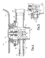
- - figure 1 shows a partial cutaway plan view along the line I-I of figure 2 of a drain made according to this invention;
- - figure 2 shows a partial cutaway side view along the line II-II of figure 1;
- - figure 3 shows a partial cutaway side view along the line III-III of figure 1;
- - figure 4 shows a partial cutaway side view along the line IV-IV of figure 1;
- - figure 5 shows a partial cutaway view of a part of figure 4 in a different operating position;
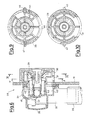
- - figure 6 shows a partial cutaway side view along the line VI-VI of figure 7 of a delivery aperture, overflow pipe and emergency control mechanism for the drain of figures 1-5;
- - figure 7 shows a partial cutaway rear view along the line VII-VII of figure 8;
- - figure 8 shows a partial cutaway view along the line VIII-VIII of figure 7;
- - figure 9 shows a cutaway view along the line IX-IX of figure 6;
- - figure 10 shows a cutaway view along the line X-X of figure 6.
- With reference to the figures, a drain, generically indicated by
reference 10 in figures 1-4, disposed for example on the bottom of atub 11 of the type with hydromassage devices, comprises abody 12 with anoutlet aperture 13 provided with aplug 14 with ashank 15 which is made to slide within a sleeve (48) supported by thebody 12. Theplug 14 is usually kept in the lowered position by its own weight, as shown in figures 2-4, so as to tightly close the outlet. - To lift the
plug 14, thebody 12 is provided with two bell-crank levers 16, 17, the first being integral with the drive shaft of aratiomotor 18, the second freely hinged in a position coaxial to the first. - The bell-crank levers 16, 17 have
ends lever 17 is connected, with interposition of a tightly slidinginsert 21, to anemergency control rod 20. - According to the innovatory principles claimed herein, the
end 18 is shaped from below in the form of a ring (identical to the ring configuration shown in figure 2 for the lever 16) which receives acontrol pin 22 of an on-offvalve 23 of aduct 24 connected, by means of apipe 27, to the discharge outlet of the hydromassage system of known technique (and consequently not shown). - The
body 12 is also provided with afitting 25 in direct connection with thelower drain pipe 13 and connected by aduct 26 to the overflow outlet of the tub. - The
ratiomotor 18 is operatively connected toelectronic control devices 49 which supply it with power to enable it 20to rotate in either direction. These control devices are not further described since they are easily imaginable by the technician. - For example, they can form part of the control device of the hydromassage system and therefore comprise keys on the keyboard controlling the latter.
- When the ratiomotor is operated in a clockwise direction (as shown in figure 2), the
lever 16 rotates towards the position indicated by the broken line in figure 2 so as to raise the plug by pressing on itsshank 15. - When the ratiomotor is operated in the opposite direction, the
lever 16 returns to its starting position thereby lowering the plug. The movement of thelever 16 also acts upon thepin 22 which, when the lever is lowered, is pressed downwards keeping thevalve 23 closed, as shown in figure 4 and, when the lever is raised, is pushed upwards opening thevalve 23, as shown in figure 5. - Thus the emptying of the bathtub through the
drain pipe 13 coincides with the emptying of the hydromasseage system, so as to prevent water from accumulating in its pipes. Theemergency control rod 20 enables the drain of the bathtub to be operated even in the event of it failing to operate by means of the ratiomotor. In fact, when the control rod is pulled thelever 17, which is completely independent of thelever 16, raises theplug 14, in the same way as occurs with thelever 16, thus opening the outlet. - Even though the described drain is advantageously provided with an electromechanically-operated aperture, a drain applying the innovatory principles of this invention which simply has a manual control is easily imaginable. For this purpose, it is sufficient to manufacture a drain as described above but without the
lever 16 and theratiomotor 18, while thepin 22 is extended to fit into the end ring of thelever 17, so that thedischarge valve 23 is operated by the movement of thelever 17 as described above for the movement of thelever 16. - Moreover, it is considered advantageously preferable not to operate the hydromassage outlet by means of the emergency lever, so as to prevent any impediment in the action of the lever connected to the ratiomotor from also affecting the emergency mechanism: It is, however, conceivable to make the
pin 22 longer so as to enable it to be operated also by the emergency lever. - From the foregoing description the technician can easily imagine how it is possible to make motor-operated or manually-operated drains as simple variations of one another so as to minimize production costs, while maintaining many of the component parts of the two embodiments unchanged.
- For the same reason, the
levers lever 16 is not used as a bell-crank lever, due to the fact that the ratiomotor acts directly upon its axis of rotation. - Figures 6-10 show a device, generically indicated by
reference 28, made according to further innovatory principles claimed herein, comprising the functions of delivery outlet, overflow outlet and control for operating therod 20 of the drain described above. - As can be seen for example in figure 6, the
device 28 comprises afront portion 29 protruding from a side wall inside thetub 11 and (as shown more clearly in figure 7) a portion to the rear of said wall with afitting 32 connecting thepipe 26 to theoutlet 10, afitting 33 with two extreme positions separated by amedian diaphragm 41, for a pressurizedincoming water duct 34 or, alternatively 34′, and a mechanism, protected by anaccess cover 38, with alever 35 connected at one end to asliding part 36 secured to the end of thecable 20 opposite the end connected to thedrain 10. - As can also be seen in figure 8, the
lever 35 is connected at the other end to acrank 37 hinged by means of a sealedpin 39 to thefront part 29. - As is also shown in figure 8, the
fitting 32 communicates with achamber 40 in the body of thedevice 28, coaxial to the passage for thepin 39, which opens out, as can be seen in figure 6, into aninlet aperture 31. In this way, whenever the level of the water in the tub reaches thedevice 28, the excess water enters theaperture 31 and is drained off through theduct 26. - The fitting 33 communicates on either side of the
diaphragm 41, throughbreakable diaphragms second chamber 43 internal and coaxial to thefirst chamber 40. Saidsecond chamber 43 opens out into adelivery aperture 30. Thefitting 33 is advantageously provided with two lateral couplings to facilitate the installation of the hydraulic system in the tub; in order to connect the incoming water pipe (34) on the left (with respect to figure 7) it is sufficient to screw it on that side to thefitting 33 and break through the communicatingdiaphragm 42; in order to connect the pipe (34′) on the right, it is sufficient to screw it on that side to thefitting 33 and break through the communicatingdiaphragm 42′. - It shold be noted that the paths between the
fitting 33 and theaperture 30 and between thefitting 32 and theaperture 31 are completely separate inside the body of thedevice 28. - Rotation of the
part 29 is normally prevented (as shown in figure 9) by a detent 44 on aflexible tongue 45. By pressing acontrol button 46 it is possible to disengage thedetent 44 and then freely rotate thepart 29 by hand in order to exert traction on thecable 20, by means of thepin 39, thus obtaining the manual opening of thedrain 10, or the emergency opening of the drain normally operated electromechanically. - The presence of a detent 44 enseures that the rod controlling the opening of the drain is only operated intentionally.
- In order to give the part 29 a symmetrical appearance, it is advantageously provided with a second
non-operative button 47. - It is obvious however that said button can also be provided with a detent mechanism similar to the one previously described.
- The
device 28 offers the advantage of comprising three elements (delivery aperture, overflow pipe, manual drain opening) in a single body, thereby making it easier to install in the tub, more compact and more attractive in appearance. - The foregoing description of the devices according to the invention is obviously given by way of example in order to illustrate the innovatory principles of the invention and should not therefore be considered as a limitation to the sphere of the invention claimed herein.
- For example, the bodies of the
devices - The
ratiomotor 18 can be replaced by a linear actuator such as, for example, an electromagnet, in order to act upon the end of thebell crank 16 opposite theend 18, in the same way as the action of therod 20 on thebell crank 17.
Claims (10)
1. Drain for sanitary fittings, in particular for bathtubs with a built-in hydromassage system, of the type having a plug, with a shank extending downwards inside the drain, which is raised by thrust means which exert pressure on said shank to connect the bottom of the tub to a drain pipe, characterized by the fact of comprising a valve for opening a discharge passage between the hydromassage system and said drain pipe, the valve being made to open by said thrust means when the plug is made to rise.
2. Drain as claimed in Claim 1, characterized by the fact that said thrust means comprise a lever with a first substantially horizontal arm disposed with its free end beneath said shank and with means for controlling the rotation of the lever in order to exert pressure on the shank to raise the plug, the valve being composed of a flap hinged from above and movable from a lowered position in which it tightly closed said passage to a raised position in which it opens said passage, an actuating pin protrudes from said flap and fits into a housing in said free end of the first arm so as to be pressed downwards, in the position in which it closes the valve, by said free end when the lever is in the rest position and to be raised, in the position in which it opens the valve, by said free end when the lever is in the rotated position in which it raises the plug.
3. Drain as claimed in Claim 2, characterized by the fact that the control means comprise a rod connected to the other end of the lever, shaped at right angles with the second arm directed substantially upwards, to enable it to rotate around a median pin, in order to raise the plug when traction is exerted on the rod.
4. Drain as claimed in Claim 2, characterized by the fact that the control means comprise a ratiomotor with its drive shaft carrying said lever hinged to it.
5. Drain as claimed in Claim 1, characterized by the fact that it is connected, in direct communication with said drain pipe, to a pipe connected to an overflow aperture in the tub.
6. Drain as claimed in Claim 3, comprising a hand-operated device of the type comprising a body passing through a lateral wall of the tub and composed of a first fixed portion to the rear of said wall and concealed from view and of a second operative portion, protruding in front from said wall towards the inside of the tub, movable with respect to the first portion and connected to said rod by a mechanism to enable it to be pulled by hand, characterized by the fact that said second portion is rotatable around a pin perpendicular to the wall and ending in the first portion with a crank connected to the rod to form said mechanism, so as to operate it when the second portion is rotated by hand.
7. Drain as claimed in Claim 6, characterized by the fact that said body internally comprises a first duct with one end connected on said first portion to a water delivery pipe and the other end open in said second portion to send water into the tub.
8. Drain as claimed in Claim 6, characterized by the fact that said body internally comprises a second duct with one end connected on said first portion tg a pipe leading into the drain pipe and the other end open in said second portion to allow water to enter from the tub whenever the level of the water in the tub reaches the operating device in order to constitute the overflow pipe of the tub.
9. Drain as claimed in Claim 6, characterized by the fact that said second portion comprises removable locking means for preventing rotation.
10. Drain as claimed in Claim 9, characterized by the fact that the removable locking means for preventing rotation comprise a button protruding from the lateral surface of said second portion and elastically movable towards the inside to disengage a detent from a complementary housing inside said second portion.
Applications Claiming Priority (2)
| Application Number | Priority Date | Filing Date | Title |
|---|---|---|---|
| IT2187189U | 1989-10-03 | ||
| IT21871U IT218875Z2 (en) | 1989-10-03 | 1989-10-03 | DISCHARGE WASTE, IN PARTICULAR FOR BATHTUB WITH WHIRLPOOL |
Publications (2)
| Publication Number | Publication Date |
|---|---|
| EP0421520A2 true EP0421520A2 (en) | 1991-04-10 |
| EP0421520A3 EP0421520A3 (en) | 1992-05-20 |
Family
ID=11188039
Family Applications (1)
| Application Number | Title | Priority Date | Filing Date |
|---|---|---|---|
| EP19900202554 Withdrawn EP0421520A3 (en) | 1989-10-03 | 1990-09-27 | Drain, in particular for bathtubs with hydromassage systems |
Country Status (2)
| Country | Link |
|---|---|
| EP (1) | EP0421520A3 (en) |
| IT (1) | IT218875Z2 (en) |
Cited By (12)
| Publication number | Priority date | Publication date | Assignee | Title |
|---|---|---|---|---|
| WO1992018712A1 (en) * | 1991-04-09 | 1992-10-29 | Vico Products Mfg Co. A/S | Drain valve |
| US5173973A (en) * | 1990-11-05 | 1992-12-29 | Franz-Dieter Kaldewei | Whirlpool bathtub |
| ES2063624A2 (en) * | 1992-02-18 | 1995-01-01 | Iberspa Sa | Opening for hydromassage baths |
| US5386598A (en) * | 1991-09-03 | 1995-02-07 | Franz Kaldewei Gmbh & Co. | Whirlpool bathtub with devices for generating jets of water and/or air |
| NL1008037C2 (en) * | 1998-01-15 | 1999-07-16 | Sanilux Bv | Bath drain system. |
| EP1293612A1 (en) * | 2001-09-13 | 2003-03-19 | Silfra S.P.A. | Water discharging device for hydromassaging tubs |
| EP1387013A2 (en) * | 2002-07-31 | 2004-02-04 | Ikumi Ohta | Drain plug structure for bath tub |
| EP1388617A1 (en) * | 2002-08-09 | 2004-02-11 | Franz Viegener II GmbH & Co. KG. | Outlet fitting |
| EP1388618A1 (en) * | 2002-08-09 | 2004-02-11 | Franz Viegener II GmbH & Co. KG. | Outlet device |
| EP2006457A1 (en) * | 2007-06-20 | 2008-12-24 | Jacuzzi (UK) Group plc | Movable drain valve for a drain outlet |
| EP2169125A1 (en) * | 2008-09-25 | 2010-03-31 | Fabrizio Nobili | Device for opening a plug for sink and the like |
| JP2017075506A (en) * | 2015-10-16 | 2017-04-20 | 丸一株式会社 | Remote-controlled drain plug device |
Citations (4)
| Publication number | Priority date | Publication date | Assignee | Title |
|---|---|---|---|---|
| DE2755414B1 (en) * | 1977-12-13 | 1979-04-05 | Grohe Kg Hans | Device for actuating the liftable and lowerable valve cone of a bathtub drain valve |
| WO1986001100A1 (en) * | 1984-08-08 | 1986-02-27 | Aquatech Marketing Limited | Improvements relating to spas or whirlpool baths |
| DE3507472A1 (en) * | 1985-03-02 | 1986-09-04 | Franz Kaldewei GmbH & Co, 4730 Ahlen | Whirlpool bathtub |
| EP0312953A2 (en) * | 1987-10-19 | 1989-04-26 | Jacuzzi Europe Spa | Disinfection assembly for the hydraulic circuit of a hydromassage system |
-
1989
- 1989-10-03 IT IT21871U patent/IT218875Z2/en active IP Right Grant
-
1990
- 1990-09-27 EP EP19900202554 patent/EP0421520A3/en not_active Withdrawn
Patent Citations (4)
| Publication number | Priority date | Publication date | Assignee | Title |
|---|---|---|---|---|
| DE2755414B1 (en) * | 1977-12-13 | 1979-04-05 | Grohe Kg Hans | Device for actuating the liftable and lowerable valve cone of a bathtub drain valve |
| WO1986001100A1 (en) * | 1984-08-08 | 1986-02-27 | Aquatech Marketing Limited | Improvements relating to spas or whirlpool baths |
| DE3507472A1 (en) * | 1985-03-02 | 1986-09-04 | Franz Kaldewei GmbH & Co, 4730 Ahlen | Whirlpool bathtub |
| EP0312953A2 (en) * | 1987-10-19 | 1989-04-26 | Jacuzzi Europe Spa | Disinfection assembly for the hydraulic circuit of a hydromassage system |
Cited By (14)
| Publication number | Priority date | Publication date | Assignee | Title |
|---|---|---|---|---|
| US5173973A (en) * | 1990-11-05 | 1992-12-29 | Franz-Dieter Kaldewei | Whirlpool bathtub |
| WO1992018712A1 (en) * | 1991-04-09 | 1992-10-29 | Vico Products Mfg Co. A/S | Drain valve |
| US5386598A (en) * | 1991-09-03 | 1995-02-07 | Franz Kaldewei Gmbh & Co. | Whirlpool bathtub with devices for generating jets of water and/or air |
| ES2063624A2 (en) * | 1992-02-18 | 1995-01-01 | Iberspa Sa | Opening for hydromassage baths |
| NL1008037C2 (en) * | 1998-01-15 | 1999-07-16 | Sanilux Bv | Bath drain system. |
| WO1999036634A1 (en) * | 1998-01-15 | 1999-07-22 | Sanilux B.V. | Bath drainage system |
| EP1293612A1 (en) * | 2001-09-13 | 2003-03-19 | Silfra S.P.A. | Water discharging device for hydromassaging tubs |
| EP1387013A2 (en) * | 2002-07-31 | 2004-02-04 | Ikumi Ohta | Drain plug structure for bath tub |
| EP1387013A3 (en) * | 2002-07-31 | 2004-11-10 | Ikumi Ohta | Drain plug structure for bath tub |
| EP1388617A1 (en) * | 2002-08-09 | 2004-02-11 | Franz Viegener II GmbH & Co. KG. | Outlet fitting |
| EP1388618A1 (en) * | 2002-08-09 | 2004-02-11 | Franz Viegener II GmbH & Co. KG. | Outlet device |
| EP2006457A1 (en) * | 2007-06-20 | 2008-12-24 | Jacuzzi (UK) Group plc | Movable drain valve for a drain outlet |
| EP2169125A1 (en) * | 2008-09-25 | 2010-03-31 | Fabrizio Nobili | Device for opening a plug for sink and the like |
| JP2017075506A (en) * | 2015-10-16 | 2017-04-20 | 丸一株式会社 | Remote-controlled drain plug device |
Also Published As
| Publication number | Publication date |
|---|---|
| IT8921871V0 (en) | 1989-10-03 |
| EP0421520A3 (en) | 1992-05-20 |
| IT8921871U1 (en) | 1991-04-03 |
| IT218875Z2 (en) | 1992-11-10 |
Similar Documents
| Publication | Publication Date | Title |
|---|---|---|
| EP0421520A2 (en) | Drain, in particular for bathtubs with hydromassage systems | |
| EP1132529A3 (en) | Water outlet fitting | |
| US6047417A (en) | Cabinet door operated faucet valve | |
| US6349921B1 (en) | Institutional flush valve operating system | |
| US6044865A (en) | Sanitary fitting in the form of a single-lever mixer tap | |
| US6123315A (en) | Apparatus and method for reducing water use | |
| US4087868A (en) | Spray apparatus for toilet | |
| JPH0886369A (en) | Safety device for sanitary equipment | |
| WO2010067049A2 (en) | Improved waste fitting | |
| KR950006323B1 (en) | Flush control system for plumbing fixture | |
| CA2107785C (en) | Drain valve | |
| US2080438A (en) | Bidet | |
| US5402541A (en) | Bathtub lifting apparatus | |
| US4138748A (en) | Hydraulic operator for water closet | |
| CN211080455U (en) | Intelligent full-automatic flushing toilet | |
| JPS637791Y2 (en) | ||
| EP1953506A1 (en) | Electronic control system for fluid delivery and supply for sink, bathtub, shower and the like | |
| EP1293612B1 (en) | Water discharging device for hydromassaging tubs | |
| KR200166204Y1 (en) | Water supply device switched feet | |
| CN215483358U (en) | Intelligent toilet lid and flushing control device thereof | |
| CN108458135B (en) | Pull-out faucet waterway switching control mechanism | |
| KR102221049B1 (en) | Faucet control box having drain function and faucet system thereby | |
| JPH0768713B2 (en) | Automatic faucet | |
| JP2548044Y2 (en) | Shower with drain cock | |
| CA1079002A (en) | Hydraulic operator for water closet |
Legal Events
| Date | Code | Title | Description |
|---|---|---|---|
| PUAI | Public reference made under article 153(3) epc to a published international application that has entered the european phase |
Free format text: ORIGINAL CODE: 0009012 |
|
| AK | Designated contracting states |
Kind code of ref document: A2 Designated state(s): AT BE CH DE DK ES FR GB GR IT LI LU NL SE |
|
| PUAL | Search report despatched |
Free format text: ORIGINAL CODE: 0009013 |
|
| AK | Designated contracting states |
Kind code of ref document: A3 Designated state(s): AT BE CH DE DK ES FR GB GR IT LI LU NL SE |
|
| STAA | Information on the status of an ep patent application or granted ep patent |
Free format text: STATUS: THE APPLICATION IS DEEMED TO BE WITHDRAWN |
|
| 18D | Application deemed to be withdrawn |
Effective date: 19921121 |