EP0420554A1 - Kontrolldämpfer für Strahlungsofen - Google Patents
Kontrolldämpfer für Strahlungsofen Download PDFInfo
- Publication number
- EP0420554A1 EP0420554A1 EP90310436A EP90310436A EP0420554A1 EP 0420554 A1 EP0420554 A1 EP 0420554A1 EP 90310436 A EP90310436 A EP 90310436A EP 90310436 A EP90310436 A EP 90310436A EP 0420554 A1 EP0420554 A1 EP 0420554A1
- Authority
- EP
- European Patent Office
- Prior art keywords
- wall
- air
- heated air
- oven
- apertures
- Prior art date
- Legal status (The legal status is an assumption and is not a legal conclusion. Google has not performed a legal analysis and makes no representation as to the accuracy of the status listed.)
- Granted
Links
- 238000001035 drying Methods 0.000 claims abstract description 37
- 238000010438 heat treatment Methods 0.000 claims description 24
- 230000005855 radiation Effects 0.000 claims description 13
- 230000001276 controlling effect Effects 0.000 claims description 8
- 230000001105 regulatory effect Effects 0.000 claims description 5
- 238000000034 method Methods 0.000 claims description 4
- 230000003134 recirculating effect Effects 0.000 claims description 4
- 238000007664 blowing Methods 0.000 claims 1
- 239000011248 coating agent Substances 0.000 description 6
- 238000000576 coating method Methods 0.000 description 6
- 238000002485 combustion reaction Methods 0.000 description 4
- 230000004907 flux Effects 0.000 description 4
- 230000002411 adverse Effects 0.000 description 3
- 230000000694 effects Effects 0.000 description 3
- CURLTUGMZLYLDI-UHFFFAOYSA-N Carbon dioxide Chemical compound O=C=O CURLTUGMZLYLDI-UHFFFAOYSA-N 0.000 description 2
- 230000000903 blocking effect Effects 0.000 description 2
- 238000010586 diagram Methods 0.000 description 2
- VNWKTOKETHGBQD-UHFFFAOYSA-N methane Chemical compound C VNWKTOKETHGBQD-UHFFFAOYSA-N 0.000 description 2
- 230000037303 wrinkles Effects 0.000 description 2
- UGFAIRIUMAVXCW-UHFFFAOYSA-N Carbon monoxide Chemical compound [O+]#[C-] UGFAIRIUMAVXCW-UHFFFAOYSA-N 0.000 description 1
- QVGXLLKOCUKJST-UHFFFAOYSA-N atomic oxygen Chemical compound [O] QVGXLLKOCUKJST-UHFFFAOYSA-N 0.000 description 1
- 238000010923 batch production Methods 0.000 description 1
- 229910002092 carbon dioxide Inorganic materials 0.000 description 1
- 239000001569 carbon dioxide Substances 0.000 description 1
- 229910002091 carbon monoxide Inorganic materials 0.000 description 1
- 239000003245 coal Substances 0.000 description 1
- 238000004891 communication Methods 0.000 description 1
- 238000010924 continuous production Methods 0.000 description 1
- 239000000428 dust Substances 0.000 description 1
- 230000001788 irregular Effects 0.000 description 1
- 239000007788 liquid Substances 0.000 description 1
- 238000012423 maintenance Methods 0.000 description 1
- 238000004519 manufacturing process Methods 0.000 description 1
- 239000003345 natural gas Substances 0.000 description 1
- 229910052760 oxygen Inorganic materials 0.000 description 1
- 239000001301 oxygen Substances 0.000 description 1
- 239000007787 solid Substances 0.000 description 1
- 238000001228 spectrum Methods 0.000 description 1
- 239000000126 substance Substances 0.000 description 1
- 239000002918 waste heat Substances 0.000 description 1
Images


Classifications
-
- F—MECHANICAL ENGINEERING; LIGHTING; HEATING; WEAPONS; BLASTING
- F26—DRYING
- F26B—DRYING SOLID MATERIALS OR OBJECTS BY REMOVING LIQUID THEREFROM
- F26B3/00—Drying solid materials or objects by processes involving the application of heat
- F26B3/28—Drying solid materials or objects by processes involving the application of heat by radiation, e.g. from the sun
- F26B3/30—Drying solid materials or objects by processes involving the application of heat by radiation, e.g. from the sun from infrared-emitting elements
- F26B3/305—Drying solid materials or objects by processes involving the application of heat by radiation, e.g. from the sun from infrared-emitting elements the infrared radiation being generated by combustion or combustion gases
-
- F—MECHANICAL ENGINEERING; LIGHTING; HEATING; WEAPONS; BLASTING
- F26—DRYING
- F26B—DRYING SOLID MATERIALS OR OBJECTS BY REMOVING LIQUID THEREFROM
- F26B2210/00—Drying processes and machines for solid objects characterised by the specific requirements of the drying good
- F26B2210/12—Vehicle bodies, e.g. after being painted
Definitions
- This invention relates to a radiant oven for drying objects and is more particularly concerned with control dampers that can modify the amount of radiant energy emitted by selected portions of a radiating wall of the radiant oven.
- Radiant energy resulting from infrared emission by radiating surfaces has long been used to dry or cure coated objects.
- Heat energy transferred to a radiating surface by convective, contact, or radiative heating can in turn be radiatively transferred to the coating of an object, speeding the natural drying process that hardens the coating on that object.
- An example of convective transfer of heat to a radiating surface for the purpose of drying coated objects is found in Best, U.S. Pat. 4,546,553 in which opposed curved walls direct infrared radiant heat against painted objects passed through an oven chamber. The walls of the oven chamber are heated by directing turbulent air against the inside surfaces of the curved wall, causing the curved walls to heat and thereby radiate increased amounts of infrared heat into the oven chamber.
- This apparatus has the disadvantage in that the surfaces of objects placed within the oven chamber differentially heat up to a desired temperature because each area of the object generally receives a varying amount of incident infrared energy according to its particular distance and its surface orientation in relation to the radiating wall. The coating on the object is therefore heated at different rates, adversely affecting the drying process.
- Best '552 additionally controls the equilibrium temperature of the surface of an object in an oven chamber through the use of induced air movement within the oven chamber. Air having a lower temperature than the temperature of the curved walls of the oven chamber is circulated in a desired direction through the oven chamber to cool selected portions of the object so that the temperature of the object remains constant at all points on its surface, ensuring the even drying of the coating on the object.
- Air having a lower temperature than the temperature of the curved walls of the oven chamber is circulated in a desired direction through the oven chamber to cool selected portions of the object so that the temperature of the object remains constant at all points on its surface, ensuring the even drying of the coating on the object.
- such an apparatus for controlling the temperature of the object often requires highly filtered air, precise positioning of multiple blowers to circulate air and a detailed knowledge of the amount of convective transfer of heat from the object to the cooler air.
- Yet another object of this invention is to provide an apparatus having one or more control dampers which regulate the amount of heated air contacting an absorbing surface of a radiant wall of a radiant wall drying oven.
- this invention comprises a radiant wall drying oven that includes a first wall and a second wall situated in spaced apart relation to define an air conducting passageway. Heated air is supplied to contact the first wall, and a selected amount of heated air is allowed to pass through inlets into the air conducting passageway. Valves, positioned at a predetermined site relative to the second wall, control the amount of heated air contacting a portion of the second wall. Since the temperature of that portion of the second wall controls the amount of radiant heat emitted by that area of the second wall, the amount of radiant heat directed against the object is regulated.
- the second wall at least partially defines a drying chamber into which objects can be individually placed in a batch process, or may be alternatively conveyed by a conveyor in a continuous process.
- the drying chamber can be pneumatically sealed to prevent the introduction of dust, moisture, or other substances that can detrimentally affect the drying or curing process.
- Heated air can be supplied to contact the first wall by the combination of a heater for heating air, a blower for propelling the heated air toward the first wall, and a first conduit for channelling the heated and blown air to contact the first wall.
- the heater can be any device that acts to heat air to a desired temperature, and may be gas-fired or oil-fired.
- a blower suitable for impelling the heated air into the first conduit can be a propellor or other type fan.
- Air inlets may constitute apertures defined within the first wall at predetermined sites. Heated air blown by a fan or other impellor through the first conduit contacts the first wall and may only enter the air passageway defined by the space between the first and second walls through these apertures. As a consequence, those portions of the second wall that are initially contacted by the heated air passing through the apertures will be most strongly heated, and consequently radiate increased amounts of infrared heat relative to those portions of the second wall that are not initially contacted by the heated air flow.
- Heated air that has contacted the second wall will be cooled by the transfer of heat energy to the second wall.
- the cooled air can be exhausted from the drying oven, or in preferred embodiments, can be directed by a second conduit back toward the heater for heating air.
- Recirculating the air in this manner has has the advantage of reducing the heat required to heat the air to a desired temperature because the air, although cooled following contact with the second wall, is still significantly hotter than air at room temperature. Less heat energy is therefore required to raise the temperature of recirculated air to a desired temperature than is required for heating fresh air to the desired temperature.
- the emission of radiant energy into a drying chamber by the second wall can be precisely controlled by the utilization of damper plates fitted over selected apertures in the first wall.
- damper plates fitted over selected apertures in the first wall.
- the damper plates are fixed on the first wall to permit sliding movement of the damper plate, blocking by a desired amount the free flow of heated air through the apertures, and thereby controlling the amount of radiant heat emitted by selected portions of the second wall into the drying chamber.
- Such sliding dampers can be manually or automatically positioned as desired.
- access to the sliding dampers is provided by an access door in the first conduit that permits access to the sliding dampers fixed on the first wall.
- the extent to which the sliding dampers block the flow of heated air through an aperture can also be determined automatically, using thermocouples or other temperature sensitive devices that provide feedback to art-recognized devices for controlling the positioning of the sliding dampers.
- An apparatus used in this manner can automatically control the temperature of selected portions of the second wall by opening the sliding dampers when the temperature drops below a desired predetermined value, and closing the sliding dampers when the temperature rises above the desired value.
- One advantage of the invention is the greatly improved control over the temperature of selected portions of a radiating wall of a drying chamber, and consequent control over the surface temperature at all points on an object in that drying chamber.
- the amount of incident infrared radiation impinging on the object will vary over the surface of the object. Since the rate of drying of an object coated with a liquid in a radiant drying chamber is a function of the amount of the incident radiant infrared energy, the coating on the object may differentially dry, causing adverse effects such as wrinkles or creases in the coating.
- the present apparatus minimizes these adverse effects by regulating the amount of incident radiant energy through the use of control dampers that control the amount of heated air contacting selected portions of the radiant wall. For example, consider an object that has a surface region closely approaching the radiating second wall toward the bottom of the object, and has a second surface region more distantly located from the radiating second wall toward the object's top. The even drying of such an object may be promoted if control dampers located on the first wall across from that portion of the radiating surface of the second wall located near the bottom of object are nearly closed to minimize the heat radiation of the second wall, and the dampers are more widely opened to increase the amount of heat transferred to those portions of the second wall positioned to radiatively heat the more distant regions of the object s surface. By appropriate positioning of apertures and control dampers, a wide variety of objects having various shapes can be evenly heated in a radiant wall drying oven according to this invention.
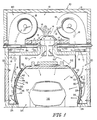
- a drying oven 10 for drying objects according to the present invention is illustrated in Fig. 1.
- the illustrated oven is constructed to raise the temperature of air contained in an air heating chamber 12 defined by an air heating chamber housing 13. Air is admitted into the air heating chamber 12 through both an air inlet 15 and a fresh air inlet 17 which admits fresh air that has not been previously circulated through the drying oven 10. Any air admitted into the air heating chamber 12 is heated by a gas-fired heater 14 placed in the air heating chamber 12 to a temperature of, for instance, about 580°F.
- This air temperature is reached by the addition of about 2,500,000 BTU/hr of thermal energy derived from the heat of combustion of natural gas burning in the illustrated air heating chamber 12.
- Alternative means of heating air are also contemplated for this invention, such as heating using oil or coal fired heaters, electrical heating methods, or using waste heat derived from other processes.
- the gas-fired heater 14 provides the most economical means of heating large volumes of air.
- Heated air represented by the large arrows 16 in Fig. 1, is drawn into a blower 18 which exhausts the heated air 16 from the air heating chamber 12 through an air outlet 19.
- the blower 18 may be a propellor, centrifugal or other type fan.
- the blower 18 used in an operational embodiment of this invention is capable of moving about 13,245 cubic feet per minute of heated air 16 through the air outlet 19.
- the heated air 16 blown out of the air heating chamber 12 by the blower 18 is channeled by a hot air conduit 20 toward a first wall 22.
- the first wall 22 is formed to have hot air passageway means 24 which illustratively include a plurality of apertures 26.
- the apertures 26 are typically spaced longitudinally along the lower portion of the first wall 22 and permit the transfer of hot air from the hot air conduit 20 through the first wall 22 upwardly into an air passageway 28.
- the air passageway 28 is defined in part by the first wall 22 and a second wall 30, and is in communication with the hot air conduit 20 via the apertures 26 that collectively form the hot air passageway means 24. It will be appreciated that the apertures 26, being in the lower portion of the wall 22, will heat the lower portion of the wall 30 to a temperature hotter than its upper portion.
- a schematic block diagram of an air circulation system 80 for the drying oven 10 is shown in Fig. 2.
- the hot air 16 produced within the air heating chamber 12 is used as a source of heat to enable the radiative emission of infrared heat by the second wall 30.
- the second wall 30 has an absorbing surface 70 and a radiating surface 74.
- Heat, provided by the convective contact between the absorbing surface 70 and hot air 16 moving within the air passageway 28, is transferred through the wall by conduction and emitted as infrared radiation 76 from the radiating surface 74.
- This infrared radiation having a spectrum approximately equivalent to a blackbody heated to between about 400 and 430 degrees Fahrenheit, acts to cure or dry coated objects such as a automobile 36 placed within the drying chamber 34.
- the amount of infrared radiation 76 incident at any point or a coated surface 37 of the automobile 36 may vary. However, since this variance in incident infrared radiation 76 causes differential heating of the coated surface 37, the coated surface 37 may form creases or wrinkles during the drying process. To evenly dry all points of the coated surface 37, the present device causes predetermined areas of the second wall 30 to emit a greater flux of infrared radiation 76, so that those areas of the coated surface 37 originally receiving lesser amounts of infrared radiation 76 will be heated to the same temperature as other points on the coated surface 37 of the automobile 36.
- Increasing the flux of infrared radiation 76 is achieved by local increases in the temperature of predetermined portions of the radiating surface 74 of the second wall 30.
- the temperature increases are enabled by increasing the amount of heat transferred from the hot air 16 to those predetermined portions of the absorbing surface 70 of the second wall 30.
- Increasing the amount of heat transferred is achieved by controlling the direction of the flow of hot air 16 into the air passageway 28.
- the flow of heated air 16 from the hot air conduit 20 into the air passageway 28 is precisely requlated by the placement of damper aperture 42 at a predetermined position in the first wall 22.
- damper aperture 42 As best shown in Fig. 4, heated air 16 passes through damper aperture 42 and strikes the absorbing surface 70 of the second wall 30.
- the hot air 16 is cooled to become cooled air 52 and the second wall 30 forms a high heat region 44 about the area of initial contact with the hot air 16.
- Regions of the second wall 30 that are not directly contacted by the flow of hot air 16 through the apertures 26 are heated nonetheless by conduction and contact with cooled air 52, but will generally have a lower temperature than the high heat region 44, and are therefore termed a low heat region 46.
- the extent to which the high heat region 44 is heated by convective contact with hot air 16 can be further controlled by regulating the amount of hot air 16 passing through the damper aperture 42 to contact the absorbing surface 70 of the second wall 30.
- sliding dampers 40 can be slidably attached to the first wall 22 selectively to close their associated damper apertures 42.
- the sliding dampers 40 can be fixed in completely closed positions to block the flow of hot air 16 as shown in 40a, to partially block the flow of hot air 16 as shown in 40b, or completely open so that the flow of hot air 16 through the damper aperture 42 is not impeded as shown in 40c.
- the high heat region 44 has a greater flux of infrared radiation 76 than the low heat region 46, as a result of the careful positioning of damper apertures 42, apertures 26 and sliding dampers 40, some drying problems with variable shape objects can be alleviated.
- the automobile 36 whose coated surface 37 would receive a varying amount of incident infrared radiation 76 if the radiating surface 74 had a constant temperature, can be more evenly dried if damper apertures 42 with sliding dampers 40 are provided to admit a controlled amount of hot air 16 to contact those portions of the second wall 30 that are furthest removed from coated surface 37 of the automobile 36.
- a plurality of apertures 26 and damper apertures 42 having a range of sizes are defined by the first wall 22.
- the damper apertures 42 can be unblocked to ensure an unimpeded flow of hot air 16 from the hot air conduit 20 into the air passageway 28, or the damper apertures 42 may be blocked by a plurality of sliding dampers 40 to prevent the flow of hot air 16 into the air passageway 28.
- Both the apertures 26 and the damper apertures 42, along with any sliding dampers 40 are in preferred embodiments serially arranged in parallel rows throughout the first wall 22. This arrangement provides great flexibility in regulating the amount of hot air 16 that is permitted to initially contact a predetermined portion of the absorbing surface 70 of the second wall 22 in order to ensure the production of a high heat region 44, or the continued maintenance of a low heat region 46.
- Access to the sliding dampers 4v is through an access door 60 forming a part of the hot air conduit 20.
- the access door 60 is removed, and an operator can reach inside the hot air conduit 20 to manually set the positions of the sliding dampers 40.
- Other means of setting the position of the sliding dampers 40 are also contemplated for this invention, and automatic or other type systems known to those skilled in the art of controlling valve devices can be used to regulate the blocking or unblocking of the apertures 16 by the sliding dampers 40.
Landscapes
- Engineering & Computer Science (AREA)
- Chemical & Material Sciences (AREA)
- Combustion & Propulsion (AREA)
- Life Sciences & Earth Sciences (AREA)
- Microbiology (AREA)
- Mechanical Engineering (AREA)
- General Engineering & Computer Science (AREA)
- Drying Of Solid Materials (AREA)
Applications Claiming Priority (2)
| Application Number | Priority Date | Filing Date | Title |
|---|---|---|---|
| US07/412,196 US4972606A (en) | 1989-09-25 | 1989-09-25 | Control damper for radiant oven |
| US412196 | 1989-09-25 |
Publications (2)
| Publication Number | Publication Date |
|---|---|
| EP0420554A1 true EP0420554A1 (de) | 1991-04-03 |
| EP0420554B1 EP0420554B1 (de) | 1993-10-13 |
Family
ID=23631988
Family Applications (1)
| Application Number | Title | Priority Date | Filing Date |
|---|---|---|---|
| EP90310436A Expired - Lifetime EP0420554B1 (de) | 1989-09-25 | 1990-09-24 | Kontrolldämpfer für Strahlungsofen |
Country Status (3)
| Country | Link |
|---|---|
| US (1) | US4972606A (de) |
| EP (1) | EP0420554B1 (de) |
| DE (1) | DE69003918D1 (de) |
Cited By (4)
| Publication number | Priority date | Publication date | Assignee | Title |
|---|---|---|---|---|
| WO1993005351A1 (en) * | 1991-08-29 | 1993-03-18 | Abb Flakt, Inc. | Method and apparatus for ventilating a paint baking oven |
| WO1995003517A1 (de) * | 1993-07-21 | 1995-02-02 | ABB Fläkt AB | Verfahren und heissluft-trockner zur trocknung beschichteter oberflächen |
| EP0706021A1 (de) * | 1994-10-08 | 1996-04-10 | Dürr GmbH | Trockner für eine Lackieranlage |
| CN102074319A (zh) * | 2010-12-31 | 2011-05-25 | 东莞市太阳线缆设备有限公司 | 烘炉自动风门 |
Families Citing this family (17)
| Publication number | Priority date | Publication date | Assignee | Title |
|---|---|---|---|---|
| US5102331A (en) * | 1991-08-02 | 1992-04-07 | Saturn Corporation | Radiant wall oven with temperature control |
| US5568692A (en) * | 1994-11-09 | 1996-10-29 | Durr Industries, Inc. | Paint drying oven with radiant energy floor |
| JP3133659B2 (ja) * | 1995-10-04 | 2001-02-13 | 株式会社大氣社 | 塗装乾燥炉 |
| FR2742525B1 (fr) * | 1995-12-19 | 1998-03-06 | Butagaz | Cabine de sechage |
| DE19709155C5 (de) * | 1997-03-06 | 2006-10-12 | Eisenmann Maschinenbau Gmbh & Co. Kg | Strahlungs-Zwischentrockner |
| EP1649229B1 (de) * | 2003-07-24 | 2011-04-27 | Eisenmann AG | Vorrichtung zur aushärtung einer aus einem material, das unter elektromagnetischer strahlung aushärtet, insbesondere aus einem uv-lack oder aus einem thermisch aushärtenden lack, bestehenden beschichtung eines gegenstandes |
| KR100666052B1 (ko) * | 2004-02-12 | 2007-01-09 | 조극래 | 원적외선이용한 건조장치 |
| US7264467B1 (en) * | 2005-06-22 | 2007-09-04 | International Thermal Systems, Llc | Convection oven with turbo flow air nozzle to increase air flow and method of using same |
| US20100050462A1 (en) * | 2008-08-29 | 2010-03-04 | Joseph Francis Attonito | Body exsiccation chamber |
| US20100273121A1 (en) * | 2009-04-27 | 2010-10-28 | Gleason James M | Oven exhaust fan system and method |
| US8438753B2 (en) | 2010-08-17 | 2013-05-14 | Josh Martin | System, method and apparatus for drying a shower |
| FR3012589A1 (fr) * | 2013-10-29 | 2015-05-01 | Sarl S P I C | Installation de chauffage d'une enceinte par rayonnement et convection, kit pour la realisation d'une telle enceinte |
| DE102014015705A1 (de) * | 2014-10-22 | 2016-04-28 | Wenker Gmbh & Co. Kg | Trockner für technische Gegenstände, insbesondere für lackierte Kraftfahrzeugkarosserien |
| US9958206B1 (en) | 2014-12-19 | 2018-05-01 | Arron Duvall | Curing oven |
| EP3252409B1 (de) * | 2015-01-26 | 2019-07-10 | Nissan Motor Co., Ltd. | Verfahren zum trocknen einer beschichtung |
| US10378819B2 (en) * | 2015-01-26 | 2019-08-13 | Nissan Motor Co., Ltd. | Paint baking oven and paint baking method |
| CN113508275A (zh) | 2019-02-20 | 2021-10-15 | 维斯兰热处理有限责任公司 | 模块化工业能量传递系统 |
Citations (4)
| Publication number | Priority date | Publication date | Assignee | Title |
|---|---|---|---|---|
| US4383823A (en) * | 1981-06-12 | 1983-05-17 | Williams Robert W | Radiant oven for baking bread |
| US4546553A (en) * | 1978-06-16 | 1985-10-15 | Best Willie H | Radiant wall oven and process of drying coated objects |
| EP0182972A1 (de) * | 1984-11-23 | 1986-06-04 | Heraeus Quarzschmelze Gmbh | Bestrahlungseinheit in Form eines Portals, insbesondere als Trocken- und Einbrennkanal für die Automobilindustrie |
| US4785552A (en) * | 1987-07-08 | 1988-11-22 | Best Willie H | Convection stabilized radiant oven |
Family Cites Families (7)
| Publication number | Priority date | Publication date | Assignee | Title |
|---|---|---|---|---|
| US3065551A (en) * | 1957-07-22 | 1962-11-27 | Samcoe Holding Corp | Reel dryer |
| GB2091858B (en) * | 1980-12-11 | 1984-09-26 | Infraroedteknik Ab | Surface treatment of objects |
| US4733481A (en) * | 1984-01-09 | 1988-03-29 | Gladd Industries, Inc. | Paint bake oven |
| DE3406789C1 (de) * | 1984-02-24 | 1989-07-20 | Adolf 7251 Weissach Berkmann | Verfahren zum Trocknen von insbesondere pulverbeschichteten Werkstuecken durch Infrarotstrahlung |
| US4600491A (en) * | 1984-05-17 | 1986-07-15 | Urquhart Thomas N | Workpiece drying apparatus |
| JPS62152564A (ja) * | 1985-12-27 | 1987-07-07 | Trinity Ind Corp | 塗装用乾燥炉 |
| US4771728A (en) * | 1986-09-08 | 1988-09-20 | Bgk Finishing Systems, Inc. | Automotive coating treatment apparatus |
-
1989
- 1989-09-25 US US07/412,196 patent/US4972606A/en not_active Expired - Fee Related
-
1990
- 1990-09-24 EP EP90310436A patent/EP0420554B1/de not_active Expired - Lifetime
- 1990-09-24 DE DE90310436T patent/DE69003918D1/de not_active Expired - Lifetime
Patent Citations (5)
| Publication number | Priority date | Publication date | Assignee | Title |
|---|---|---|---|---|
| US4546553A (en) * | 1978-06-16 | 1985-10-15 | Best Willie H | Radiant wall oven and process of drying coated objects |
| US4546553B1 (en) * | 1978-06-16 | 1993-04-13 | Radiant wall oven and process of drying coated objects | |
| US4383823A (en) * | 1981-06-12 | 1983-05-17 | Williams Robert W | Radiant oven for baking bread |
| EP0182972A1 (de) * | 1984-11-23 | 1986-06-04 | Heraeus Quarzschmelze Gmbh | Bestrahlungseinheit in Form eines Portals, insbesondere als Trocken- und Einbrennkanal für die Automobilindustrie |
| US4785552A (en) * | 1987-07-08 | 1988-11-22 | Best Willie H | Convection stabilized radiant oven |
Cited By (8)
| Publication number | Priority date | Publication date | Assignee | Title |
|---|---|---|---|---|
| WO1993005351A1 (en) * | 1991-08-29 | 1993-03-18 | Abb Flakt, Inc. | Method and apparatus for ventilating a paint baking oven |
| US5309650A (en) * | 1991-08-29 | 1994-05-10 | Abb Flakt, Inc. | Method and apparatus for ventilating a paint baking oven |
| WO1995003517A1 (de) * | 1993-07-21 | 1995-02-02 | ABB Fläkt AB | Verfahren und heissluft-trockner zur trocknung beschichteter oberflächen |
| US5657555A (en) * | 1993-07-21 | 1997-08-19 | Abb Flakt Ab | Process and hot-air dryer for dying coated surfaces |
| EP0706021A1 (de) * | 1994-10-08 | 1996-04-10 | Dürr GmbH | Trockner für eine Lackieranlage |
| US5661912A (en) * | 1994-10-08 | 1997-09-02 | Durr Gmbh | Drier for a painting plant |
| CN102074319A (zh) * | 2010-12-31 | 2011-05-25 | 东莞市太阳线缆设备有限公司 | 烘炉自动风门 |
| CN102074319B (zh) * | 2010-12-31 | 2013-02-27 | 东莞市太阳线缆设备有限公司 | 烘炉自动风门 |
Also Published As
| Publication number | Publication date |
|---|---|
| EP0420554B1 (de) | 1993-10-13 |
| US4972606A (en) | 1990-11-27 |
| DE69003918D1 (de) | 1993-11-18 |
Similar Documents
| Publication | Publication Date | Title |
|---|---|---|
| US4972606A (en) | Control damper for radiant oven | |
| US4011041A (en) | Tobacco curing and drying apparatus | |
| US2391195A (en) | Drier | |
| US5588830A (en) | Combined radiant and convection heating oven | |
| US3404618A (en) | Combination heating, ventilating and recirculating system for greenhouses | |
| US3997317A (en) | Glass annealing lehr having gas and electric heating means | |
| EP0118535B1 (de) | Kombinierte ofen- und rauchverbrennungsvorrichtung und deren betrieb | |
| CN211651096U (zh) | 一种烘干机及其热循环装置 | |
| CN110749181A (zh) | 一种烘干机及其热循环装置 | |
| WO1981000448A1 (en) | A method of supplying heat to a drying room and a drying room for carrying out the method | |
| JPH079355B2 (ja) | 輻射エネルギーを発生する装置と方法 | |
| JPH0573500U (ja) | 熱風循環炉 | |
| JPH053890U (ja) | 赤外線乾燥炉 | |
| JPH0343555B2 (de) | ||
| US2757920A (en) | Veneer dryer | |
| JPS6238217Y2 (de) | ||
| JPH0335989B2 (de) | ||
| JP2568913B2 (ja) | 穀物遠赤外熱風乾燥装置 | |
| GB2035768A (en) | Combination microwave and convection oven | |
| US3342413A (en) | Method of heating and apparatus therefor | |
| CA1277833C (en) | Reversible cross flow drying or curing oven | |
| JPS6249685B2 (de) | ||
| KR200143158Y1 (ko) | 농산물 건조기 연소실 구조 | |
| JPH0763483A (ja) | 熱流体再循環型加熱炉 | |
| GB1204870A (en) | A baking oven with means for air circulation |
Legal Events
| Date | Code | Title | Description |
|---|---|---|---|
| PUAI | Public reference made under article 153(3) epc to a published international application that has entered the european phase |
Free format text: ORIGINAL CODE: 0009012 |
|
| AK | Designated contracting states |
Kind code of ref document: A1 Designated state(s): BE DE ES FR GB IT SE |
|
| 17P | Request for examination filed |
Effective date: 19910422 |
|
| 17Q | First examination report despatched |
Effective date: 19920114 |
|
| GRAA | (expected) grant |
Free format text: ORIGINAL CODE: 0009210 |
|
| AK | Designated contracting states |
Kind code of ref document: B1 Designated state(s): BE DE ES FR GB IT SE |
|
| PG25 | Lapsed in a contracting state [announced via postgrant information from national office to epo] |
Ref country code: IT Free format text: LAPSE BECAUSE OF FAILURE TO SUBMIT A TRANSLATION OF THE DESCRIPTION OR TO PAY THE FEE WITHIN THE PRESCRIBED TIME-LIMIT;WARNING: LAPSES OF ITALIAN PATENTS WITH EFFECTIVE DATE BEFORE 2007 MAY HAVE OCCURRED AT ANY TIME BEFORE 2007. THE CORRECT EFFECTIVE DATE MAY BE DIFFERENT FROM THE ONE RECORDED. Effective date: 19931013 Ref country code: BE Effective date: 19931013 Ref country code: ES Free format text: THE PATENT HAS BEEN ANNULLED BY A DECISION OF A NATIONAL AUTHORITY Effective date: 19931013 Ref country code: SE Effective date: 19931013 Ref country code: DE Effective date: 19931013 Ref country code: FR Effective date: 19931013 |
|
| REF | Corresponds to: |
Ref document number: 69003918 Country of ref document: DE Date of ref document: 19931118 |
|
| EN | Fr: translation not filed | ||
| PLBE | No opposition filed within time limit |
Free format text: ORIGINAL CODE: 0009261 |
|
| STAA | Information on the status of an ep patent application or granted ep patent |
Free format text: STATUS: NO OPPOSITION FILED WITHIN TIME LIMIT |
|
| 26N | No opposition filed | ||
| PGFP | Annual fee paid to national office [announced via postgrant information from national office to epo] |
Ref country code: GB Payment date: 20010904 Year of fee payment: 12 |
|
| REG | Reference to a national code |
Ref country code: GB Ref legal event code: IF02 |
|
| PG25 | Lapsed in a contracting state [announced via postgrant information from national office to epo] |
Ref country code: GB Free format text: LAPSE BECAUSE OF NON-PAYMENT OF DUE FEES Effective date: 20020924 |
|
| GBPC | Gb: european patent ceased through non-payment of renewal fee |
Effective date: 20020924 |