EP0420499A2 - Tragbare Toilette - Google Patents
Tragbare Toilette Download PDFInfo
- Publication number
- EP0420499A2 EP0420499A2 EP90310290A EP90310290A EP0420499A2 EP 0420499 A2 EP0420499 A2 EP 0420499A2 EP 90310290 A EP90310290 A EP 90310290A EP 90310290 A EP90310290 A EP 90310290A EP 0420499 A2 EP0420499 A2 EP 0420499A2
- Authority
- EP
- European Patent Office
- Prior art keywords
- casing
- raw sewage
- heater
- bodies
- inner casing
- Prior art date
- Legal status (The legal status is an assumption and is not a legal conclusion. Google has not performed a legal analysis and makes no representation as to the accuracy of the status listed.)
- Granted
Links
Images





Classifications
-
- F—MECHANICAL ENGINEERING; LIGHTING; HEATING; WEAPONS; BLASTING
- F26—DRYING
- F26B—DRYING SOLID MATERIALS OR OBJECTS BY REMOVING LIQUID THEREFROM
- F26B25/00—Details of general application not covered by group F26B21/00 or F26B23/00
- F26B25/005—Treatment of dryer exhaust gases
-
- C—CHEMISTRY; METALLURGY
- C02—TREATMENT OF WATER, WASTE WATER, SEWAGE, OR SLUDGE
- C02F—TREATMENT OF WATER, WASTE WATER, SEWAGE, OR SLUDGE
- C02F11/00—Treatment of sludge; Devices therefor
- C02F11/12—Treatment of sludge; Devices therefor by de-watering, drying or thickening
- C02F11/13—Treatment of sludge; Devices therefor by de-watering, drying or thickening by heating
- C02F11/131—Treatment of sludge; Devices therefor by de-watering, drying or thickening by heating using electromagnetic or ultrasonic waves
-
- A—HUMAN NECESSITIES
- A47—FURNITURE; DOMESTIC ARTICLES OR APPLIANCES; COFFEE MILLS; SPICE MILLS; SUCTION CLEANERS IN GENERAL
- A47K—SANITARY EQUIPMENT; ACCESSORIES THEREFOR, e.g. TOILET ACCESSORIES
- A47K11/00—Closets without flushing; Urinals without flushing; Chamber pots; Chairs with toilet conveniences or specially adapted for use with toilets
- A47K11/02—Dry closets, e.g. incinerator closets
- A47K11/023—Incinerator closets
-
- F—MECHANICAL ENGINEERING; LIGHTING; HEATING; WEAPONS; BLASTING
- F23—COMBUSTION APPARATUS; COMBUSTION PROCESSES
- F23G—CREMATION FURNACES; CONSUMING WASTE PRODUCTS BY COMBUSTION
- F23G5/00—Incineration of waste; Incinerator constructions; Details, accessories or control therefor
- F23G5/02—Incineration of waste; Incinerator constructions; Details, accessories or control therefor with pretreatment
- F23G5/04—Incineration of waste; Incinerator constructions; Details, accessories or control therefor with pretreatment drying
-
- F—MECHANICAL ENGINEERING; LIGHTING; HEATING; WEAPONS; BLASTING
- F26—DRYING
- F26B—DRYING SOLID MATERIALS OR OBJECTS BY REMOVING LIQUID THEREFROM
- F26B25/00—Details of general application not covered by group F26B21/00 or F26B23/00
- F26B25/005—Treatment of dryer exhaust gases
- F26B25/007—Dust filtering; Exhaust dust filters
-
- F—MECHANICAL ENGINEERING; LIGHTING; HEATING; WEAPONS; BLASTING
- F26—DRYING
- F26B—DRYING SOLID MATERIALS OR OBJECTS BY REMOVING LIQUID THEREFROM
- F26B3/00—Drying solid materials or objects by processes involving the application of heat
- F26B3/18—Drying solid materials or objects by processes involving the application of heat by conduction, i.e. the heat is conveyed from the heat source, e.g. gas flame, to the materials or objects to be dried by direct contact
- F26B3/20—Drying solid materials or objects by processes involving the application of heat by conduction, i.e. the heat is conveyed from the heat source, e.g. gas flame, to the materials or objects to be dried by direct contact the heat source being a heated surface, e.g. a moving belt or conveyor
- F26B3/205—Drying solid materials or objects by processes involving the application of heat by conduction, i.e. the heat is conveyed from the heat source, e.g. gas flame, to the materials or objects to be dried by direct contact the heat source being a heated surface, e.g. a moving belt or conveyor the materials to be dried covering or being mixed with heated inert particles which may be recycled
-
- F—MECHANICAL ENGINEERING; LIGHTING; HEATING; WEAPONS; BLASTING
- F26—DRYING
- F26B—DRYING SOLID MATERIALS OR OBJECTS BY REMOVING LIQUID THEREFROM
- F26B3/00—Drying solid materials or objects by processes involving the application of heat
- F26B3/32—Drying solid materials or objects by processes involving the application of heat by development of heat within the materials or objects to be dried, e.g. by fermentation or other microbiological action
- F26B3/34—Drying solid materials or objects by processes involving the application of heat by development of heat within the materials or objects to be dried, e.g. by fermentation or other microbiological action by using electrical effects
- F26B3/343—Drying solid materials or objects by processes involving the application of heat by development of heat within the materials or objects to be dried, e.g. by fermentation or other microbiological action by using electrical effects in combination with convection
-
- F—MECHANICAL ENGINEERING; LIGHTING; HEATING; WEAPONS; BLASTING
- F26—DRYING
- F26B—DRYING SOLID MATERIALS OR OBJECTS BY REMOVING LIQUID THEREFROM
- F26B3/00—Drying solid materials or objects by processes involving the application of heat
- F26B3/32—Drying solid materials or objects by processes involving the application of heat by development of heat within the materials or objects to be dried, e.g. by fermentation or other microbiological action
- F26B3/34—Drying solid materials or objects by processes involving the application of heat by development of heat within the materials or objects to be dried, e.g. by fermentation or other microbiological action by using electrical effects
- F26B3/347—Electromagnetic heating, e.g. induction heating or heating using microwave energy
-
- F—MECHANICAL ENGINEERING; LIGHTING; HEATING; WEAPONS; BLASTING
- F26—DRYING
- F26B—DRYING SOLID MATERIALS OR OBJECTS BY REMOVING LIQUID THEREFROM
- F26B9/00—Machines or apparatus for drying solid materials or objects at rest or with only local agitation; Domestic airing cupboards
- F26B9/06—Machines or apparatus for drying solid materials or objects at rest or with only local agitation; Domestic airing cupboards in stationary drums or chambers
- F26B9/08—Machines or apparatus for drying solid materials or objects at rest or with only local agitation; Domestic airing cupboards in stationary drums or chambers including agitating devices, e.g. pneumatic recirculation arrangements
- F26B9/082—Machines or apparatus for drying solid materials or objects at rest or with only local agitation; Domestic airing cupboards in stationary drums or chambers including agitating devices, e.g. pneumatic recirculation arrangements mechanically agitating or recirculating the material being dried
-
- C—CHEMISTRY; METALLURGY
- C02—TREATMENT OF WATER, WASTE WATER, SEWAGE, OR SLUDGE
- C02F—TREATMENT OF WATER, WASTE WATER, SEWAGE, OR SLUDGE
- C02F2103/00—Nature of the water, waste water, sewage or sludge to be treated
- C02F2103/005—Black water originating from toilets
-
- F—MECHANICAL ENGINEERING; LIGHTING; HEATING; WEAPONS; BLASTING
- F23—COMBUSTION APPARATUS; COMBUSTION PROCESSES
- F23G—CREMATION FURNACES; CONSUMING WASTE PRODUCTS BY COMBUSTION
- F23G2202/00—Combustion
- F23G2202/70—Combustion with application of specific energy
- F23G2202/701—Electrical fields
-
- F—MECHANICAL ENGINEERING; LIGHTING; HEATING; WEAPONS; BLASTING
- F23—COMBUSTION APPARATUS; COMBUSTION PROCESSES
- F23G—CREMATION FURNACES; CONSUMING WASTE PRODUCTS BY COMBUSTION
- F23G2204/00—Supplementary heating arrangements
- F23G2204/20—Supplementary heating arrangements using electric energy
- F23G2204/203—Microwave
-
- F—MECHANICAL ENGINEERING; LIGHTING; HEATING; WEAPONS; BLASTING
- F23—COMBUSTION APPARATUS; COMBUSTION PROCESSES
- F23G—CREMATION FURNACES; CONSUMING WASTE PRODUCTS BY COMBUSTION
- F23G2204/00—Supplementary heating arrangements
- F23G2204/20—Supplementary heating arrangements using electric energy
- F23G2204/204—Induction
-
- Y—GENERAL TAGGING OF NEW TECHNOLOGICAL DEVELOPMENTS; GENERAL TAGGING OF CROSS-SECTIONAL TECHNOLOGIES SPANNING OVER SEVERAL SECTIONS OF THE IPC; TECHNICAL SUBJECTS COVERED BY FORMER USPC CROSS-REFERENCE ART COLLECTIONS [XRACs] AND DIGESTS
- Y02—TECHNOLOGIES OR APPLICATIONS FOR MITIGATION OR ADAPTATION AGAINST CLIMATE CHANGE
- Y02A—TECHNOLOGIES FOR ADAPTATION TO CLIMATE CHANGE
- Y02A50/00—TECHNOLOGIES FOR ADAPTATION TO CLIMATE CHANGE in human health protection, e.g. against extreme weather
- Y02A50/30—Against vector-borne diseases, e.g. mosquito-borne, fly-borne, tick-borne or waterborne diseases whose impact is exacerbated by climate change
Definitions
- the present invention relates to a raw sewage drying apparatus for disposing of raw sewage, which apparatus can be utilised outdoors, in a transportation means such as a vessel or train, or in a tunnel through which a tank truck used for collecting raw sewage (hereafter referred to simply as a vacuum truck) cannot go.
- a transportation means such as a vessel or train
- a tank truck used for collecting raw sewage hereafter referred to simply as a vacuum truck
- the raw sewage discharged from the human body is typically discharged to a sewage system by use of a flush toilet and the like in an ordinary house or is discharged into a river after being temporarily stored in a holding tank and purified therein.
- a flush toilet and the like in an ordinary house or is discharged into a river after being temporarily stored in a holding tank and purified therein.
- temporary toilet facilities must be provided to dispose of the raw sewage.
- Transportation vehicles such as buses, trains, vessels, etc., which operate over long distances are provided with an exclusive tank for storing and holding the discharged raw sewage.
- the raw sewage in this tank is subjected to a deodorising treatment by chemicals, and thereafter collected by a vacuum truck.
- the raw sewage is stored in the state as discharged from the human body, and thereafter collected so that disposal of the raw sewage is unhygienic. Also, a long period of use of the tank creates sewage residue on the tank which causes an odious smell.
- the present inventor proposed a drying apparatus having a casing provided with stirring blades and heating bodies therein in which the raw sewage is stirred by the rotation of the stirring blades and heated by heat generated by the heating bodies whereby the raw sewage is dried in a short period of time, as disclosed in Japanese Patent Laid-Open Publications Nos. 63-124150, 63-172852, 63-190857, 63-292789 and Application No. 63-198858 according to which claim 1 has been precharacterised.
- an outer periphery of the casing storing the raw sewage is heated by the heat generated by the burner or the heat converted from electricity by a heater.
- the metal casing storing the raw sewage is first heated which entails poor thermal efficiency.
- a raw sewage drying apparatus will be described with reference to Figures 1 to 4. Described in the first embodiment is a temporary toilet incorporating a raw sewage drying apparatus movable by a truck or the like.
- the temporary toilet 1 is made of reinforced synthetic resin plastic and has a box shape.
- the toilet 1 has a base 2 which can be supported on a surface of the earth and which has a roofed house 3 fixed thereto.
- a door 4 is attached to a front portion of the house 3.
- the temporary toilet 1 has inside thereof a drying apparatus 5 which is fixed to an upper portion of the base 2.
- a stool 6 is fixed to an upper portion of the drying apparatus 5 for receiving the raw sewage.
- the base 2 has a dust collection unit 7 at the side thereof which is provided with a diffusion pipe 8 at the upper portion thereof for expelling vapour from the raw sewage to the atmosphere.
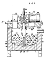
- the raw sewage drying apparatus 5 comprises an airtight first or inner casing 13, a rotatable drive shaft unit 23 provided in the first casing 13, a stirring means 28 fixed to the drive shaft unit 23 and having a plurality of blades for stirring raw sewage stored in the first casing 13, a plurality of elements 29 to be heated (hereinafter referred to as balls) contained in the first casing 13, said balls 29 being adapted to be heated by electromagnetic radiation, and a magnetron 32 provided outside the first casing 13 for emitting electromagnetic radiation toward the first casing 13.
- the raw sewage drying apparatus 5 also comprises an outer casing 11 made of thin steel plate of a cubic shape open at the upper portion thereof.
- An inner cover 15 is fixed to a top peripheral surface of the inner casing 13, a heat insulating material 17 made of glass, wool, etc., interposed between the outer cover 12 and the inner cover 15 and a heat insulating material 16 of glass, wool, etc., interposed in the space 10 between the outer casing 11 and the inner casing 13.
- the magnetron 32 is fixed to and above the inner cover 15 for generating microwave radiation (hereinafter referred to as microwaves), an antenna 33 protrudes from the magnetron 32 directed downward through a through hole 34 provided on the inner cover 15 for radiating the microwaves towards the dielectric elements or balls 29, described later.
- Bearings 21, 22 are fixed one each to central portions of the outer cover 12 and the inner cover 15.
- the drive shaft 23 is hollow and rotatably mounted by the bearings 21, 22 and penetrates vertically inside the outer casing 11 and the inner casing 13 substantially along the central vertical axis thereof.
- a lower metal shaft piece 24 fixed to the lower portion of the drive shaft 23 has a concave recess in a lower end thereof for receiving therein a projection 25 protruding upwardly from the bottom of the inner casing 13 for rotatably supporting the lower end of the drive pipe 23.
- a vent passage 26 extends axially through the lower metal shaft piece 24 and branches at the lower portion thereof to define communication holes 27 to communicate with the inside of the inner casing 13.
- Four radially-projecting stirring blades 28 are fixed to the lower metal piece 24 at 90° angular intervals, as shown in Figure 3, and positioned close to the curved bottom of the inner casing 13.
- An upper metal shaft piece 35 is coaxially fixed to the upper portion of the drive pipe 23 and projects upwardly above the outer cover 12.
- a vent passage 36 vertically penetrates the upper metal shaft piece 35, a worm gear 39 fixed to the upper metal shaft piece 35.
- a worm 41 engages with the worm gear 39.
- a sprocket wheel 40 fixed to the worm 41.
- a sprocket wheel 43 fixed to a motor 44 mounted on the outer cover 12.
- a chain 42 entrained around the sprocket wheels 40 and 43 for transmitting the output of the motor to the worm 41.
- the plurality of dielectric elements such as balls 29 may be made of ceramic, such as alumina or metal.
- An introduction pipe 30 vertically penetrating the covers 12 and 15 for communicating between the stool 6 and the inner casing 13 so that the raw sewage is introduced from the stool 6 to the inner casing 13, and a shutter or valve 31 provided within the introduction pipe 30 prevents odours and hot air from flowing back toward the stool 6.
- the raw sewage drying apparatus is connected to peripheral devices, as illustrated in Figure 4.
- a sleeve 37 fixed to the upper metal piece 35 is connected to a blower pipe 46 which is connected to a blower 47 for introducing fresh air.
- the blower 47 comprises a motor 48 and a fan 49 driven by the motor 48.
- a discharge duct 60 is provided at the upper side surface of the inner casing 13 to communicate the interior of the inner casing 11 with the atmosphere via the diffusion pipe 8.
- the duct 60 is connected to a dust collector 50, which collector 50 has therein a reheating electric heater 51 at the upper portion thereof and a filter 52 at the middle portion thereof and a catalyst 53 made of platinum etc. fixed to the lower portion thereof.
- the output of the dust collector 50 is connected to a blower 54 which comprises a motor 55 and a fan 56 driven by the motor 55 and connects to the diffusion pipe 8 so that the air and the vapor passes through the blower 54 into the diffusion pipe 8.
- the user enters the temporary toilet 1 and discharges the raw sewage into the stool 6.
- the discharged raw sewage drops via the introduction pipe 30 into the inner casing 13 and is stored therein temporarily.
- the inner casing 13 stores the predetermined amount of the raw sewage, which entails a drying operation of the raw sewage.
- the shutter 31 closes the introduction pipe 30 to thereby start the drying operation.
- the inner casing 13 is prevented from communicating with the outside. Accordingly, the bad smell emitted by the raw sewage in the inner casing 13 is prevented from diffusing outside through the stool 6. Furthermore, heat within the inner casing 13 is prevented from being transmitted to the outside through the introduction pipe 30 whereby the thermal efficiency can be improved.
- the motors 44, 48, 55 are operated respectively.
- the fan 49 is driven by the motor 48 so that the fresh air flows through the blower pipe 46 and is introduced into the drive pipe 23 through the communication holes 38, 36.
- the fresh air then flows through vent passage 26 to the communication holes 27 and is discharged at the bottom of the inner casing 13.
- the air in the inner casing 13 flows toward the diffusion pipe 8 via the duct 60 and the dust collector 50 having therein the catalyst 53.
- the air in the inner casing 13 is drawn into the dust collector 50 via the duct 60 and contacts the reheating heater 51 so that the temperature of the saturated vapor is increased and the minute dust etc. is removed by the filter 52 and contacts the catalyst 53. Since the saturated vapor is oxidized by the catalyst 53, the saturated vapor components causing the bad smell such as ammonia, bromine, etc. are oxidized so as to make the air odorless.
- the magnetron 32 is operated so that the microwave or electromagnetic wave is radiated from the antenna 33 of the magnetron 32 toward the inner casing 13.
- the microwave radiated from the antenna 33 is not radiated outside the casings 11 and 13, but is reflected within the inside space of the inner casing 13. Since both the casings 11, 13 are made of metal, the microwave reflected in the inner casing 13 directly heats the raw sewage stored in the inner casing 13 and the dielectric balls 29.
- the dielectric balls 29 are made of a material like alumina so as to be induced by the electromagnetic wave for generating heat, the dielectric balls 29 generate heat which is directly transmitted to the raw sewage which directly contacts the balls 29.
- liquid which is the primary component of the raw sewage starts to evaporate.
- the evaporated liquid flows through the discharge duct 60 into the collector 50 and diffuses outside through the diffusion pipe 8 via the blower 54.
- the microwaves generated by the magnetron 30 heat the raw sewage in the inner casing 13 and the dielectric balls 29, the heated raw sewage is oxidized by oxygen of the air in the inner casing 13 for thereby expediting the speed of oxidation since the air from the outside, namely the fresh air, is always discharged from the communicating holes 27 provided at the lower portion of the drive pipe 23.
- the liquid component of the collected raw sewage is evaporated and ashes of fiber or paper trash are residual in the inner casing 13.
- the non-evaporated ashes are rotated by the stirring blades 28 in the inner peripheral surface of the inner casing 13 together with the dielectric balls 29 so that the material other than the liquid component, namely the solid material, is crushed into a minute powder such as ashes.
- the ashes are blown up by the air discharged by the communication holes 27 and jetted in the discharge duct 60.
- the ashes which pass through the discharge duct 60 are caught by the filter 52 in the dust collector 50.
- the ashes are absorbed by and collected by the filter 52 so that the non-evaporated ashes and the trash residual in the inner casing 13 are cleaned by the air discharged through the communication holes 27 after the liquid component is evaporated.
- the drying operation can be effected to a state where no residual matter remains in the inner casing 13.
- a series of drying operations is completed upon completion of the evaporation of the liquid component of the raw sewage due to heating of the magnetron 32 and completion of crushing and cleaning of the minute solid material residual due to the operations of the stirring blades 28 and the dielectric heatin9 bodies 29.
- the inner casing 13 is automaticaliy cleaned and ready for the next disposal of raw sewage.
- the raw sewage drying apparatus according to the first embodiment has the following advantages.
- the microwave generated by the magnetron can heat the raw sewage as well as the dielectric elements directly contacting the raw sewage, the raw sewage can be directly heated by the microwave so that the thermal efficiency is remarkably increased and the energy loss is reduced compared with conventional heating of the casing.
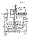
- the drying apparatus 5 comprises the constituents substantially the same as those of the first embodiment excepting that instead of the magnetron 32 there is provided an induction heater 18. That is, the drying apparatus comprises the airtight first casing 13, the rotatable drive shaft unit 23 provided in the first casing 13, the stirring means 28 fixed to the drive shaft unit 23 and having a plurality of blades for stirring raw sewage stored in the first casing 13, a plurality of elements or balls 29 contained in the first casing 13, said elements 29 being heated by an induction flux generated in the alternating electromagnetic field, and a heating means 32 provided outside the first casing 13 for generating an induction flux toward the first casing 13.
- the same components as those of the first embodiment are designated by the same numerals and explanations thereof are omitted.
- the induction heater 18 is fixed to the inner bottom of the outer casing 11 in the space defined between the inner bottom of the outer casing 11 and the lower surface of the inner casing 13.
- the induction heater 18 is composed of a core 19 having circular shape and coaxial with the outer casing 11 and a coil 29 accommodated in a groove defined as the coaxial shape.
- the plurality of elements 29 to be heated are made of conductive materials having relatively high resistance such as stainless steel, graphite, etc. contained in the inner casing 13.
- a high frequency generator 62 is connected to a commercial power source 61.
- the high frequency generator 62 generates the high frequency ranging from 1 K Hz to 1 M Hz on the basis of the commercial power source 61 and the output of the high frequency generator 62 is connected to the coil 20.
- the operation of the raw sewage drying apparatus according to the second embodiment is substantially the same as that of the first embodiment excepting the operation of the induction heater associated with the high frequency generator 61.
- the high frequency generator 62 increases the cycle of the frequency of the commercial power source to a high frequency of several K Hz to thereby generate the high frequency current.
- the high frequency current is supplied to the coil 20 which provides the alternating electric field.
- the alternating electromagnetic field formed by the high frequency passes the inner casing 13 which has a thin thickness but does not generate an overcurrent loss, and alternates in the inner casing 13. Since the elements 29 are made of materials of a relatively high resistance such as iron or stainless steel, an induction motive force is generated by passing the magnetic flux and overcurrent is generated so that the elements 29 per se generate the heat. Accordingly, the inner casing 13 is not heated or heated only a small amount, but the elements 29 are heated intensely so that the raw sewage contacting the elements 29 is heated by the heat of the elements 29.
- the raw sewage drying apparatus of the second embodiment when the elements 29 are of low resistance so that the alternating magnetic field passes the elements 29, no joule heat is generated in the elements 29, and hence only the inner casing is heated. Accordingly, the raw sewage in the inner casing 13 is heated by the heat generated at the bottom of the inner casing '3 whereby the liquid component thereof is evaporated. At this time, the elements 29 are rotated by the stirring blades 28 and crush the raw sewage to thereby expedite the transmittance of the heat to the raw sewage.
Landscapes
- Engineering & Computer Science (AREA)
- Mechanical Engineering (AREA)
- General Engineering & Computer Science (AREA)
- Life Sciences & Earth Sciences (AREA)
- Microbiology (AREA)
- Health & Medical Sciences (AREA)
- Molecular Biology (AREA)
- Biomedical Technology (AREA)
- Biotechnology (AREA)
- Public Health (AREA)
- Physics & Mathematics (AREA)
- Electromagnetism (AREA)
- Hydrology & Water Resources (AREA)
- Environmental & Geological Engineering (AREA)
- Water Supply & Treatment (AREA)
- Chemical & Material Sciences (AREA)
- Organic Chemistry (AREA)
- Non-Flushing Toilets (AREA)
- Drying Of Solid Materials (AREA)
- Treatment Of Sludge (AREA)
- Heat Treatment Of Water, Waste Water Or Sewage (AREA)
Applications Claiming Priority (4)
| Application Number | Priority Date | Filing Date | Title |
|---|---|---|---|
| JP1253469A JPH0796111B2 (ja) | 1989-09-28 | 1989-09-28 | 屎尿乾燥装置 |
| JP253469/89 | 1989-09-28 | ||
| JP312536/89 | 1989-12-01 | ||
| JP1312536A JPH0773698B2 (ja) | 1989-12-01 | 1989-12-01 | 屎尿乾燥装置 |
Publications (3)
| Publication Number | Publication Date |
|---|---|
| EP0420499A2 true EP0420499A2 (de) | 1991-04-03 |
| EP0420499A3 EP0420499A3 (en) | 1991-07-03 |
| EP0420499B1 EP0420499B1 (de) | 1995-04-26 |
Family
ID=26541216
Family Applications (1)
| Application Number | Title | Priority Date | Filing Date |
|---|---|---|---|
| EP90310290A Expired - Lifetime EP0420499B1 (de) | 1989-09-28 | 1990-09-20 | Tragbare Toilette |
Country Status (6)
| Country | Link |
|---|---|
| US (1) | US5152074A (de) |
| EP (1) | EP0420499B1 (de) |
| KR (1) | KR930001606B1 (de) |
| AU (1) | AU627056B2 (de) |
| CA (1) | CA2023497A1 (de) |
| DE (1) | DE69018911T2 (de) |
Cited By (6)
| Publication number | Priority date | Publication date | Assignee | Title |
|---|---|---|---|---|
| WO1993001149A1 (en) * | 1991-07-02 | 1993-01-21 | Hultstroem Bror Ivar | A composting method, composting apparatus and method and apparatus for delivering microwave energy to layered material |
| WO1996034239A1 (de) * | 1995-04-26 | 1996-10-31 | Schering Aktiengesellschaft | Vorrichtung zum trocknen von kristallinen substanzen |
| EP0824088A4 (de) * | 1996-02-29 | 2000-05-03 | Osaka Fuji Kogyo Kk | Abwasserfreie methode zur trocknung menschlicher fäkalien mit pulsierender verbrennung |
| WO2005038371A1 (de) * | 2003-10-08 | 2005-04-28 | Aguaprotec Gmbh & Co. Kg | Verfahren und vorrichtung zum trocknen eines insbesondere flüssigen oder pastösen trockengutes |
| WO2012150530A3 (en) * | 2011-04-30 | 2013-10-10 | The New Reclamation Group (Pty) Ltd. | An electrical induction heating assembly |
| CN112146408A (zh) * | 2020-09-27 | 2020-12-29 | 孙旭东 | 一种腻子粉原料用烘干装置 |
Families Citing this family (21)
| Publication number | Priority date | Publication date | Assignee | Title |
|---|---|---|---|---|
| IL99226A (en) * | 1990-08-24 | 1994-11-28 | Hachima Hiroki | Method and device for removing body secretions |
| AU653565B2 (en) * | 1990-12-21 | 1994-10-06 | Nikken Corporation | Raw sewage disposal apparatus and prefab for accomodating the same |
| AU2984892A (en) * | 1992-12-02 | 1994-06-16 | Japanic Corporation | Raw sewage disposal apparatus |
| JPH06218358A (ja) * | 1993-01-28 | 1994-08-09 | Japanic:Kk | 屎尿乾燥装置 |
| DE69401679T2 (de) * | 1993-04-26 | 1997-05-28 | Nikken Corp | Entsorgungsvorrichtung für Klärschlämme |
| US5447630A (en) * | 1993-04-28 | 1995-09-05 | Rummler; John M. | Materials treatment process and apparatus |
| DE9310741U1 (de) * | 1993-05-25 | 1993-09-02 | Umwelt Technics-Nord GmbH, 22851 Norderstedt | Vorrichtung zur Abscheidung flüchtiger Komponenten aus einem Grundstoff |
| JP2784378B2 (ja) * | 1993-11-19 | 1998-08-06 | 株式会社レンタルのニッケン | 屎尿処理装置 |
| JPH0857468A (ja) * | 1994-08-22 | 1996-03-05 | Japanic:Kk | 屎尿処理装置 |
| US5853579A (en) * | 1996-11-26 | 1998-12-29 | Wastech International Inc. | Treatment system |
| AUPO669597A0 (en) * | 1997-05-08 | 1997-06-05 | Rutledge, Peter John | Inductive heating method |
| US6618957B2 (en) * | 2000-08-16 | 2003-09-16 | John F. Novak | Method and apparatus for microwave utilization |
| GB0311959D0 (en) * | 2003-05-23 | 2003-06-25 | Glaxo Group Ltd | Energy delivery system |
| US7211187B2 (en) * | 2004-10-29 | 2007-05-01 | Steven Lumbert | Mobile or stationary modular self-contained dehydration toilet, dehydration engine, and gray water recovery system |
| EP2476483A1 (de) * | 2006-12-14 | 2012-07-18 | Micro Recovery Solutions LLC | Recycling- und Materialwiedergewinnungssystem sowie zugehöriges Verfahren |
| US9951281B2 (en) | 2006-12-14 | 2018-04-24 | John Otis Farneman | Microwave based systems and methods for obtaining carbonaceous compounds from polypropylene-containing products |
| US7518092B2 (en) * | 2007-03-15 | 2009-04-14 | Capital Technologies, Inc. | Processing apparatus with an electromagnetic launch |
| US9867511B1 (en) | 2009-07-16 | 2018-01-16 | Jerry Duane Wilburg | High efficiency evaporative/dehydration toilets |
| US9301659B1 (en) * | 2009-07-16 | 2016-04-05 | Jerry Duane Wilburg | High efficiency evaporative/dehydration toilets |
| CN111156792A (zh) * | 2020-01-20 | 2020-05-15 | 广州福滔微波设备有限公司 | 一种隧道式微波烘干设备 |
| GB2610191B (en) * | 2021-08-24 | 2024-02-28 | Univ Cranfield | Soild waste processing apparatus |
Family Cites Families (2)
| Publication number | Priority date | Publication date | Assignee | Title |
|---|---|---|---|---|
| DK148386A (da) * | 1986-04-02 | 1987-10-03 | Niels Peter Agdal | Fremgangsmaade til kontinuerlig, skaansom vakuumtoerring af en vaeske samttoerreapparat til udoevelse af fremgangsmaaden |
| EP0343817B1 (de) * | 1988-05-21 | 1993-12-08 | Japanic Corporation | Trocknungsvorrichtung für Faulschlamm |
-
1990
- 1990-08-17 CA CA002023497A patent/CA2023497A1/en not_active Abandoned
- 1990-08-17 AU AU61083/90A patent/AU627056B2/en not_active Ceased
- 1990-08-29 US US07/575,910 patent/US5152074A/en not_active Expired - Fee Related
- 1990-09-18 KR KR1019900014783A patent/KR930001606B1/ko not_active Expired - Fee Related
- 1990-09-20 DE DE69018911T patent/DE69018911T2/de not_active Expired - Fee Related
- 1990-09-20 EP EP90310290A patent/EP0420499B1/de not_active Expired - Lifetime
Cited By (6)
| Publication number | Priority date | Publication date | Assignee | Title |
|---|---|---|---|---|
| WO1993001149A1 (en) * | 1991-07-02 | 1993-01-21 | Hultstroem Bror Ivar | A composting method, composting apparatus and method and apparatus for delivering microwave energy to layered material |
| WO1996034239A1 (de) * | 1995-04-26 | 1996-10-31 | Schering Aktiengesellschaft | Vorrichtung zum trocknen von kristallinen substanzen |
| EP0824088A4 (de) * | 1996-02-29 | 2000-05-03 | Osaka Fuji Kogyo Kk | Abwasserfreie methode zur trocknung menschlicher fäkalien mit pulsierender verbrennung |
| WO2005038371A1 (de) * | 2003-10-08 | 2005-04-28 | Aguaprotec Gmbh & Co. Kg | Verfahren und vorrichtung zum trocknen eines insbesondere flüssigen oder pastösen trockengutes |
| WO2012150530A3 (en) * | 2011-04-30 | 2013-10-10 | The New Reclamation Group (Pty) Ltd. | An electrical induction heating assembly |
| CN112146408A (zh) * | 2020-09-27 | 2020-12-29 | 孙旭东 | 一种腻子粉原料用烘干装置 |
Also Published As
| Publication number | Publication date |
|---|---|
| AU627056B2 (en) | 1992-08-13 |
| AU6108390A (en) | 1991-04-11 |
| EP0420499B1 (de) | 1995-04-26 |
| EP0420499A3 (en) | 1991-07-03 |
| US5152074A (en) | 1992-10-06 |
| CA2023497A1 (en) | 1991-03-29 |
| DE69018911T2 (de) | 1995-08-24 |
| KR930001606B1 (ko) | 1993-03-06 |
| KR910011657A (ko) | 1991-08-07 |
| DE69018911D1 (de) | 1995-06-01 |
Similar Documents
| Publication | Publication Date | Title |
|---|---|---|
| EP0420499A2 (de) | Tragbare Toilette | |
| EP0343817B1 (de) | Trocknungsvorrichtung für Faulschlamm | |
| US5276924A (en) | Method and apparatus for disposing of body wastes | |
| EP0600132B1 (de) | Entsorgungsvorrichtung für Klärschlämme | |
| JP2008539062A (ja) | マイクロ波を用いた食品廃棄物処理装置 | |
| US11590544B2 (en) | Waste disposer | |
| EP0654565A2 (de) | Entsorgungsvorrichtung für Klärschlämme | |
| KR100510634B1 (ko) | 마이크로파음식물쓰레기처리기 | |
| US2700775A (en) | Combustion sanitation system | |
| JPH03114582A (ja) | 屎尿乾燥装置 | |
| JPH05301088A (ja) | 屎尿処理方法及びその装置 | |
| JPH0773698B2 (ja) | 屎尿乾燥装置 | |
| JP2002079228A (ja) | ゴミ処理システム及びゴミ炭化処理方法 | |
| JPH0531476A (ja) | ごみ処理装置 | |
| JPH0775702B2 (ja) | 屎尿乾燥装置 | |
| JP2610203B2 (ja) | 有機廃棄物処理装置 | |
| JP3083394B2 (ja) | 生ごみ処理装置 | |
| JP3058839B2 (ja) | 生ゴミ処理機 | |
| JPH0632805B2 (ja) | 屎尿乾燥装置 | |
| JPH05312472A (ja) | 乾燥処理装置 | |
| JP2506769B2 (ja) | 厨芥処理装置 | |
| JPH10259908A (ja) | 生ゴミの処理方法及び生ゴミ処理機 | |
| KR200155148Y1 (ko) | 간이 음식물쓰레기 처리장치 | |
| JPS63140212A (ja) | 厨芥処理装置 | |
| JPH0545844B2 (de) |
Legal Events
| Date | Code | Title | Description |
|---|---|---|---|
| PUAI | Public reference made under article 153(3) epc to a published international application that has entered the european phase |
Free format text: ORIGINAL CODE: 0009012 |
|
| AK | Designated contracting states |
Kind code of ref document: A2 Designated state(s): DE FR GB |
|
| PUAL | Search report despatched |
Free format text: ORIGINAL CODE: 0009013 |
|
| AK | Designated contracting states |
Kind code of ref document: A3 Designated state(s): DE FR GB |
|
| RAP1 | Party data changed (applicant data changed or rights of an application transferred) |
Owner name: JAPANIC CORPORATION |
|
| 17P | Request for examination filed |
Effective date: 19911223 |
|
| 17Q | First examination report despatched |
Effective date: 19930212 |
|
| GRAA | (expected) grant |
Free format text: ORIGINAL CODE: 0009210 |
|
| AK | Designated contracting states |
Kind code of ref document: B1 Designated state(s): DE FR GB |
|
| ET | Fr: translation filed | ||
| REF | Corresponds to: |
Ref document number: 69018911 Country of ref document: DE Date of ref document: 19950601 |
|
| PLBE | No opposition filed within time limit |
Free format text: ORIGINAL CODE: 0009261 |
|
| STAA | Information on the status of an ep patent application or granted ep patent |
Free format text: STATUS: NO OPPOSITION FILED WITHIN TIME LIMIT |
|
| 26N | No opposition filed | ||
| REG | Reference to a national code |
Ref country code: GB Ref legal event code: 732E |
|
| REG | Reference to a national code |
Ref country code: FR Ref legal event code: TP |
|
| PGFP | Annual fee paid to national office [announced via postgrant information from national office to epo] |
Ref country code: DE Payment date: 19970808 Year of fee payment: 8 |
|
| PGFP | Annual fee paid to national office [announced via postgrant information from national office to epo] |
Ref country code: FR Payment date: 19970827 Year of fee payment: 8 |
|
| PGFP | Annual fee paid to national office [announced via postgrant information from national office to epo] |
Ref country code: GB Payment date: 19970916 Year of fee payment: 8 |
|
| PG25 | Lapsed in a contracting state [announced via postgrant information from national office to epo] |
Ref country code: GB Free format text: LAPSE BECAUSE OF NON-PAYMENT OF DUE FEES Effective date: 19980920 |
|
| GBPC | Gb: european patent ceased through non-payment of renewal fee |
Effective date: 19980920 |
|
| PG25 | Lapsed in a contracting state [announced via postgrant information from national office to epo] |
Ref country code: FR Free format text: LAPSE BECAUSE OF NON-PAYMENT OF DUE FEES Effective date: 19990531 |
|
| PG25 | Lapsed in a contracting state [announced via postgrant information from national office to epo] |
Ref country code: DE Free format text: LAPSE BECAUSE OF NON-PAYMENT OF DUE FEES Effective date: 19990701 |
|
| REG | Reference to a national code |
Ref country code: FR Ref legal event code: ST |