EP0420105A2 - Differential pressure measuring device with autocontrol - Google Patents
Differential pressure measuring device with autocontrol Download PDFInfo
- Publication number
- EP0420105A2 EP0420105A2 EP90118312A EP90118312A EP0420105A2 EP 0420105 A2 EP0420105 A2 EP 0420105A2 EP 90118312 A EP90118312 A EP 90118312A EP 90118312 A EP90118312 A EP 90118312A EP 0420105 A2 EP0420105 A2 EP 0420105A2
- Authority
- EP
- European Patent Office
- Prior art keywords
- temperature
- differential pressure
- measuring
- measuring device
- sensor
- Prior art date
- Legal status (The legal status is an assumption and is not a legal conclusion. Google has not performed a legal analysis and makes no representation as to the accuracy of the status listed.)
- Granted
Links
Images
Classifications
-
- G—PHYSICS
- G01—MEASURING; TESTING
- G01L—MEASURING FORCE, STRESS, TORQUE, WORK, MECHANICAL POWER, MECHANICAL EFFICIENCY, OR FLUID PRESSURE
- G01L9/00—Measuring steady of quasi-steady pressure of fluid or fluent solid material by electric or magnetic pressure-sensitive elements; Transmitting or indicating the displacement of mechanical pressure-sensitive elements, used to measure the steady or quasi-steady pressure of a fluid or fluent solid material, by electric or magnetic means
- G01L9/0041—Transmitting or indicating the displacement of flexible diaphragms
- G01L9/0072—Transmitting or indicating the displacement of flexible diaphragms using variations in capacitance
-
- G—PHYSICS
- G01—MEASURING; TESTING
- G01L—MEASURING FORCE, STRESS, TORQUE, WORK, MECHANICAL POWER, MECHANICAL EFFICIENCY, OR FLUID PRESSURE
- G01L9/00—Measuring steady of quasi-steady pressure of fluid or fluent solid material by electric or magnetic pressure-sensitive elements; Transmitting or indicating the displacement of mechanical pressure-sensitive elements, used to measure the steady or quasi-steady pressure of a fluid or fluent solid material, by electric or magnetic means
- G01L9/12—Measuring steady of quasi-steady pressure of fluid or fluent solid material by electric or magnetic pressure-sensitive elements; Transmitting or indicating the displacement of mechanical pressure-sensitive elements, used to measure the steady or quasi-steady pressure of a fluid or fluent solid material, by electric or magnetic means by making use of variations in capacitance, i.e. electric circuits therefor
- G01L9/125—Measuring steady of quasi-steady pressure of fluid or fluent solid material by electric or magnetic pressure-sensitive elements; Transmitting or indicating the displacement of mechanical pressure-sensitive elements, used to measure the steady or quasi-steady pressure of a fluid or fluent solid material, by electric or magnetic means by making use of variations in capacitance, i.e. electric circuits therefor with temperature compensating means
Definitions
- the invention relates to a differential pressure measuring device with a liquid-filled single-chamber differential pressure sensor, which contains two measuring capacitors, the capacitances of which change in the opposite direction and with the temperature in the same direction with a differential pressure to be detected and are converted from associated capacitance measuring circuits to measuring signals which are used by a computing circuit for calculating the temperature and the temperature Differential pressure are supplied.
- a differential pressure measuring device of this type is known from DE-PS 35 04 329.
- the single-chamber differential pressure sensor consists of a cylindrical base body, on the two front sides of which a membrane is attached to form a cavity.
- the measuring capacitors are formed by layer electrodes which on the mutually facing surfaces of the Base body and the membranes are attached.
- the two cavities are connected to one another by a channel formed in the base body, and the entire volume of the common chamber formed in this way is filled with an incompressible liquid. If the pressures acting on the two membranes are of different magnitudes, the two membranes are deflected in the same direction as a result of the coupling by the liquid, so that one membrane approaches the base body and the other membrane removes it from the base body.
- the capacitances of the measuring capacitors change in opposite senses as a function of the differential pressure, the differential pressure being approximately proportional to the difference between the reciprocal capacitance values.
- the volume of the liquid changes as a result of a change in temperature
- the two membranes are deflected in opposite directions, so that they simultaneously approach or move away from the main body.
- the capacitances of the measuring capacitors change in the same direction as a function of the temperature, the temperature being approximately proportional to the sum of the reciprocal capacitance values.
- the arithmetic circuit calculates the temperature from the sum of the reciprocal capacitance values and uses the result to correct the temperature dependence of the differential pressure calculated from the difference between the reciprocal capacitance values.
- the object of the invention is to provide a differential pressure measuring device of the type specified, in which Faults and other causes of errors that lead to an incorrect measurement result are recognized and displayed with great certainty by self-monitoring.
- the differential pressure measuring device contains a temperature measuring device for the direct measurement of the temperature of the single-chamber differential pressure sensor and a comparison device which compares the temperature calculated from the capacitances of the measuring capacitors with the measured temperature and emits a signal indicating the existence of an error if the deviation between the compared temperatures exceeds a predetermined limit.
- every malfunction and cause of error which leads to an incorrect capacitance measurement also results in a deviation of the temperature calculated from the capacitance values from the temperature measured directly.
- the presence of a measurement error is thus reliably recognized and displayed even if the values of the calculated differential pressure and the calculated temperature are still plausible.
- malfunctions that lead to a complete failure of the measurement such as cable breaks, a defect in a capacitance measuring circuit or the like, are immediately recognized and displayed.
- the added temperature measuring device is also monitored for correct functioning, because any fault in the temperature measuring device also leads to a deviation of the measured temperature from the temperature calculated from the capacitance values. There is therefore a complete self-monitoring of the differential pressure measuring device with high intrinsic safety.
- the temperature measuring device preferably has a temperature sensor attached to the differential pressure sensor and a temperature measuring circuit connected to the temperature sensor.
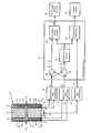
- the differential pressure measuring device shown in the drawing consists of a single-chamber differential pressure sensor 10 and an evaluation circuit.
- the single-chamber differential pressure sensor 10 has a cylindrical base body 11, on the two end faces of which two elastic membranes 12 and 13 are attached in a pressure-tight manner with the insertion of spacer rings 14 and 15 running around the circumference.
- the base body 11 and the membranes 12, 13 consist of an electrically insulating material, preferably of a metal oxide ceramic.
- the spacer rings 14 and 15 are preferably made of an electrically insulating material which effects the pressure-tight connection between the base body 11 and the membranes 12 and 13, for example of glass frit.
- the spacers 14, 15 keep the membranes 12, 13 at a distance from the base body 11, so that between each membrane 12, 13 and the end face of the base body 11 facing it there is a flat cavity 16 and 17, respectively.
- the two cavities 16 and 17 are connected to one another by an axial channel 18 formed in the base body 11, so that they form a common chamber which is sealed off from the outside in a pressure-tight manner.
- the entire volume of the chamber is filled with an incompressible, insulating liquid 20, for example with silicone oil.
- the inside of the membrane 12 facing the base body 11 is covered with a layer electrode 21, which lies opposite an annular layer electrode 22 on the end face of the base body 11 facing it.
- the inside of the membrane 13 is covered with a layer electrode 23, which lies opposite an annular layer electrode 24 on the end face of the base body 11 facing it.
- the layer electrodes 21, 22, 23, 24 are connected conductors 25, 26, 27, 28 connected to externally accessible connection points 31, 32, 33, 34.
- the connecting conductors 25 to 28 are layer conductor strips which are applied together with the associated layer electrodes 21 to 24 and run between the spacer rings 14, 15 and the base body 11 or the membranes 12, 13 to the outer circumference.
- the layer electrodes 21 to 24 can be applied together with the layer conductor strips 25 to 28 using thick-film technology.
- the layer electrode 21 forms with its opposing layer electrode 22 a first measuring capacitor 35 of the capacitance C 1, which is measurable between the connection points 31 and 32, and the layer electrode 23 forms with the opposing layer electrode 24 a second measuring capacitor 36 of the capacitance C 2, which between the Junctions 33 and 34 is measurable.
- the pressure P1 becomes greater than the pressure P2, it can deflect the membrane 12 towards the base body 11, with part of the incompressible liquid 20 being out the cavity 16 is displaced through the channel 18 into the cavity 17 so that the membrane 13 is deflected away from the base body 11 against the pressure P2.
- the distance between the layer electrodes 21 and 22 becomes smaller and the distance between the layer electrodes 23 and 24 increases. Accordingly, the capacity C1 is larger and the capacity C2 smaller.
- the evaluation circuit contains a first capacitance measuring circuit 41, which is connected to measure the capacitance C 1 to the connection points 31, 32, and a second capacitance measurement circuit 42, which is connected to measure the capacitance C 2 to the connection points 33, 34.
- Each capacitance measuring circuit is designed such that it outputs a measuring signal at the output which is proportional to the reciprocal value of the measured capacitance.
- the capacitance measurement circuit 41 outputs a measurement signal which is proportional to the value 1 / C1
- the capacitance measurement circuit 42 outputs a measurement signal which is proportional to the value 1 / C2.
- the measurement signals emitted by the two capacitance measuring circuits 41 and 42 are fed to a computing circuit 43 which calculates the differential pressure ⁇ P therefrom.
- the arithmetic circuit 43 contains a subtracting circuit 44 which receives the measurement signals from the two capacitance measurement circuits 41 and 42 and emits a signal at the output which is proportional to the difference 1 / C1 - 1 / C2 of the reciprocal capacitance values .
- This signal is fed to a differential pressure calculator 45.
- the computing circuit 43 contains a summing circuit 46, which also receives the measurement signals from the two capacitance measuring circuits 41 and 42 and emits a signal at the output which is proportional to the sum 1 / C1 + 1 / C2 of the reciprocal capacitance values.
- This signal is fed to a temperature calculator 47, which calculates the temperature T 1 of the single-chamber differential pressure sensor 10 therefrom.
- This temperature T 1 is also communicated to the differential pressure computer 45, which takes it into account in the calculation of the corrected differential pressure ⁇ P.
- the differential pressure computer 45 sees constant correction factors which have been determined during calibration of the single-chamber differential pressure sensor 10 and have been stored in the computing circuit 43. These correction factors relate, for example, to the zero point shift of the measured values due to manufacturing tolerances, the sensitivity of the single-chamber differential pressure sensor, etc.
- the differential pressure ⁇ P calculated by the differential pressure meter 45 can be displayed on a differential pressure display 48.
- the arithmetic circuit 43 can be designed in any manner known per se, for example with known analog or digital circuits.
- the arithmetic circuit is preferably formed by a suitably programmed microprocessor. If the measurement signals supplied by the capacitance measuring circuits 41 and 42 are not in a form which is directly suitable for processing by a microprocessor, the required analog-digital converter or interfaces must of course be inserted, as is known to the person skilled in the art.
- the part of the differential pressure measuring device described so far corresponds to the known prior art.
- the differential pressure measuring device shown differs from this prior art by the measures described below.
- a temperature sensor 50 is mounted so that it detects essentially the same temperature that is also calculated by the temperature calculator 47 from the capacitances C 1 and C 2 of the two measuring capacitors.
- the temperature sensor 50 is attached to the peripheral surface of the cylindrical base body 11.
- the temperature sensor 5 can be any temperature sensor known per se, for example a temperature-dependent resistor of the type PT 100.
- a temperature measuring circuit 51 is connected, which emits a measuring signal at the output, which corresponds to the temperature T2 detected by the temperature sensor 50.
- This output signal is fed to a comparison circuit 52, which on the other hand receives the output signal of the temperature calculator 47, which indicates the temperature T 1 calculated from the capacitance values C 1 and C 2.
- the comparison circuit 52 compares the calculated temperature T 1 with the measured temperature T 2. If there is a deviation between these two temperatures which exceeds a predetermined limit value, the comparison circuit 52 emits a signal which indicates that there is a cause of error in the differential pressure measuring device which leads to an incorrect measurement result.
- This signal can, for example, trigger an error alarm 53 or be used in another way to indicate the presence of an error and / or to prevent the use of the calculated differential pressure.
Landscapes
- Physics & Mathematics (AREA)
- General Physics & Mathematics (AREA)
- Measuring Fluid Pressure (AREA)
Abstract
Das Differenzdruckmeßgerät enthält einen flüssigkeitsgefüllten Einkanmer-Differenzdrucksensor (10), der zwei Meßkondensatoren enthält, deren Kapazitäten sich mit einem zu erfassenden Differenzdruck gegensinnig und mit der Temperatur gleichsinnig ändern und von zugeordneten Kapazitätsmeßschaltungen (41, 42) zu Meßsignalen umgeformt werden die einer Rechenschaltung (43) zur Berechnung der Temperatur und des Differenzdrucks zugeführt werden. Eine Temperaturmeßeinrichtung, die einen am Differenzdrucksensor angebrachten Temperatursensor (50) und eine mit dem Temperatursensor verbundene Temperaturmeßschaltung (51) aufweist, mißt unmittelbar die Temperatur des Einkammer-Differenzdrucksensors. Eine Vergleichseinrichtung (52) vergleicht die aus den Kapazitäten der Meßkondensatoren berechnete Temperatur mit der gemessenen Temperatur und gibt ein das Bestehen eines Fehlers anzeigendes Signal ab, wenn die Abweichung zwischen den verglichenen Temperaturen einen vorbestimmten Grenzwert überschreitet. Durch diese Selbstüberwachung werden Störungen und andere Fehlerursachen, die zu einem falschen Meßergebnis führen, mit großer Sicherheit erkannt und angezeigt.The differential pressure measuring device contains a liquid-filled single-channel differential pressure sensor (10), which contains two measuring capacitors, the capacitances of which change with a differential pressure to be detected in the opposite direction and with the temperature, and are converted into measuring signals by assigned capacitance measuring circuits (41, 42), which are then used in a computing circuit (43 ) for calculating the temperature and differential pressure. A temperature measuring device, which has a temperature sensor (50) attached to the differential pressure sensor and a temperature measuring circuit (51) connected to the temperature sensor, directly measures the temperature of the single-chamber differential pressure sensor. A comparison device (52) compares the temperature calculated from the capacitances of the measuring capacitors with the measured temperature and emits a signal indicating the existence of an error if the deviation between the compared temperatures exceeds a predetermined limit value. With this self-monitoring, faults and other causes of errors that lead to an incorrect measurement result are detected and displayed with great certainty.
Description
Die Erfindung betrifft ein Differenzdruckmeßgerät mit einem flüssigkeitsgefüllten Einkammer-Differenzdrucksensor, der zwei Meßkondensatoren enthält, deren Kapazitäten sich mit einem zu erfasssenden Differenzdruck gegensinnig und mit der Temperatur gleichsinnig ändern und von zugeordneten Kapazitätsmeßschaltungen zu Meßsignalen umgeformt werden, die einer Rechenschaltung zur Berechnung der Temperatur und des Differenzdrucks zugeführt werden.The invention relates to a differential pressure measuring device with a liquid-filled single-chamber differential pressure sensor, which contains two measuring capacitors, the capacitances of which change in the opposite direction and with the temperature in the same direction with a differential pressure to be detected and are converted from associated capacitance measuring circuits to measuring signals which are used by a computing circuit for calculating the temperature and the temperature Differential pressure are supplied.
Ein Differenzdruckmeßgerät dieser Art ist aus der DE-PS 35 04 329 bekannt. Der Einkammer-Differenzdrucksensor besteht aus einem zylindrischen Grundkörper, an dessen beiden Stirnseiten je eine Membran unter Bildung eines Hohlraums angebracht ist. Die Meßkondensatoren sind durch Schichtelektroden gebildet, die auf den einander zugewandten Flächen des Grundkörpers und der Membranen angebracht sind. Die beiden Hohlräume sind durch einen im Grundkörper gebildeten Kanal miteinander verbunden, und das ganze Volumen der auf diese Weise gebildeten gemeinsamen Kammer ist mit einer inkompressiblen Flüssigkeit gefüllt. Wenn die auf die beiden Membranen einwirkenden Drücke verschieden groß sind, werden die beiden Membranen infolge der Kopplung durch die Flüssigkeit in der gleichen Richtung ausgelenkt, so daß sich die eine Membran dem Grundkörper nähert und die andere Membran vom Grundkörper entfernt. Dadurch ändern sich die Kapazitäten der Meßkondensatoren in Abhängigkeit vom Differenzdruck gegensinnig, wobei der Differenzdruck näherungsweise der Differenz der reziproken Kapazitätswerte proportional ist. Wenn sich dagegen das Volumen der Flüssigkeit infolge einer Temperaturänderung ändert, werden die beiden Membranen in entgegengesetzten Richtungen ausgelenkt, so daß sie sich gleichzeitig dem Grundkörper nähern oder vom Grundkörper entfernen. Demzufolge ändern sich die Kapazitäten der Meßkondensatoren in der Abhängigkeit von der Temperatur gleichsinnig, wobei die Temperatur näherungsweise der Summe der reziproken Kapazitätswerte proportional ist. Die Rechenschaltung berechnet die Temperatur aus der Summe der reziproken Kapazitätswerte und verwendet das Ergebnis zur Korrktur der Temperaturabhängigkeit des aus der Differenz der reziproken Kapazitätswerte berechneten Differenzdrucks.A differential pressure measuring device of this type is known from DE-PS 35 04 329. The single-chamber differential pressure sensor consists of a cylindrical base body, on the two front sides of which a membrane is attached to form a cavity. The measuring capacitors are formed by layer electrodes which on the mutually facing surfaces of the Base body and the membranes are attached. The two cavities are connected to one another by a channel formed in the base body, and the entire volume of the common chamber formed in this way is filled with an incompressible liquid. If the pressures acting on the two membranes are of different magnitudes, the two membranes are deflected in the same direction as a result of the coupling by the liquid, so that one membrane approaches the base body and the other membrane removes it from the base body. As a result, the capacitances of the measuring capacitors change in opposite senses as a function of the differential pressure, the differential pressure being approximately proportional to the difference between the reciprocal capacitance values. If, on the other hand, the volume of the liquid changes as a result of a change in temperature, the two membranes are deflected in opposite directions, so that they simultaneously approach or move away from the main body. As a result, the capacitances of the measuring capacitors change in the same direction as a function of the temperature, the temperature being approximately proportional to the sum of the reciprocal capacitance values. The arithmetic circuit calculates the temperature from the sum of the reciprocal capacitance values and uses the result to correct the temperature dependence of the differential pressure calculated from the difference between the reciprocal capacitance values.
Mit diesem bekannten Differenzdruckmeßgerät wird zwar ein von Temperaturschwankungen unabhängiges Meßergebnis des Differenzdrucks erhalten, doch können Störungen und andere Fehlerursachen, die zu einem falschen Meßergebnis führen, nicht erkannt werden. Ursachen für nicht erkennbare Meßfehler sind beispielsweise ein Flüssigkeitsverlust infolge von Undichtigkeit, Änderungen der Membraneigenschaften infolge von Beschädigung oder Abnutzung usw.With this known differential pressure measuring device, a measurement result of the differential pressure independent of temperature fluctuations is obtained, but failures and other causes of errors which lead to an incorrect measurement result cannot be recognized. Causes of undetectable measurement errors are, for example, a loss of liquid due to leakage, changes in the membrane properties due to damage or wear, etc.
Aufgabe der Erfindung ist die Schaffung eines Differenzdruckmeßgeräts der eingangs angegebenen Art, bei welchem Störungen und andere Fehlerursachen, die zu einem falschen Meßergebnis führen, durch eine Selbstüberwachung mit großer Sicherheit erkannt und angezeigt werden.The object of the invention is to provide a differential pressure measuring device of the type specified, in which Faults and other causes of errors that lead to an incorrect measurement result are recognized and displayed with great certainty by self-monitoring.
Zur Lösung dieser Aufgabe enthält das Differenzdruckmeßgerät nach der Erfindung eine Temperaturmeßeinrichtung zur unmittelbaren Messung der Temperatur des Einkammer-Differenzdrucksensors und eine Vergleichseinrichtung, die die aus den Kapazitäten der Meßkondensatoren berechnete Temperatur mit der gemessenen Temperatur vergleicht und ein das Bestehen eines Fehlers anzeigendes Signal abgibt, wenn die Abweichung zwischen den verglichenen Temperaturen einen vorbestimmten Grenzwert überschreitet.To achieve this object, the differential pressure measuring device according to the invention contains a temperature measuring device for the direct measurement of the temperature of the single-chamber differential pressure sensor and a comparison device which compares the temperature calculated from the capacitances of the measuring capacitors with the measured temperature and emits a signal indicating the existence of an error if the deviation between the compared temperatures exceeds a predetermined limit.
Bei dem Differenzdruckmeßgerät nach der Erfindung ergibt jede Störung und Fehlerursache, die zu einer falschen Kapazitätsmessung führt, auch eine Abweichung der aus den Kapazitätswerten berechneten Temperatur von der unmittelbar gemessenen Temperatur. Somit wird das Vorliegen eines Meßfehlers mit Sicherheit selbst dann erkannt und angezeigt, wenn die Werte des berechneten Differenzdrucks und der berechneten Temperatur durchaus noch plausibel sind. Natürlich werden auch Störungen, die zu einem vollständigen Ausfall der Messung führen, wie Kabelbrüche, Defekt einer Kapazitätsmeßschaltung oder dergleichen, sofort erkannt und angezeigt. Darüber hinaus wird auch die hinzugefügte Temperaturmeßeinrichtung auf richtiges Funktionieren überwacht, denn jede Störung der Temperaturmeßeinrichtung führt ebenfalls zu einer Abweichung der gemessenen Temperatur von der aus den Kapazitätswerten berechneten Temperatur. Es besteht also eine vollständige Selbstüberwachung des Differenzdruckmeßgeräts mit hoher Eigensicherheit.In the differential pressure measuring device according to the invention, every malfunction and cause of error which leads to an incorrect capacitance measurement also results in a deviation of the temperature calculated from the capacitance values from the temperature measured directly. The presence of a measurement error is thus reliably recognized and displayed even if the values of the calculated differential pressure and the calculated temperature are still plausible. Of course, malfunctions that lead to a complete failure of the measurement, such as cable breaks, a defect in a capacitance measuring circuit or the like, are immediately recognized and displayed. In addition, the added temperature measuring device is also monitored for correct functioning, because any fault in the temperature measuring device also leads to a deviation of the measured temperature from the temperature calculated from the capacitance values. There is therefore a complete self-monitoring of the differential pressure measuring device with high intrinsic safety.
Vorzugsweise weist die Temperaturmeßeinrichtung einen am Differenzdrucksensor angebrachten Temperatursensor und eine mit dem Temperatursensor verbundene Temperaturmeßschaltung auf.The temperature measuring device preferably has a temperature sensor attached to the differential pressure sensor and a temperature measuring circuit connected to the temperature sensor.
Weitere Merkmale und Vorteile der Erfindung ergeben sich aus der folgenden Beschreibung eines Ausführungsbeispiels, das schematisch in der einzigen Figur der Zeichnung dargestellt ist.Further features and advantages of the invention result from the following description of an exemplary embodiment, which is shown schematically in the single figure of the drawing.
Das in der Zeichnung dargestellte Differenzdruckmeßgerät besteht aus einem Einkammer-Differenzdrucksensor 10 und einer Auswerteschaltung. Der Einkammer-Differenzdrucksensor 10 hat einen zylindrischen Grundkörper 11, an dessen beiden Stirnseiten zwei elastische Membranen 12 und 13 unter Einfügung von um den Umfang verlaufenden Distanzringen 14 bzw. 15 druckdicht befestigt sind. Der Grundkörper 11 und die Membranen 12, 13 bestehen aus einem elektrisch isolierenden Material, vorzugsweise aus einer Metalloxidkeramik. Desgleichen bestehen die Distanzringe 14 und 15 vorzugsweise aus einem elektrisch isolierenden Material, das die druckdichte Verbindung zwischen dem Grundkörper 11 und den Membranen 12 und 13 bewirkt, beispielsweise aus Glasfritte. Durch die Distanzringe 14, 15 sind die Membranen 12, 13 im Abstand vom Grundkörper 11 gehalten, so daß zwischen jeder Membran 12, 13 und der ihr zugewandten Stirnfläche des Grundkörpers 11 ein flacher Hohlraum 16 bzw. 17 besteht. Die beiden Hohlräume 16 und 17 sind durch einen im Grundkörper 11 gebildeten axialen Kanal 18 miteinander verbunden, so daß sie eine gemeinsame Kammer bilden, die druckdicht nach außen abgeschlossen ist. Das gesamte Volumen der Kammer ist mit einer inkompressiblen, isolierenden Flüssigkeit 20 gefüllt, beispielsweise mit Silikonöl.The differential pressure measuring device shown in the drawing consists of a single-chamber
Die dem Grundkörper 11 zugewandte Innenseite der Membran 12 ist mit einer Schichtelektrode 21 belegt, die einer ringförmigen Schichtelektrode 22 auf der ihr zugewandten Stirnfläche des Grundkörpers 11 gegenüberliegt. Desgleichen ist die Innenseite der Membran 13 mit einer Schichtelektrode 23 belegt, die einer ringförmigen Schichtelektrode 24 auf der ihr zugewandten Stirnfläche des Grundkörpers 11 gegenüberliegt. Die Schichtelektroden 21, 22, 23, 24 sind durch Verbindungs leiter 25, 26, 27, 28 mit von außen zugänglichen Anschlußstellen 31, 32, 33, 34 verbunden. Bei dem dargestellten Beispiel sind die Verbindungsleiter 25 bis 28 Schichtleiterstreifen, die gemeinsam mit den zugehörigen Schichtelektroden 21 bis 24 aufgebracht sind und zwischen den Distanzringen 14, 15 und dem Grundkörper 11 bzw. den Membranen 12, 13 zum Außenumfang verlaufen. Beispielsweise können die Schichtelektroden 21 bis 24 gemeinsam mit den Schichtleiterstreifen 25 bis 28 in Dickschichttechnik aufgebracht sein.The inside of the
Die Schichtelektrode 21 bildet mit der ihr gegenüberliegenden Schichtelektrode 22 einen ersten Meßkondenator 35 der Kapazität C₁, die zwischen den Anschlußstellen 31 und 32 meßbar ist, und die Schichtelektrode 23 bildet mit der ihr gegenüberliegenden Schichtelektrode 24 einen zweiten Meßkondensator 36 der Kapazität C₂, die zwischen den Anschlußstellen 33 und 34 meßbar ist.The
Der auf die Membran 12 einwirkende Druck ist mit P₁ und der auf die Membran 13 einwirkende Druck ist mit P₂ bezeichnet. Wenn die beiden Drücke P₁ und P₂ gleich groß sind, so daß der Differenzdruck
ΔP = P₁ - P₂
Null ist, befindet sich der Differenzdrucksensor 10 in dem dargestellten Gleichgewichtszustand, bei welchem die Kapazitäten C₁ und C₂ der beiden Meßkondensatoren 35, 36 gleich groß sind, wenn ein völlig symmetrischer Aufbau ohne Fertigungstoleranzen vorausgesetzt wird. Infolge der inkompressiblen Flüssigkeit 20, die das ganze Volumen zwischen den beiden Membranen 12 und 13 ausfüllt, können nämlich die Membranen durch die darauf einwirkenden Drücke P₁ und P₂ nicht ausgelenkt werden, wenn diese Drücke gleich groß sind. Wenn jedoch beispielsweise der Druck P₁ größer als der Druck P₂ wird, kann er die Membran 12 zum Grundkörper 11 hin auslenken, wobei ein Teil der inkompressiblen Flussigkeit 20 aus dem Hohlraum 16 durch den Kanal 18 in den Hohlraum 17 verdrängt wird, so daß die Membran 13 gegen den Druck P₂ vom Grundkörper 11 weg nach außen ausgelenkt wird. Infolge der Auslenkung der beiden Membranen 12 und 13 wird der Abstand zwischen den Schichtelektroden 21 und 22 kleiner und der Abstand zwischen den Schichtelektroden 23 und 24 größer. Dementsprechend wird die Kapazität C₁ größer und die Kapazität C₂ kleiner. Durch Messung der beiden Kapazitäten C₁ und C₂ läßt sich daher der Differenzdruck ΔP bestimmen. Wenn man Nichtlinearitäten und den Einfluß von Störgrößen vernachlässigt, ist der Differenzdruck ΔP näherungsweise der Differenz der reziproken Kapazitätswerte proportional:
ΔP = kp · (![]()
![]()
ΔP = P₁ - P₂
Is zero, the
ΔP = k p · ( ![]()
![]()
Eine wichtige Störgröße, die die Differenzdruckmessung beeinflußt, ist die Temperatur, denn die Kapazitäten C₁ und C₂ der beiden Meßkondensatoren sind außer vom Differenzdruck ΔP auch von der Temperatur abhängig. Bei einer Temperaturänderung ändert sich nämlich auch das Volumen der zwischen den beiden Membranen 12 und 13 eingeschlossenen Flüssigkeit 20. Wenn bei einer Temperaturzunahme das Volumen der Flüssigkeit 20 größer wird, werden die beiden Membranen 12 und 13 nach außen ausgelenkt, so daß die Abstände zwischen den Schichtelektroden 21 und 22 einerseits und zwischen den Schichtelektroden 23 und 24 andererseits gleichzeitig größer werden. Dementsprechend werden die Kapazitäten C₁ und C₂ gleichzeitig kleiner. Umgekehrt werden bei einer durch Temperaturabnahme bedingten Verkleinerung des Flüssigkeitsvolumens die Kapazitätswerte C₁ und C₂ gleichzeitig größer. Näherungsweise ist die Temperaturänderung der Summe der reziproken Kapazitätswerte proportional:
ΔT = KT · (![]()
![]()
ΔT = ![]()
![]()
Aufgrund dieser Tatsache ist es möglich, aus den gemessenen Kapazitäten C₁ und C₂ die Temperatur des Einkammer-Differenz drucksensors 10 zu bestimmen und zur Korrektur der Temperaturabhängigkeit des Differenzdrucks ΔP zu verwenden. Dies geschieht in der nachfolgend beschriebenen Auswerteschaltung des in der Zeichnung dargestellten Differendruckmeßgeräts.Due to this fact, it is possible to measure the temperature of the single-chamber difference from the measured
Die Auswerteschaltung enthält eine erste Kapazitätsmeßschaltung 41, die zur Messung der Kapazität C₁ an die Anschlußstellen 31, 32 angeschlossen ist, und eine zweite Kapazitätsmeßschaltung 42, die zur Messung der Kapazität C₂ an die Anschlußstellen 33, 34 angeschlossen ist. Jede Kapazitätsmeßschaltung ist so ausgebildet, daß sie am Ausgang ein Meßsignal abgibt, das dem reziproken Wert der gemessenen Kapazität proportional ist. Somit gibt die Kapazitätsmeßschaltung 41 ein Meßsignal ab, das dem Wert 1/C₁ proportional ist, und die Kapazitätsmeßschaltung 42 gibt ein Meßsignal ab, das dem Wert 1/C₂ proportional ist.The evaluation circuit contains a first
Die von den beiden Kapazitätsmeßschaltungen 41 und 42 abgegebenen Meßsignale werden einer Rechenschaltung 43 zugeführt, die daraus den Differenzdruck ΔP berechnet. Zur Veranschaulichung ist in der Zeichnung angedeutet, daß die Rechenschaltung 43 eine Subtrahierschaltung 44 enthält, die die Meßsignale von den beiden Kapazitätsmeßschaltungen 41 und 42 empfängt und am Ausgang ein Signal abgibt, das der Differenz 1/C₁ - 1/C₂ der reziproken Kapazitätswerte proportional ist. Dieses Signal wird einem Differenzdruckrechner 45 zugeführt.The measurement signals emitted by the two
Ferner ist angedeutet, daß die Rechenschaltung 43 eine Summierschaltung 46 enthält, die ebenfalls die Meßsignale von den beiden Kapazitätsmeßschaltungen 41 und 42 empfängt und am Ausgang ein Signal abgibt, das der Summe 1/C₁ + 1/C₂ der reziproken Kapazitätswerte proportional ist. Dieses Signal wird einem Temperaturrechner 47 zugeführt, der daraus die Temperatur T₁ des Einkammer-Differenzdrucksensors 10 berechnet. Diese Temperatur T₁ wird ebenfalls dem Differenzdruckrechner 45 mitgeteilt, der sie bei der Berechnung des korrigierten Differenzdrucks ΔP berücksichtigt. Ferner berück sichtigt der Differenzdruckrechner 45 bei der Berechnung des Differenzdrucks ΔP konstante Korrekturfaktoren, die bei einer Eichung des Einkammer-Differenzdrucksensors 10 ermittelt und in der Rechenschaltung 43 gespeichert worden sind. Diese Korrekturfaktoren betreffen beispielsweise die Nullpunktverschiebung der Meßwerte aufgrund von Fertigungstoleranzen, die Empfindlichkeit des Einkammer-Differenzdrucksensors usw.Furthermore, it is indicated that the
Der vom Differenzdruckmesser 45 berechnete Differenzdruck ΔP kann auf einer Differenzdruckanzeige 48 angezeigt werden.The differential pressure ΔP calculated by the
Die Rechenschaltung 43 kann in beliebiger, an sich bekannter Weise ausgebildet sein, beispielsweise mit bekannten Analog- oder Digitalschaltungen. Vorzugsweise ist die Rechenschaltung durch einen geeignet programmierten Mikroprozessor gebildet. Falls die von den Kapazitätsmeßschaltungen 41 und 42 gelieferten Meßsignale nicht in einer Form vorliegen, die für die Verarbeitung durch einen Mikroprozessor unmittelbar geeignet ist, müssen natürlich die erforderlichen Analog-Digital-Wandler oder Schnittstellen eingefügt werden, wie dies dem Fachmann geläufig ist.The
Der bisher beschriebene Teil des Differenzdruckmeßgeräts entspricht dem bekannten Stand der Technik. Von diesem Stand der Technik unterscheidet sich das dargestellte Differenzdruckmeßgerät durch die nachfolgend beschriebenen Maßnahmen.The part of the differential pressure measuring device described so far corresponds to the known prior art. The differential pressure measuring device shown differs from this prior art by the measures described below.
Am Einkammer-Differenzdrucksensor 10 ist ein Temperatursensor 50 so angebracht, daß er im wesentlichen die gleiche Temperatur erfaßt, die auch vom Temperaturrechner 47 aus den Kapazitäten C₁ und C₂ der beiden Meßkondensatoren berechnet wird. In der Zeichnung ist angedeutet, daß der Temperatursensor 50 an der Umfangsfläche des zylindrischen Grundkörpers 11 angebracht ist. Der Temperatursensor 5 kann ein beliebiger, an sich bekannter Temperatursensor sein, beispielsweise ein temperaturabhängiger Widerstand des Typs PT 100.At the single-chamber
Mit dem Temperatursensor 50 ist eine Temperaturmeßschaltung 51 verbunden, die am Ausgang ein Meßsignal abgibt, das der vom Temperatursensor 50 detektierten Temperatur T₂ entspricht. Dieses Ausgangssignal wird einer Vergleichsschaltung 52 zugeführt, die andererseits das Ausgangssignal des Temperaturrechners 47 empfängt, das die aus den Kapazitätswerten C₁ und C₂ berechnete Temperatur T₁ angibt. Die Vergleichsschaltung 52 vergleicht die berechnete Temperatur T₁ mit der gemessenen Temperatur T₂. Wenn zwischen diesen beiden Temperaturen eine Abweichung besteht, die einen vorbestimmten Grenzwert überschreitet, gibt die Vergleichsschaltung 52 ein Signal ab, das anzeigt, daß in dem Differenzdruckmeßgerät eine Fehlerursache besteht, die zu einem falschen Meßergebnis führt. Dieses Signal kann beispielsweise einen Fehleralarm 53 auslösen oder auf andere Weise verwendet werden, um das Vorliegen eines Fehlers anzuzeigen und/oder die Verwendung des berechneten Differenzdrucks zu verhindern.With the
Auf diese Weise können praktisch alle Bestandteile des Differenzdruckmeßgeräts auf einwandfreien Betrieb überwacht werden, denn jede Störung oder sonstige Fehlerursache, die zu einer falschen Kapazitätsmessung führt, äußert sich sofort in einer Abweichung zwischen der berechneten Temperatur T₁ und der gemessenen Temperatur T₂. Dies gilt insbesondere für die folgenden Fehlerquellen:
- 1. Ölverlust im Einkammer-
Differenzdrucksensor 10; - 2.
Defekt einer Kapazitätsmeßschaltung - 3. Kabelbruch;
- 4. Defekt des Temperatursensors 50 oder der
Temperaturmeßschaltung 51.
- 1. Oil loss in the single-chamber
differential pressure sensor 10; - 2. Defect of a
capacitance measuring circuit - 3. Cable break;
- 4. Defect of the
temperature sensor 50 or thetemperature measuring circuit 51.
Claims (2)
Applications Claiming Priority (2)
| Application Number | Priority Date | Filing Date | Title |
|---|---|---|---|
| DE3932443A DE3932443C1 (en) | 1989-09-28 | 1989-09-28 | |
| DE3932443 | 1989-09-28 |
Publications (3)
| Publication Number | Publication Date |
|---|---|
| EP0420105A2 true EP0420105A2 (en) | 1991-04-03 |
| EP0420105A3 EP0420105A3 (en) | 1991-09-04 |
| EP0420105B1 EP0420105B1 (en) | 1993-11-24 |
Family
ID=6390424
Family Applications (1)
| Application Number | Title | Priority Date | Filing Date |
|---|---|---|---|
| EP90118312A Expired - Lifetime EP0420105B1 (en) | 1989-09-28 | 1990-09-24 | Differential pressure measuring device with autocontrol |
Country Status (5)
| Country | Link |
|---|---|
| US (1) | US5097712A (en) |
| EP (1) | EP0420105B1 (en) |
| JP (1) | JP2515425B2 (en) |
| DE (2) | DE3932443C1 (en) |
| FI (1) | FI100274B (en) |
Cited By (3)
| Publication number | Priority date | Publication date | Assignee | Title |
|---|---|---|---|---|
| EP0508517A3 (en) * | 1991-03-29 | 1993-03-03 | Philips Patentverwaltung Gmbh | Differential pressure transducer |
| DE102010063066A1 (en) * | 2010-12-14 | 2012-06-14 | Endress + Hauser Gmbh + Co. Kg | Method for monitoring pressure sensor in process plant, involves introducing saturated steam into process plant for implementation of saturated steam sterilization process |
| CN102656435A (en) * | 2009-12-17 | 2012-09-05 | 恩德莱斯和豪瑟尔两合公司 | Measuring device for determining differential pressure from two separate sensors |
Families Citing this family (20)
| Publication number | Priority date | Publication date | Assignee | Title |
|---|---|---|---|---|
| DE4124662A1 (en) * | 1991-07-25 | 1993-01-28 | Fibronix Sensoren Gmbh | RELATIVE PRESSURE SENSOR |
| MX9705432A (en) * | 1995-02-28 | 1997-11-29 | Rosemount Inc | Pressure transmitter with remote seal diaphragm and correction circuit therefor. |
| DE19633630A1 (en) * | 1996-08-21 | 1998-02-26 | Endress Hauser Gmbh Co | Evaluation unit of a differential pressure sensor |
| DE19722549A1 (en) * | 1997-05-30 | 1998-12-03 | Bosch Gmbh Robert | Electrical measuring device or electrical measuring method for generating an electrical signal |
| CN1199069C (en) | 1998-07-29 | 2005-04-27 | 萨博梅迪亚有限责任公司 | Apparatus for displaying images to viewers in motion |
| US7152478B2 (en) * | 2000-07-20 | 2006-12-26 | Entegris, Inc. | Sensor usable in ultra pure and highly corrosive environments |
| US6612175B1 (en) | 2000-07-20 | 2003-09-02 | Nt International, Inc. | Sensor usable in ultra pure and highly corrosive environments |
| DE10117142A1 (en) * | 2001-04-05 | 2002-10-10 | Endress & Hauser Gmbh & Co Kg | Capacitive differential pressure sensor incorporates correction of calculated differential pressure for eliminating dependency on network pressure |
| KR100411476B1 (en) * | 2001-09-24 | 2003-12-18 | 주식회사코닉스 | Method for manufacturing capacitance type vacuum sensor and vacuum detecting device by using the same |
| DE10229702A1 (en) * | 2002-07-02 | 2004-01-29 | Endress + Hauser Gmbh + Co. Kg | transmitter |
| FR2867054B1 (en) * | 2004-03-04 | 2006-09-15 | Future Medical System | ENDOSCOPY SYSTEM AND PRESSURE SENSOR CONNECTOR FOR SUCH A SYSTEM |
| US7295131B2 (en) * | 2005-01-07 | 2007-11-13 | Rosemount Inc. | Diagnostic system for detecting rupture or thinning of diaphragms |
| US7365973B2 (en) * | 2006-01-19 | 2008-04-29 | American Power Conversion Corporation | Cooling system and method |
| JP2008008688A (en) * | 2006-06-27 | 2008-01-17 | Yamatake Corp | Capacitive pressure sensor |
| JP5548531B2 (en) * | 2010-06-17 | 2014-07-16 | アズビル株式会社 | Dual physical quantity sensor |
| EP2432249A1 (en) | 2010-07-02 | 2012-03-21 | Knowles Electronics Asia PTE. Ltd. | Microphone |
| DE102010062622A1 (en) * | 2010-12-08 | 2012-06-14 | Ifm Electronic Gmbh | Method for self-monitoring of a ceramic pressure measuring cell of a capacitive pressure sensor and an evaluation circuit for carrying out the method |
| DE102014119407A1 (en) | 2014-12-22 | 2016-06-23 | Endress + Hauser Gmbh + Co. Kg | Differential pressure sensor and differential pressure transducer with such a differential pressure sensor |
| CN110703015B (en) * | 2019-09-27 | 2021-12-07 | 西安西电物联技术有限公司 | Capacitor monitoring method based on differential pressure |
| CN110906990B (en) * | 2019-11-14 | 2021-05-25 | 天津航空机电有限公司 | Structure and measurement method of differential pressure flow temperature sensor based on Venturi tube |
Family Cites Families (28)
| Publication number | Priority date | Publication date | Assignee | Title |
|---|---|---|---|---|
| US3355949A (en) * | 1964-08-17 | 1967-12-05 | Albert A Elwood | Crystal temperature and pressure transucer |
| US3646538A (en) * | 1969-10-27 | 1972-02-29 | Rosemount Eng Co Ltd | Transducer circuitry for converting a capacitance signal to a dc current signal |
| DE2021479A1 (en) * | 1970-05-02 | 1971-11-11 | Kleinwaechter Hans | Pressure gauge with double quartz glass diaphragm |
| US3715638A (en) * | 1971-05-10 | 1973-02-06 | Bendix Corp | Temperature compensator for capacitive pressure transducers |
| US3783374A (en) * | 1972-04-07 | 1974-01-01 | Sundstrand Data Control | Capacitance difference detector circuit |
| DE2364027A1 (en) * | 1973-12-21 | 1975-07-03 | Siemens Ag | Differential-pressure measuring cell with electrical tap - has two diaphragms sealing chamber full of non-compressible fluid |
| JPS5233575A (en) * | 1975-09-09 | 1977-03-14 | Fuji Electric Co Ltd | Differential pressure measuring device |
| GB1563894A (en) * | 1976-03-12 | 1980-04-02 | Kavlico Corp | Capacitive pressure transducer and method for making same |
| US4177496A (en) * | 1976-03-12 | 1979-12-04 | Kavlico Corporation | Capacitive pressure transducer |
| JPS5829862B2 (en) * | 1977-05-14 | 1983-06-25 | 富士電機株式会社 | pressure measuring device |
| JPS55103416A (en) * | 1979-02-02 | 1980-08-07 | Hitachi Ltd | Fault detector for plant state detector |
| GB2048488B (en) * | 1979-04-26 | 1983-04-27 | Rosemount Eng Co Ltd | Differential pressure sensing apparatus |
| DE3238430A1 (en) * | 1982-10-16 | 1984-04-19 | Philips Patentverwaltung Gmbh, 2000 Hamburg | DIFFERENTIAL PRESSURE SENSOR |
| US4598381A (en) * | 1983-03-24 | 1986-07-01 | Rosemount Inc. | Pressure compensated differential pressure sensor and method |
| DE3321580A1 (en) * | 1983-06-15 | 1984-12-20 | Philips Patentverwaltung Gmbh, 2000 Hamburg | Device for measuring temperature in order to compensate temperature-dependent errors in a capacitive differential-pressure sensor |
| DE3340834A1 (en) * | 1983-11-11 | 1985-05-23 | Philips Patentverwaltung Gmbh, 2000 Hamburg | Circuit arrangement for keeping the temperature-dependent sensitivity of a differential-pressure measurement apparatus constant |
| DE3404329A1 (en) * | 1984-02-08 | 1985-08-08 | Deutsche Gesellschaft für Wiederaufarbeitung von Kernbrennstoffen mbH, 3000 Hannover | STORAGE FOR RADIOACTIVE WASTE AND BURNED FUEL ELEMENTS |
| WO1985004474A1 (en) * | 1984-03-30 | 1985-10-10 | Rosemount Inc. | Pressure compensated differential pressure sensor and method |
| DE3414896A1 (en) * | 1984-04-19 | 1985-10-24 | Philips Patentverwaltung Gmbh, 2000 Hamburg | Device for reducing the temperature dependence of a capacitive single-chamber differential pressure sensor |
| DE3504329A1 (en) * | 1985-02-08 | 1986-08-14 | Philips Patentverwaltung Gmbh, 2000 Hamburg | Differential pressure measuring instrument |
| US4735098A (en) * | 1985-11-19 | 1988-04-05 | Kavlico Corporation | Dual diaphragm differential pressure transducer |
| US4680971A (en) * | 1985-11-19 | 1987-07-21 | Kavlico Corporation | Dual diaphragm differential pressure transducer |
| US4872349A (en) * | 1986-10-31 | 1989-10-10 | General Electric Company | Microcomputerized force transducer |
| DE3705321A1 (en) * | 1987-02-19 | 1988-09-01 | Linde Ag | Instrument for measuring differences in pressure |
| JPH061228B2 (en) * | 1987-08-13 | 1994-01-05 | 富士電機株式会社 | Capacitive pressure detector |
| US4866640A (en) * | 1987-08-20 | 1989-09-12 | Granville-Phillips Company | Temperature compensation for pressure gauge |
| JPH0526485Y2 (en) * | 1987-11-27 | 1993-07-05 | ||
| JPH01141328A (en) * | 1987-11-27 | 1989-06-02 | Hitachi Ltd | differential pressure transmitter |
-
1989
- 1989-09-28 DE DE3932443A patent/DE3932443C1/de not_active Expired - Fee Related
-
1990
- 1990-09-24 DE DE90118312T patent/DE59003595D1/en not_active Expired - Lifetime
- 1990-09-24 EP EP90118312A patent/EP0420105B1/en not_active Expired - Lifetime
- 1990-09-26 FI FI904735A patent/FI100274B/en not_active IP Right Cessation
- 1990-09-28 JP JP2257618A patent/JP2515425B2/en not_active Expired - Fee Related
-
1991
- 1991-06-24 US US07/719,674 patent/US5097712A/en not_active Expired - Lifetime
Cited By (5)
| Publication number | Priority date | Publication date | Assignee | Title |
|---|---|---|---|---|
| EP0508517A3 (en) * | 1991-03-29 | 1993-03-03 | Philips Patentverwaltung Gmbh | Differential pressure transducer |
| CN102656435A (en) * | 2009-12-17 | 2012-09-05 | 恩德莱斯和豪瑟尔两合公司 | Measuring device for determining differential pressure from two separate sensors |
| CN102656435B (en) * | 2009-12-17 | 2014-08-13 | 恩德莱斯和豪瑟尔两合公司 | Measuring device for determining differential pressure from two separate sensors |
| DE102010063066A1 (en) * | 2010-12-14 | 2012-06-14 | Endress + Hauser Gmbh + Co. Kg | Method for monitoring pressure sensor in process plant, involves introducing saturated steam into process plant for implementation of saturated steam sterilization process |
| DE102010063066B4 (en) * | 2010-12-14 | 2016-06-02 | Endress + Hauser Gmbh + Co. Kg | Method and device for monitoring a pressure transducer in process plants |
Also Published As
| Publication number | Publication date |
|---|---|
| FI904735A0 (en) | 1990-09-26 |
| FI100274B (en) | 1997-10-31 |
| JP2515425B2 (en) | 1996-07-10 |
| DE3932443C1 (en) | 1990-12-20 |
| JPH03122536A (en) | 1991-05-24 |
| EP0420105A3 (en) | 1991-09-04 |
| DE59003595D1 (en) | 1994-01-05 |
| EP0420105B1 (en) | 1993-11-24 |
| US5097712A (en) | 1992-03-24 |
Similar Documents
| Publication | Publication Date | Title |
|---|---|---|
| EP0420105B1 (en) | Differential pressure measuring device with autocontrol | |
| DE3933512C2 (en) | ||
| DE69023930T2 (en) | MEASURING PROCESSOR WITH EXTENDED MEASURABILITY AND PROPORTIONALLY USEABLE MEANS FOR OVERLOAD PROTECTION. | |
| DE2237535C2 (en) | Pressure transducer | |
| DE69523649T2 (en) | Interchangeable vortex sensor sensitive to several measurement parameters | |
| DE3340834C2 (en) | ||
| EP0524550B1 (en) | Gas filled relative pressure sensor | |
| DE3705901C2 (en) | Pressure transducer | |
| DE19527687A1 (en) | sensor | |
| EP1065488B1 (en) | Relative pressure sensor | |
| EP1425563B1 (en) | Pressure measuring apparatus | |
| EP0195985A2 (en) | Capacitive pressure sensor | |
| DE2922566A1 (en) | PRESSURE CONVERTER, IN PARTICULAR ACTUATOR | |
| EP0764839A1 (en) | Pressure or differential pressure measuring device | |
| DE3621795A1 (en) | DIFFERENTIAL PRESSURE | |
| DE3608633A1 (en) | PRESSURE SENSOR | |
| DE3414896C2 (en) | ||
| EP0508517B1 (en) | Compensated differential pressure transducer | |
| DE3321580A1 (en) | Device for measuring temperature in order to compensate temperature-dependent errors in a capacitive differential-pressure sensor | |
| DE3504329C2 (en) | ||
| DE4132391C1 (en) | Pressure difference measurement transducer - has two electrically conducting diaphragms separated by insulating plate and has strain gauge connected to evaluation circuitry | |
| EP2543979A2 (en) | Pressure transducer | |
| DE3228149C2 (en) | ||
| DE202017107619U1 (en) | Differenzdruckmessaufnehmer | |
| DE3223248A1 (en) | IMPROVED QUARTZ DIFFERENTIAL PRESSURE TRANSDUCER |
Legal Events
| Date | Code | Title | Description |
|---|---|---|---|
| PUAI | Public reference made under article 153(3) epc to a published international application that has entered the european phase |
Free format text: ORIGINAL CODE: 0009012 |
|
| AK | Designated contracting states |
Kind code of ref document: A2 Designated state(s): CH DE FR GB IT LI |
|
| PUAL | Search report despatched |
Free format text: ORIGINAL CODE: 0009013 |
|
| RHK1 | Main classification (correction) |
Ipc: G01L 9/00 |
|
| AK | Designated contracting states |
Kind code of ref document: A3 Designated state(s): CH DE FR GB IT LI |
|
| 17P | Request for examination filed |
Effective date: 19920226 |
|
| 17Q | First examination report despatched |
Effective date: 19930423 |
|
| GRAA | (expected) grant |
Free format text: ORIGINAL CODE: 0009210 |
|
| AK | Designated contracting states |
Kind code of ref document: B1 Designated state(s): CH DE FR GB IT LI |
|
| ITF | It: translation for a ep patent filed | ||
| REF | Corresponds to: |
Ref document number: 59003595 Country of ref document: DE Date of ref document: 19940105 |
|
| GBT | Gb: translation of ep patent filed (gb section 77(6)(a)/1977) |
Effective date: 19940104 |
|
| ET | Fr: translation filed | ||
| PLBE | No opposition filed within time limit |
Free format text: ORIGINAL CODE: 0009261 |
|
| STAA | Information on the status of an ep patent application or granted ep patent |
Free format text: STATUS: NO OPPOSITION FILED WITHIN TIME LIMIT |
|
| 26N | No opposition filed | ||
| PGFP | Annual fee paid to national office [announced via postgrant information from national office to epo] |
Ref country code: CH Payment date: 20000816 Year of fee payment: 11 |
|
| PG25 | Lapsed in a contracting state [announced via postgrant information from national office to epo] |
Ref country code: LI Free format text: LAPSE BECAUSE OF NON-PAYMENT OF DUE FEES Effective date: 20010930 Ref country code: CH Free format text: LAPSE BECAUSE OF NON-PAYMENT OF DUE FEES Effective date: 20010930 |
|
| REG | Reference to a national code |
Ref country code: GB Ref legal event code: IF02 |
|
| REG | Reference to a national code |
Ref country code: CH Ref legal event code: PL |
|
| PGFP | Annual fee paid to national office [announced via postgrant information from national office to epo] |
Ref country code: GB Payment date: 20090922 Year of fee payment: 20 |
|
| PGFP | Annual fee paid to national office [announced via postgrant information from national office to epo] |
Ref country code: DE Payment date: 20090922 Year of fee payment: 20 |
|
| PGFP | Annual fee paid to national office [announced via postgrant information from national office to epo] |
Ref country code: IT Payment date: 20090926 Year of fee payment: 20 |
|
| REG | Reference to a national code |
Ref country code: GB Ref legal event code: PE20 Expiry date: 20100923 |
|
| PG25 | Lapsed in a contracting state [announced via postgrant information from national office to epo] |
Ref country code: GB Free format text: LAPSE BECAUSE OF EXPIRATION OF PROTECTION Effective date: 20100923 |
|
| PGFP | Annual fee paid to national office [announced via postgrant information from national office to epo] |
Ref country code: FR Payment date: 20091001 Year of fee payment: 20 |
|
| PG25 | Lapsed in a contracting state [announced via postgrant information from national office to epo] |
Ref country code: DE Free format text: LAPSE BECAUSE OF EXPIRATION OF PROTECTION Effective date: 20100924 |