EP0420094A1 - Elektrischer Patronenheizkörper - Google Patents
Elektrischer Patronenheizkörper Download PDFInfo
- Publication number
- EP0420094A1 EP0420094A1 EP90118290A EP90118290A EP0420094A1 EP 0420094 A1 EP0420094 A1 EP 0420094A1 EP 90118290 A EP90118290 A EP 90118290A EP 90118290 A EP90118290 A EP 90118290A EP 0420094 A1 EP0420094 A1 EP 0420094A1
- Authority
- EP
- European Patent Office
- Prior art keywords
- cartridge heater
- pressure
- heater according
- tube
- tight
- Prior art date
- Legal status (The legal status is an assumption and is not a legal conclusion. Google has not performed a legal analysis and makes no representation as to the accuracy of the status listed.)
- Withdrawn
Links
- 238000010438 heat treatment Methods 0.000 claims abstract description 11
- 238000009835 boiling Methods 0.000 claims abstract description 5
- 238000004880 explosion Methods 0.000 claims abstract description 3
- 239000007788 liquid Substances 0.000 claims description 19
- 238000012544 monitoring process Methods 0.000 claims description 4
- 238000009434 installation Methods 0.000 claims 1
- 239000007789 gas Substances 0.000 abstract description 6
- XLYOFNOQVPJJNP-UHFFFAOYSA-N water Substances O XLYOFNOQVPJJNP-UHFFFAOYSA-N 0.000 abstract description 5
- 239000012530 fluid Substances 0.000 abstract 2
- 229910000831 Steel Inorganic materials 0.000 description 2
- 229910001220 stainless steel Inorganic materials 0.000 description 2
- 239000010935 stainless steel Substances 0.000 description 2
- 239000010959 steel Substances 0.000 description 2
- MYMOFIZGZYHOMD-UHFFFAOYSA-N Dioxygen Chemical compound O=O MYMOFIZGZYHOMD-UHFFFAOYSA-N 0.000 description 1
- 238000010276 construction Methods 0.000 description 1
- 230000007797 corrosion Effects 0.000 description 1
- 238000005260 corrosion Methods 0.000 description 1
- 230000007547 defect Effects 0.000 description 1
- 238000004519 manufacturing process Methods 0.000 description 1
- 239000001301 oxygen Substances 0.000 description 1
- 229910052760 oxygen Inorganic materials 0.000 description 1
- 230000001681 protective effect Effects 0.000 description 1
Images
Classifications
-
- E—FIXED CONSTRUCTIONS
- E04—BUILDING
- E04D—ROOF COVERINGS; SKY-LIGHTS; GUTTERS; ROOF-WORKING TOOLS
- E04D13/00—Special arrangements or devices in connection with roof coverings; Protection against birds; Roof drainage ; Sky-lights
- E04D13/04—Roof drainage; Drainage fittings in flat roofs, balconies or the like
- E04D13/076—Devices or arrangements for removing snow, ice or debris from gutters or for preventing accumulation thereof
- E04D13/0762—De-icing devices or snow melters
-
- H—ELECTRICITY
- H05—ELECTRIC TECHNIQUES NOT OTHERWISE PROVIDED FOR
- H05B—ELECTRIC HEATING; ELECTRIC LIGHT SOURCES NOT OTHERWISE PROVIDED FOR; CIRCUIT ARRANGEMENTS FOR ELECTRIC LIGHT SOURCES, IN GENERAL
- H05B3/00—Ohmic-resistance heating
- H05B3/78—Heating arrangements specially adapted for immersion heating
- H05B3/82—Fixedly-mounted immersion heaters
Definitions
- the invention relates to an electric cartridge heater for heating flammable liquids of all explosion classes in the range of temperature classes T1 - T4 (zone 0), as required, for example, the heating of the sumps (condensates) from water with gases dissolved therein in gas control stations.
- Cartridge heaters which have direct heating, so that approval for zone 0 is not possible. These are afflicted with the defect that, in particular in the event of errors, such as. an electrical short circuit between the heating coil and the tubular jacket, damage to the protective tube of the same is possible.
- the invention has for its object to provide an electric cartridge heater of the generic type, which is not only easy to manufacture and assemble, but also allows use in the area "Zone 0".
- the radiator is installed in the horizontal leg of an angled tube, the vertical leg of which is closed with a connection head, the radiator being surrounded on all sides by a liquid with a defined boiling point, the mirror of which extends into the vertical leg of the angled tube extends, and to this a pipe section with two series-connected, independently operating pressure switches is connected.
- Compliance with this temperature limit is achieved by filling the electric cartridge heater, preferably with water, so that a closed system is formed, which is pressure-monitored with the two series-connected, independently operating pressure switches, using the defined boiling point of the liquid. Due to this pressure monitoring in connection with the defined boiling point of the liquid, additional temperature monitoring and level can be carried out control of the liquid to be heated is dispensed with.
- the radiator is installed in the horizontal leg of the angled tube by means of centering disks in such a way that it is always surrounded by a liquid jacket.
- the liquid jacket has a thickness of approx. 10 mm.
- the liquid filling is advantageously dimensioned such that its filling height in the vertical leg of the angle tube is 100-200 mm. This fill level refers to the cold condition of the tubular heater.
- the pressure switches have a switch-on point at approx. 1.1 bar and a switch-off point of approx. 1.4 bar.
- the switching points can be set accordingly for special media with higher permissible temperatures.
- the liquid temperature is 102 or 110 degrees C.
- the pressure switches are connected in series. If, contrary to expectations, there is a leak in the closed system, the cartridge heater is permanently switched off by the pressure switches set to a minimum pressure value, while the pressure switches set to a maximum pressure value ensure that the burst pressure of the cartridge heater can never be reached.
- the pressure monitor with the two pressure switches is connected to a tested, intrinsically safe control circuit.
- the angle tube consists of the horizontal and the vertical leg with an angle piece arranged between them, which is designed as a welded construction.
- the cartridge heater is made of steel, boiler, boiler tube or stainless steel with an inner tube diameter of e.g. 50 mm and a wall thickness of at least 3.2 mm for steel and at least 2.0 mm for stainless steel.
- a mounting flange is welded to the vertical leg of the angled tube, the height arrangement of which is adapted to the respective requirements.
- a base plate of, for example, 8 mm thickness is attached to the horizontal leg of the angled tube, so that secure support of the cartridge heating element is ensured.
- All parts of the cartridge heater are welded together pressure-tight. These are tested for strength and tightness with at least 30 bar overpressure, with a test duration between 10 and 60 seconds.
- the pressure-tight seal between the flameproofly encapsulated connection head and the vertical leg of the angle tube is produced by means of a pressure-tight welded-in feed-through plate into which a pressure-tight lead-through with thread is screwed tight.
- the operating pressure of the closed system is 1.1 to 1.4 bar.
- the connecting cables of the radiator are connected to the radiator in a watertight manner by means of shrink tubes.
- a filling valve is connected to the pipe section with the two pressure switches.
- the filling valve is only used for the first filling of the closed system with liquid and for the subsequent feeding of air or gas.
- the filling valve is then secured with a seal. This cannot blow off, which also prevents unnoticed refilling.
- the cartridge heater is designed in the type of protection flameproof. A possible increase in temperature As a result of a short circuit in the electrical heating element installed in the explosion-proof cartridge heating element, the surrounding water jacket prevents it. In addition, corrosion of the pipe jacket from the inside is practically impossible, since a so-called "oxygen balance" is established in the closed and pressure-monitored system.
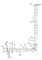
- the cartridge heater consists essentially of the angle tube 1, the horizontal leg of which is designated 2 and the vertical leg of which is 3.
- the angle piece 4 is inserted between the horizontal leg 2 and the vertical leg 3.
- the vertical leg 3 is closed at its upper end by the pressure-encapsulated connection head 5.
- the heater 6 is mounted in the horizontal leg 2 of the angled tube 1 and is surrounded by a liquid filling, preferably water, which extends into the vertical leg 3.
- a liquid filling preferably water
- connection head 5 a pipe piece 8 is attached to the side of the vertical leg 3, which is equipped with two series-connected, independently operating pressure switches 9, which are provided with a reference symbol for the sake of simplicity.
- a filling valve 10 is connected to the pipe section 8.
- the heater 6 is installed in the horizontal leg 2 by means of centering disks 11 such that it is always surrounded by a liquid jacket.
- a base plate 16 On the horizontal leg 2 of the angled tube 1, a base plate 16 is attached to its outer end, an earth connection 17 being provided between the latter and the free end of the heating element 6.
- a mounting flange 12 is welded, at such a height that it is always outside of zone 0, that is, in the area of zone 1, the arrangement being such that the pipe section 8 with the two Pressure switches 9 and the filling valve 10 are always located between the mounting flange 12 and the connection head 5.
- the pressure-tight seal between the flameproof enclosure Connection head 5 and the closed system which must always be above the pressure monitoring or above the filling valve, is produced by a pressure-tight welded-in bushing plate 13, into which a pressure-tight, not shown cable bushing with a thread is screwed tight.
- connection of the radiator 6 to the pressure-tight cable bushing is carried out with core cables which are connected to the radiator 6 in a watertight manner using shrink tubes 14.
- the test voltage against ground is 2 kV, for example.
- connection point on the outside of the connection head 5 The necessary equipotential bonding must be ensured via the connection point on the outside of the connection head 5.
Landscapes
- Engineering & Computer Science (AREA)
- Architecture (AREA)
- Civil Engineering (AREA)
- Structural Engineering (AREA)
- Instantaneous Water Boilers, Portable Hot-Water Supply Apparatuses, And Control Of Portable Hot-Water Supply Apparatuses (AREA)
Applications Claiming Priority (2)
| Application Number | Priority Date | Filing Date | Title |
|---|---|---|---|
| DE3932223 | 1989-09-27 | ||
| DE19893932223 DE3932223A1 (de) | 1989-09-27 | 1989-09-27 | Elektrischer patronenheizkoerper |
Publications (1)
| Publication Number | Publication Date |
|---|---|
| EP0420094A1 true EP0420094A1 (de) | 1991-04-03 |
Family
ID=6390293
Family Applications (1)
| Application Number | Title | Priority Date | Filing Date |
|---|---|---|---|
| EP90118290A Withdrawn EP0420094A1 (de) | 1989-09-27 | 1990-09-24 | Elektrischer Patronenheizkörper |
Country Status (2)
| Country | Link |
|---|---|
| EP (1) | EP0420094A1 (enExample) |
| DE (1) | DE3932223A1 (enExample) |
Cited By (1)
| Publication number | Priority date | Publication date | Assignee | Title |
|---|---|---|---|---|
| WO1998055711A1 (de) * | 1997-06-06 | 1998-12-10 | Reinhold Mennecke | Vorrichtung zur dachentwässerung, insbesondere dachrinne mit fallrohr und/oder rinneneisen |
Families Citing this family (1)
| Publication number | Priority date | Publication date | Assignee | Title |
|---|---|---|---|---|
| DE102007041983A1 (de) * | 2007-09-05 | 2009-03-12 | Ziemek Cable Technology Gmbh | Verfahren zum Betreiben einer elektrischen Heizanordnung |
Citations (3)
| Publication number | Priority date | Publication date | Assignee | Title |
|---|---|---|---|---|
| US2455102A (en) * | 1947-03-22 | 1948-11-30 | Wiegand Co Edwin L | Electric heating unit |
| US2469801A (en) * | 1945-12-03 | 1949-05-10 | Hotpoint Inc | Electric heater |
| US3141955A (en) * | 1962-04-12 | 1964-07-21 | Abner A Culpepper | Device for effecting water-flow from a roof or the like |
Family Cites Families (3)
| Publication number | Priority date | Publication date | Assignee | Title |
|---|---|---|---|---|
| DD36722A (enExample) * | ||||
| FR2483726A1 (fr) * | 1980-05-30 | 1981-12-04 | Cetal | Thermoplongeur utilisable en atmosphere explosible pour le chauffage de milieux liquides ou gazeux |
| DE8212850U1 (de) * | 1982-05-04 | 1982-09-23 | Wegner, Joachim, 4100 Duisburg | Heizvorrichtung fuer trinkgefaess-spuelbehaelter |
-
1989
- 1989-09-27 DE DE19893932223 patent/DE3932223A1/de active Granted
-
1990
- 1990-09-24 EP EP90118290A patent/EP0420094A1/de not_active Withdrawn
Patent Citations (3)
| Publication number | Priority date | Publication date | Assignee | Title |
|---|---|---|---|---|
| US2469801A (en) * | 1945-12-03 | 1949-05-10 | Hotpoint Inc | Electric heater |
| US2455102A (en) * | 1947-03-22 | 1948-11-30 | Wiegand Co Edwin L | Electric heating unit |
| US3141955A (en) * | 1962-04-12 | 1964-07-21 | Abner A Culpepper | Device for effecting water-flow from a roof or the like |
Cited By (1)
| Publication number | Priority date | Publication date | Assignee | Title |
|---|---|---|---|---|
| WO1998055711A1 (de) * | 1997-06-06 | 1998-12-10 | Reinhold Mennecke | Vorrichtung zur dachentwässerung, insbesondere dachrinne mit fallrohr und/oder rinneneisen |
Also Published As
| Publication number | Publication date |
|---|---|
| DE3932223A1 (de) | 1991-04-04 |
| DE3932223C2 (enExample) | 1991-07-18 |
Similar Documents
| Publication | Publication Date | Title |
|---|---|---|
| EP3229242B1 (de) | Hochspannungsdurchführung | |
| DE102009014334B4 (de) | Stromanschlusseinrichtung für Behälter | |
| EP0420094A1 (de) | Elektrischer Patronenheizkörper | |
| DE3103299C2 (de) | Abdichtung für Leitungsdurchführungen | |
| DE2550601C2 (de) | Vorrichtung zur elektrischen Behandlung einer Öl als kontinuierliche Phase enthaltenden Emulsion | |
| DE8700714U1 (de) | Wanddurchführung für Rohre oder Kabel | |
| DE3220945A1 (de) | Schweissstellenfreie verbindung | |
| DE60104788T2 (de) | Gasisolierter Leistungsschalter mit integriertem elektronischem Stromwandler | |
| DE2758192A1 (de) | Druckfeste heizstabdurchfuehrung fuer ein fluessiges, verdampfbares medium enthaltende druckbehaelter, vorzugsweise fuer druckhalter von kernreaktoranlagen | |
| DE1230115B (de) | Hochspannungsschaltanlage mit druckgasisoliertem Schaltgeraet | |
| DE2743057A1 (de) | Endverschluss fuer elektrische hochspannungsdruckkabel, insbesondere gasaussendruckkabel | |
| DE19616885C2 (de) | Verfahren zur Montage einer Stichleitung mit einem zusätzlichen Innenrohr und Anordnung zur Durchführung der Montage | |
| DE3904495C2 (enExample) | ||
| DE3209974C2 (de) | Elektrische Isoliertrennstelle einer Gas-Rohrleitung | |
| DE2609512A1 (de) | Gasisolierte thyristoranordnung | |
| EP0826991B1 (de) | Gasdichte Lichtleiterkupplung | |
| DE2725461C3 (de) | Vorrichtung zum Aufbau einer Prüfstation zum Überwachen unterirdisch verlegter Prüfdrähte | |
| DE2420888C3 (de) | Säulenartige Schleifringanordnung für den Wähler und Anzapfumsteller von Stufenschaltern für Transformatoren | |
| DE3106160A1 (de) | Rohrpassstueck | |
| DE3842647A1 (de) | Kuehlwasserrohr | |
| WO2026002478A1 (de) | Verfahren und vorrichtung zum zusammenbau eines transformators mit direktkühlung | |
| DE7729689U1 (de) | Endverschluß für elektrische Hochspannungsdruckkabel, insbesondere Gasaußendruckkabel | |
| DE3100863A1 (de) | Leitungsabdichtung | |
| EP0073049A1 (de) | Gebäudeeinführung für Versorgungsleitungen, insbesondere für Gas und Wasser | |
| EP0902347B1 (de) | Gasdruckregelgerät |
Legal Events
| Date | Code | Title | Description |
|---|---|---|---|
| PUAI | Public reference made under article 153(3) epc to a published international application that has entered the european phase |
Free format text: ORIGINAL CODE: 0009012 |
|
| AK | Designated contracting states |
Kind code of ref document: A1 Designated state(s): AT BE CH DE DK ES FR GB GR IT LI LU NL SE |
|
| 17P | Request for examination filed |
Effective date: 19910821 |
|
| 17Q | First examination report despatched |
Effective date: 19930219 |
|
| STAA | Information on the status of an ep patent application or granted ep patent |
Free format text: STATUS: THE APPLICATION IS DEEMED TO BE WITHDRAWN |
|
| 18D | Application deemed to be withdrawn |
Effective date: 19940401 |