EP0420019A2 - Extrudiermatrize mit langgestreckter Extrusionsdüse, welche Werkzeugwechsel vereinfacht - Google Patents
Extrudiermatrize mit langgestreckter Extrusionsdüse, welche Werkzeugwechsel vereinfacht Download PDFInfo
- Publication number
- EP0420019A2 EP0420019A2 EP90118003A EP90118003A EP0420019A2 EP 0420019 A2 EP0420019 A2 EP 0420019A2 EP 90118003 A EP90118003 A EP 90118003A EP 90118003 A EP90118003 A EP 90118003A EP 0420019 A2 EP0420019 A2 EP 0420019A2
- Authority
- EP
- European Patent Office
- Prior art keywords
- extrusion
- core
- die
- upstream
- downstream
- Prior art date
- Legal status (The legal status is an assumption and is not a legal conclusion. Google has not performed a legal analysis and makes no representation as to the accuracy of the status listed.)
- Granted
Links
Images


Classifications
-
- B—PERFORMING OPERATIONS; TRANSPORTING
- B29—WORKING OF PLASTICS; WORKING OF SUBSTANCES IN A PLASTIC STATE IN GENERAL
- B29C—SHAPING OR JOINING OF PLASTICS; SHAPING OF MATERIAL IN A PLASTIC STATE, NOT OTHERWISE PROVIDED FOR; AFTER-TREATMENT OF THE SHAPED PRODUCTS, e.g. REPAIRING
- B29C48/00—Extrusion moulding, i.e. expressing the moulding material through a die or nozzle which imparts the desired form; Apparatus therefor
- B29C48/25—Component parts, details or accessories; Auxiliary operations
- B29C48/36—Means for plasticising or homogenising the moulding material or forcing it through the nozzle or die
- B29C48/50—Details of extruders
- B29C48/695—Flow dividers, e.g. breaker plates
- B29C48/70—Flow dividers, e.g. breaker plates comprising means for dividing, distributing and recombining melt flows
-
- B—PERFORMING OPERATIONS; TRANSPORTING
- B29—WORKING OF PLASTICS; WORKING OF SUBSTANCES IN A PLASTIC STATE IN GENERAL
- B29C—SHAPING OR JOINING OF PLASTICS; SHAPING OF MATERIAL IN A PLASTIC STATE, NOT OTHERWISE PROVIDED FOR; AFTER-TREATMENT OF THE SHAPED PRODUCTS, e.g. REPAIRING
- B29C48/00—Extrusion moulding, i.e. expressing the moulding material through a die or nozzle which imparts the desired form; Apparatus therefor
- B29C48/001—Combinations of extrusion moulding with other shaping operations
- B29C48/0013—Extrusion moulding in several steps, i.e. components merging outside the die
- B29C48/0015—Extrusion moulding in several steps, i.e. components merging outside the die producing hollow articles having components brought in contact outside the extrusion die
-
- B—PERFORMING OPERATIONS; TRANSPORTING
- B29—WORKING OF PLASTICS; WORKING OF SUBSTANCES IN A PLASTIC STATE IN GENERAL
- B29C—SHAPING OR JOINING OF PLASTICS; SHAPING OF MATERIAL IN A PLASTIC STATE, NOT OTHERWISE PROVIDED FOR; AFTER-TREATMENT OF THE SHAPED PRODUCTS, e.g. REPAIRING
- B29C48/00—Extrusion moulding, i.e. expressing the moulding material through a die or nozzle which imparts the desired form; Apparatus therefor
- B29C48/03—Extrusion moulding, i.e. expressing the moulding material through a die or nozzle which imparts the desired form; Apparatus therefor characterised by the shape of the extruded material at extrusion
- B29C48/09—Articles with cross-sections having partially or fully enclosed cavities, e.g. pipes or channels
-
- B—PERFORMING OPERATIONS; TRANSPORTING
- B29—WORKING OF PLASTICS; WORKING OF SUBSTANCES IN A PLASTIC STATE IN GENERAL
- B29C—SHAPING OR JOINING OF PLASTICS; SHAPING OF MATERIAL IN A PLASTIC STATE, NOT OTHERWISE PROVIDED FOR; AFTER-TREATMENT OF THE SHAPED PRODUCTS, e.g. REPAIRING
- B29C48/00—Extrusion moulding, i.e. expressing the moulding material through a die or nozzle which imparts the desired form; Apparatus therefor
- B29C48/16—Articles comprising two or more components, e.g. co-extruded layers
- B29C48/18—Articles comprising two or more components, e.g. co-extruded layers the components being layers
- B29C48/21—Articles comprising two or more components, e.g. co-extruded layers the components being layers the layers being joined at their surfaces
-
- B—PERFORMING OPERATIONS; TRANSPORTING
- B29—WORKING OF PLASTICS; WORKING OF SUBSTANCES IN A PLASTIC STATE IN GENERAL
- B29C—SHAPING OR JOINING OF PLASTICS; SHAPING OF MATERIAL IN A PLASTIC STATE, NOT OTHERWISE PROVIDED FOR; AFTER-TREATMENT OF THE SHAPED PRODUCTS, e.g. REPAIRING
- B29C48/00—Extrusion moulding, i.e. expressing the moulding material through a die or nozzle which imparts the desired form; Apparatus therefor
- B29C48/25—Component parts, details or accessories; Auxiliary operations
- B29C48/30—Extrusion nozzles or dies
- B29C48/303—Extrusion nozzles or dies using dies or die parts movable in a closed circuit, e.g. mounted on movable endless support
-
- B—PERFORMING OPERATIONS; TRANSPORTING
- B29—WORKING OF PLASTICS; WORKING OF SUBSTANCES IN A PLASTIC STATE IN GENERAL
- B29C—SHAPING OR JOINING OF PLASTICS; SHAPING OF MATERIAL IN A PLASTIC STATE, NOT OTHERWISE PROVIDED FOR; AFTER-TREATMENT OF THE SHAPED PRODUCTS, e.g. REPAIRING
- B29C48/00—Extrusion moulding, i.e. expressing the moulding material through a die or nozzle which imparts the desired form; Apparatus therefor
- B29C48/25—Component parts, details or accessories; Auxiliary operations
- B29C48/30—Extrusion nozzles or dies
- B29C48/32—Extrusion nozzles or dies with annular openings, e.g. for forming tubular articles
- B29C48/34—Cross-head annular extrusion nozzles, i.e. for simultaneously receiving moulding material and the preform to be coated
-
- B—PERFORMING OPERATIONS; TRANSPORTING
- B29—WORKING OF PLASTICS; WORKING OF SUBSTANCES IN A PLASTIC STATE IN GENERAL
- B29C—SHAPING OR JOINING OF PLASTICS; SHAPING OF MATERIAL IN A PLASTIC STATE, NOT OTHERWISE PROVIDED FOR; AFTER-TREATMENT OF THE SHAPED PRODUCTS, e.g. REPAIRING
- B29C48/00—Extrusion moulding, i.e. expressing the moulding material through a die or nozzle which imparts the desired form; Apparatus therefor
- B29C48/25—Component parts, details or accessories; Auxiliary operations
- B29C48/30—Extrusion nozzles or dies
- B29C48/32—Extrusion nozzles or dies with annular openings, e.g. for forming tubular articles
Definitions
- the invention relates to apparatus comprising means for extruding parison having an annular cross-section and a mold tunnel for the parison.
- Such apparatus may comprise, for example, an extrusion nozzle for thermoplastic material and a mold tunnel of the travelling type, for example, for continuously molding thermoplastic tube.
- the apparatus may be suitable for the production of various types of tube, e.g. single walled, double walled, corrugated ribbed and combinations thereof, etc.
- Such apparatus conventionally comprises a hollow core extending longitudinally through the extrusion nozzle, into the mold tunnel and extending rearwardly through the extrusion head.
- a hollow core may act as an inner mandrel about which extrudate flows in an annular channel defined between the core and the outer casing of an extrusion nozzle.
- Extrudate may be introduced into the channel by a lateral opening thereinto and/or by an axial opening thereinto or when more than one channel is provided for plastic flow, by either or both lateral or axial openings.
- the core performs various important functions. Within its hollow interior, it may carry pipes carrying blowing air to press the parison against the mold tunnel, pipes carrying cooling fluid to cool and help set thermoplastic parison located against the mold tunnel, pipes carrying heating fluid, if desired, pipes carrying suction for application to the inner surface of the parison, if desired, pipes carrying lubricant, hydraulic fluid, etc.
- the outside of the core may carry a forming plug located within the mold tunnel for forming the interior surface of the parison and maintaining its shape until the thermoplastic material is sufficiently set to retain it shape without assistance.
- a plug may be a cooling plug to aid setting of the thermoplastic material. It may be lubricated at its surface, may have applied suction at its surface, may provide other services at its surface from service pipes within the core.
- a heating plug and follower plugs may, in some circumstances also be carried by the core.
- various aids for pressing the pipe into the corrugators of the mold tunnel may be carried by the core.
- the core may carry at least one spider to carry services from the core to the interior of an outer parison and/or as a spacer for annular channels of the extrusion nozzle.
- the core may carry an inner die lip defining, with an outer lip an extrusion orifice opening for an angled exit passage the geometry of which is of considerable importance in different applications.
- the upstream end of the cooling plug may be shaped to form the appropriate angle for the exit passage.
- At the downstream end of the core means may be provided to allow for slight longitudinal movement to adjust, for example, the width of the exit passage and means may also be provided to inhibit twisting of the core, there causing torsion of the parison.
- the outer casing of the extrusion nozzle may be coaxial with the core and assembled with the extrusion head downstream thereof.
- the outer casing of the extrusion nozzle carries shaping die lips which often flare outwardly from the general diameter of the extrusion nozzle.
- a hollow mandrel is present intermediate between the outer casing of the extrusion nozzle ano the inner core and coaxial with them.
- This mandrel also carries die lips at its extrusion orifice.
- the core may carry parts on its outer surface, which parts may be of greater diameter than the core itself, and because the outer casing of the extrusion nozzle is attached to the extrusion head downstream thereof, has not been easy to withdraw the core and extrusion nozzle from the apparatus.
- the inventor has attempted to devise an arrangement to allow for improved facility in accessing the components downstream of the extrusion head in this respect a novel approach has been taken in that the possibility of withdrawing the core with the extrusion nozzle from the apparatus in a downstream direction was investigated.
- This has not previously been possible due to the structure of cores which conventionally have a stop flange upstream of the extrusion head for locating the core in proper position.
- cores are illustrated in, for example U.S. Patent No. 4,712,993 and U.S. No. 4770, 618 both issued to Lupke on December 15, 1987 and September 13th, 1988 respectively.
- Other cases have been provided with keying arrangements to allow limited axial motion of the core without rotation. Such keying arrangements are also illustrated in the above noted patents and would, even without the stop flange, prevent full withdrawal of the core in the downstream direction.
- an intermediate mandrel When an intermediate mandrel is present to define two annular channels within the extrusion nozzle for the production of double walled tubing, it may, together with a coaxial channel in the extrusion head, be tapered to reduce in diameter in the downstream direction thus precluding any possibility of withdrawal of this component in a downstream direction.
- a coaxial channel in the extrusion head Such an arrangement is illustrated in both the previously referred to U.S. patents.
- an extrusion die for apparatus for producing seamless thermoplastic tubing including; an extrusion head having a bore therethrough and at least one input port to the bore for thermoplastic extrudate; an elongate extrusion nozzle releasably attached to the extrusion head to extend the bore longitudinally in a downstream direction for extrudate; an elongate hollow core of diameter not exceeding that of the bore, extending coaxially through the bore, the core having an upstream portion upstream of the input port and extending out of the bore in the upstream direction, and a downstream portion forming a mandrel coaxial within the extrusion nozzle and projecting therefrom; the upstream core portion being attached to the extrusion head through an upstream threaded core end releasably engaged with a correspondingly threaded collar which is also attachable to the extrusion head.
- connection between the elongate extrusion nozzle and the extrusion head may be by screw threading between a nozzle collar of the extrusion head and a upstream end of the extrusion nozzle.
- the core and the extrusion nozzle may define a single annular channel between them for the production of single walled tube or a hollow mandrel may be provided coaxially intermediate the core and the elongate extrusion nozzle, thereby providing a further coaxial annular extrusion passage for the production of double walled tubing.
- the mandrel may separate plastic material flow from each of two extruders or it may separate the flow from a single extruders
- the hollow mandrel may be releasably attached to the extrusion head by means of threading between a mandrel collar of the extrusion head and an upstream end of the hollow mandrel for flow from two extruders. For dividing the flow from a single extruder, a downstream end of the mandrel may be supported by a spider.
- the core may be attached to the extrusion head through screw threaded attachment with a core collar bolted to the extrusion head.
- any upstream attachment to the core such as a closing plug, possibly carrying upstream equipment may be attached to the core through an axial female socket of the upstream core end.
- the downstream portion of the core may carry a forming plug in a mold tunnel.
- the core may carry inner annular die lips to direct extrudate outwardly from the core and the mandrel respectively towards a molding surface of a mold tunnel.
- the downstream end of the extrusion nozzle carries a disengageable outer annular die lip to cooperate with the inner die lip of the core to direct extrudate outwardly therebetween.
- the inner die lip of the core may be formed by the suitably formed upstream front surface of the forming plug so that the extrudate extrudes directly onto the plug.
- the plug may be a cooling plug.
- an intermediate mandrel When an intermediate mandrel is present it may carry at its downstream end an outer die lip cooperating with an inner die lip of the core, e.g. the cooling plug and further upstream may carry an inner die lip cooperating with an outer die lip of the extrusion nozzle.
- the extrusion head may comprise a two part head, the one part including an first input channel usually to accept thermoplastic material from a first extruder and the other part including a second input channel usually to accept thermoplastic material from a second extruder.
- These extrusion head parts are usually arranged such that the first and second input channels are directed in diametrically opposite directions or at least angled to one another to allow for suitable location of the extruders.
- any intermediate mandrel and other fittings of the extrusion head are symmetrically located, it may be possible to provide the said extrusion head parts attachable together in a first position to connect first ano second extruders, or, alternatively in a second position so that they both access the same outlet of one extruder.
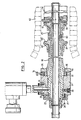
- Figures 1, 2 and 3 show extrusion dies for extrusion of single walled tube, double walled tube by splitting of the extrusion flow and double walled tube from two input ports respectively.
- like reference numerals are used for like parts where possible and differences between the apparatus are referred to where appropriate.
- the apparatus comprises an extrusion die having an inner core which acts as an inner mandrel the inner core 10 is attached to an extrusion head 12 and extends in a bore within the extrusion head 12.
- the apparatus of Figures 1 and 2 have a single inlet 14 for extrudate of thermoplastic material for forming seamless tube.
- the extrudate from inlet 14 passes into an annular passage 16 between the inner core 10 an extrusion nozzle 18 surrounding the inner core 10.
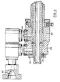
- the apparatus of Figures 3 and 4 have two inlets for extrudate 114 and 115.
- a hollow mandrel 120 is located coaxially about the inner core 10 within the extrusion nozzle 18 so as to form two annular extrusion channels 116 and 117.
- hollow mandrel 120 The upstream end of hollow mandrel 120 is located and shaped so that extrudate from inlet Port 114 flow in annular channel 116 and extrudate from inlet port 115 flow in annular channel 117.
- a coaxial hollow mandrel 20 surrounds hollow core lu to divide the flow of extrudate in channel 16 into an inner continuing channel 26 and exiting outer exit channel 36.
- the upstream end of the inner cores the intermediate hollow mandrel, and the extrusion nozzle 18 may be provided with integral or fixed radially outwardly extending collars which may be bolted onto the extrusion heads. Such collars prevent the withdrawal of the inner core 10, the intermediate mandrel or the extrusion nozzle through the extrusion head. In the case of extrusion nozzle, this may not be particularly important, but for accessing tools on the inner core or on the intermediate mandrel, it may be necessary to dismantle the extrusion head to change tools thereon.
- Figures 1, 2 and 3 of the drawings show a new arrangement for the connection of the inner core 10, the intermediate mandrel 120, and the extrusion nozzle 18. In all cases, the diameter of the core 10 is no greater than the diameter of the bore of the extrusion head 12.
- the core is provided with screw threading 22 on an upstream portion which extends out of the bore of extrusion head 12 in the upstream direction.
- a collar 24 has an inner surface with corresponding screw threading by which it is releasably engageable with the core.
- the collar 24 also has a radially extending flange 25 by which it may bolted to the extrusion head 12.
- the core may be closed at the upstream end by a plug 26 which may carry connections for services to extend within the core, such as vacuum lines for air, gas carrying lines or fluid carrying lines for blowing air or for heating or cooling purposes, hydraulic lines, etc.
- the plug may carry other upstream tools if desired.
- the plug is connected with the core through internal screw threading 28 on an female axial end socket of the core. This socket corresponds with a fitting, similarly screw threaded male member of the plug.
- the extrusion nozzle 18 Downstream of the extrusion head, the extrusion nozzle 18 may be connected to the downstream side of the extrusion head in a somewhat similar manner.
- An outer surface of an upstream end of the extrusion nozzle 18 is provided with screw threading 30 to releasably engage a nozzle collar 32 which fits loosely in a recess in the extrusion head in which it may be centered by centering screws 34.
- a radially extending second collar 36 which overlaps the nozzle collar 32 may be bolted to the extrusion head 12 to hold the assembly in place.
- the extrusion nozzle may be released simply from the extrusion head by unbolting collar 36 and unscrewing extrusion head from nozzle collar 32.
- centering of the core may be achieved through centering screw 38 but this is somewhat limited due to the bolts necessary between collar 24 and the extrusion head 12.
- the downstream end of the extrusion nozzle may be provided with an annular die lip 40.
- the die lip may be attached to the extrusion nozzle by simple screw threading 42 as shown by which it is easily releasable and, when the core 10 is withdrawn, replaceable by a different die lip. Other means of attachment of the die lip are possible for its axial adjustment on extrusion nozzle 10 or for its replacement.
- the outer die lip 40 and other die lips to be described hereinafter or the extrusion nozzle may be provided with a further member to bear on the die lips or lip to slide it into a different position.
- the inner die lip 54 Downstream of die lips 40 is an inner die lip 54. As shown in Figure 1, the inner die lip is formed by the frustoconical upstream end of a cooling plug 56.
- the cooling plug 56 acts to form the inside surface of the tube in an advancing mold tunnel of conventional design.
- Figure 2 shows an intermediate mandrel 20 dividing the extrudate passage 16 into two.
- the extrusion nozzle ends at die lips 40 which may be similar to those previously described and the upstream end of the mandrel 20 is shaped to form, or is provided with, inner die lips 58.
- the mandrel 20 itself is supported on a spider mechanism 60 which may serve to carry service lines, for example a line carrying blowing air, from the interior of inner core 10 to produce pressurized atmosphere for forcing extrudate from exit passage 37 against the walls of an advancing mold tunnel 62.
- the spider 60 may, of course, carry other services anu is generally used to support the mandrel.
- the intermediate mandrel 20 may be a one piece mandrel or might possibly be a two piece mandrel joined at spider 60 whereby independent adjustment of the upstream portion and the downstream portions of the mandrel 20 are possible.
- the downstream portion of mandrel 20 may carry die lips 39 similar to those described in connection with die lips 40. This die lip at the end of mandrel 20 cooperates with inner die lips 41 on the inner core 10. As before, these inner die lips 41 may be a frustoconical nose portion of cooling plug 56.
- FIG. 3 shows a very similar situation to that of Figure 2 except that intermediate mandrel 120 extends into extrusion head 12 to separate two input ports 15, 17 and direct them into annular channel 116 and 117 respectively.
- Inner die lips 70 may be provided at an appropriate point on intermediate mandrel 120 to cooperate with outer die lips 40 of extrusion nozzle 18.
- the downstream end of mandrel 120 is similar to that described for mandrel 20.
- Figure 3 shows the case where input channels 114, 115 connect two separate extruders 214, 215 respectively via the extrusion head 12 to the extrusion nozzle 18.
- Figure 4 shows a detail of such apparatus in which the input channels 114, 115 are arranged differently.
- Extrusion head 12 may be provided in two axially connecting parts 212, 213 which may be attached one to the other in different configurations.
- Figure 3 shows one configuration for different extruders 215, 217.
- Figure 4 shows a diametrically opposite configuration for connection to the single passage of a single extruder 217.
Applications Claiming Priority (2)
| Application Number | Priority Date | Filing Date | Title |
|---|---|---|---|
| CA000613930A CA1319478C (en) | 1989-09-28 | 1989-09-28 | Extrusion die having elongated extrusion nozzle which facilitates tool changes |
| CA613930 | 1989-09-28 |
Publications (3)
| Publication Number | Publication Date |
|---|---|
| EP0420019A2 true EP0420019A2 (de) | 1991-04-03 |
| EP0420019A3 EP0420019A3 (en) | 1991-06-19 |
| EP0420019B1 EP0420019B1 (de) | 1994-11-23 |
Family
ID=4140747
Family Applications (1)
| Application Number | Title | Priority Date | Filing Date |
|---|---|---|---|
| EP90118003A Expired - Lifetime EP0420019B1 (de) | 1989-09-28 | 1990-09-19 | Extrudiermatrize mit langgestreckter Extrusionsdüse, welche Werkzeugwechsel vereinfacht |
Country Status (4)
| Country | Link |
|---|---|
| US (1) | US5123827A (de) |
| EP (1) | EP0420019B1 (de) |
| CA (1) | CA1319478C (de) |
| DE (1) | DE69014268T2 (de) |
Cited By (6)
| Publication number | Priority date | Publication date | Assignee | Title |
|---|---|---|---|---|
| DE4111228A1 (de) * | 1991-04-08 | 1992-10-15 | Wilhelm Hegler | Vorrichtung zur herstellung von kunststoff-rohren |
| WO1992022417A1 (en) * | 1991-06-17 | 1992-12-23 | Corma Inc. | Extrusion die with interchangeable extrusion nozzles |
| WO1994009964A1 (en) * | 1992-10-30 | 1994-05-11 | Lupke Manfred Arno Alfred | Extrusion equipment having means for adjusting a delivery end of a die with respect to the extruder for alignment with downstream equipment |
| US5489201A (en) * | 1993-04-15 | 1996-02-06 | Cullom Machine Tool & Die, Inc. | Plastic tile corrugator and mold blocks |
| WO2000007801A1 (de) * | 1998-08-04 | 2000-02-17 | Unicor Gmbh Rahn Plastmaschinen | Vorrichtung zur kontinuierlichen herstellung von nahtlosen kunststoffrohren |
| DE10117126C1 (de) * | 2001-04-06 | 2002-08-01 | Unicor Rohrsysteme Gmbh | Vorrichtung zur Herstellung von Doppelwand-Wellrohren |
Families Citing this family (10)
| Publication number | Priority date | Publication date | Assignee | Title |
|---|---|---|---|---|
| DE4111229A1 (de) * | 1991-04-08 | 1992-10-15 | Wilhelm Hegler | Vorrichtung zur herstellung von kunststoff-rohren |
| DE4210482A1 (de) * | 1992-03-31 | 1993-10-07 | Wilhelm Hegler | Verfahren und Vorrichtung zur fortlaufenden Herstellung eines Verbundrohres mit Rohr-Muffe |
| US5545369A (en) * | 1993-09-08 | 1996-08-13 | Corma, Inc. | Clamshell corrugators and the like |
| US5466402A (en) * | 1994-05-13 | 1995-11-14 | Corma Inc. | Gap adjustment of a plastic flow channel in a plastic part forming device |
| US5846575A (en) * | 1997-03-17 | 1998-12-08 | Lupke; Manfred A. A. | Pipe forming mandrel with multiple sleeve inner tube |
| US7074027B2 (en) * | 2001-02-19 | 2006-07-11 | Starita Joseph M | Extrusion die and method for forming dual wall corrugated plastic pipe and dual wall plastic pipe having a foam annular core |
| GB2433180B (en) * | 2005-12-09 | 2008-01-30 | Oracle Int Corp | Communications method |
| CA2588058C (en) * | 2007-05-08 | 2014-07-15 | Stefan A. Lupke | Alignable cooling plug for extruder |
| US7841850B2 (en) * | 2007-10-22 | 2010-11-30 | Soheyl Mottahedeh | Method and apparatus for shaping thermoplastic profiles |
| WO2015137930A1 (en) * | 2014-03-11 | 2015-09-17 | Empire Technology Development Llc | Extrusion nozzles, methods, and systems for three dimensional printing |
Citations (5)
| Publication number | Priority date | Publication date | Assignee | Title |
|---|---|---|---|---|
| NL270677A (de) * | 1900-01-01 | |||
| GB941127A (en) * | 1961-03-24 | 1963-11-06 | Kunststoffmaschinen A G | Improved method and device for producing hollow bodies from thermoplastic synthetic material |
| US3546743A (en) * | 1968-04-26 | 1970-12-15 | Northern Petro Chem Co | Die for extruding laminated plastic tube |
| US4770618A (en) * | 1986-01-15 | 1988-09-13 | Lupke Manfred Arno Alfred | Extrusion die for two-ply plastic tubing |
| US4789327A (en) * | 1988-02-25 | 1988-12-06 | Harry Chan | Adjustable pipe extrusion die with internal cooling |
Family Cites Families (6)
| Publication number | Priority date | Publication date | Assignee | Title |
|---|---|---|---|---|
| US3357051A (en) * | 1967-01-09 | 1967-12-12 | Gnii Plasticheskykh Mass | Die for extrusion of double-wall of "tube-in-tube" type |
| AT325299B (de) * | 1967-02-27 | 1975-10-10 | Hegler Wilhelm | Vorrichtung zur herstellung von rohren aus thermoplastischem kunststoff |
| US3471899A (en) * | 1967-03-16 | 1969-10-14 | Cupples Container Co | Extrusion die |
| US3856446A (en) * | 1971-04-23 | 1974-12-24 | Electric Hose Rubber Co | Lead extrusion device with means for removing a die member without inactivating the material feed means |
| US4712993A (en) * | 1986-03-25 | 1987-12-15 | Lupke Manfred Arno Alfred | Extrusion die for externally ribbed plastic tubing |
| US4798526A (en) * | 1986-07-17 | 1989-01-17 | General Electric Company | Modular extrusion head |
-
1989
- 1989-09-28 CA CA000613930A patent/CA1319478C/en not_active Expired - Lifetime
-
1990
- 1990-09-11 US US07/580,879 patent/US5123827A/en not_active Expired - Lifetime
- 1990-09-19 EP EP90118003A patent/EP0420019B1/de not_active Expired - Lifetime
- 1990-09-19 DE DE69014268T patent/DE69014268T2/de not_active Expired - Lifetime
Patent Citations (6)
| Publication number | Priority date | Publication date | Assignee | Title |
|---|---|---|---|---|
| NL270677A (de) * | 1900-01-01 | |||
| GB941127A (en) * | 1961-03-24 | 1963-11-06 | Kunststoffmaschinen A G | Improved method and device for producing hollow bodies from thermoplastic synthetic material |
| US3546743A (en) * | 1968-04-26 | 1970-12-15 | Northern Petro Chem Co | Die for extruding laminated plastic tube |
| US4770618A (en) * | 1986-01-15 | 1988-09-13 | Lupke Manfred Arno Alfred | Extrusion die for two-ply plastic tubing |
| US4789327A (en) * | 1988-02-25 | 1988-12-06 | Harry Chan | Adjustable pipe extrusion die with internal cooling |
| US4789327B1 (en) * | 1988-02-25 | 2000-07-18 | Corma Inc | Adjustable pipe extrusion die with internal cooling |
Non-Patent Citations (1)
| Title |
|---|
| MODERN PLASTICS INTERNATIONAL, vol. 14, no. 12, December 1984, page 25, Lausanne, CH; New diehead reduces set-up times in sheating extrusion" * |
Cited By (15)
| Publication number | Priority date | Publication date | Assignee | Title |
|---|---|---|---|---|
| US5346384A (en) * | 1991-04-08 | 1994-09-13 | Wilhelm Hegler | Apparatus for the production of plastic pipes |
| EP0509216A2 (de) * | 1991-04-08 | 1992-10-21 | Wilhelm Hegler | Vorrichtung zur Herstellung von Kunststoff-Rohren |
| DE4111228A1 (de) * | 1991-04-08 | 1992-10-15 | Wilhelm Hegler | Vorrichtung zur herstellung von kunststoff-rohren |
| EP0509216A3 (en) * | 1991-04-08 | 1993-03-17 | Wilhelm Hegler | Device for the manufacturing of plastic tubes |
| US5576032A (en) * | 1991-06-17 | 1996-11-19 | Lupke; Manfred A. A. | Extrusion die with interchangeable extrusion nozzles |
| WO1992022417A1 (en) * | 1991-06-17 | 1992-12-23 | Corma Inc. | Extrusion die with interchangeable extrusion nozzles |
| WO1994009964A1 (en) * | 1992-10-30 | 1994-05-11 | Lupke Manfred Arno Alfred | Extrusion equipment having means for adjusting a delivery end of a die with respect to the extruder for alignment with downstream equipment |
| US6050805A (en) * | 1992-10-30 | 2000-04-18 | Lupke; Manfred | Extrusion equipment having means for adjusting a delivery end of a die with respect to the extruder for alignment with downstream equipment |
| US5489201A (en) * | 1993-04-15 | 1996-02-06 | Cullom Machine Tool & Die, Inc. | Plastic tile corrugator and mold blocks |
| US5494430A (en) * | 1993-04-15 | 1996-02-27 | Cullom Machine Tool & Die, Inc. | Plastic tube corrugator with mold blocks |
| US5531583A (en) * | 1993-04-15 | 1996-07-02 | Cullom Machine Tool & Die, Inc. | Vacuum mold blocks with cooling for corrugated tubing |
| US5645871A (en) * | 1993-04-15 | 1997-07-08 | Cullom Machine Tool & Die, Inc. | Plastic tile corrugator and mold blocks |
| WO2000007801A1 (de) * | 1998-08-04 | 2000-02-17 | Unicor Gmbh Rahn Plastmaschinen | Vorrichtung zur kontinuierlichen herstellung von nahtlosen kunststoffrohren |
| US6616437B1 (en) | 1998-08-04 | 2003-09-09 | Unicor Gmbh Rahn Plastmaschinen | Device for continuously producing seamless plastic tubes |
| DE10117126C1 (de) * | 2001-04-06 | 2002-08-01 | Unicor Rohrsysteme Gmbh | Vorrichtung zur Herstellung von Doppelwand-Wellrohren |
Also Published As
| Publication number | Publication date |
|---|---|
| EP0420019A3 (en) | 1991-06-19 |
| DE69014268T2 (de) | 1995-07-06 |
| CA1319478C (en) | 1993-06-29 |
| EP0420019B1 (de) | 1994-11-23 |
| US5123827A (en) | 1992-06-23 |
| DE69014268D1 (de) | 1995-01-05 |
Similar Documents
| Publication | Publication Date | Title |
|---|---|---|
| US5123827A (en) | Extrusion die having elongated extrusion nozzle with facilitates tool changes | |
| EP0230055B1 (de) | Extruderdüse zur Herstellung zwei-schichtiger Rohrleitungen | |
| EP0048112B1 (de) | Strangpresskopf-Anordnung für thermoplastische Schläuche | |
| US4808098A (en) | Pipe extrusion die with a cooled and vacuumed additional mandrel | |
| CA1309564C (en) | Adjustable pipe extrusion die with internal cooling | |
| US4889477A (en) | Extruder head | |
| CA1320323E (en) | Extrusion die for externally ribbed plastic tubing | |
| CA1053426A (en) | Multiple extrusion apparatus | |
| EP0670768B1 (de) | Extrudereinrichtung mit mitteln zur anpassung des abgabenendes einer extrusionsdüse relativ zu einem extruder zur ausrichtung einer stromabwärts liegenden vorrichtung | |
| KR940006644B1 (ko) | 압출다이 어셈블리 | |
| US3932102A (en) | Spiral design pipehead | |
| US20080131542A1 (en) | Device for extruding hollow strands | |
| US4936768A (en) | Extrusion die for externally ribbed plastic tubing | |
| US3311952A (en) | Extrusion die for blown film | |
| US5576032A (en) | Extrusion die with interchangeable extrusion nozzles | |
| CN116423790A (zh) | 一种管中管成型模具及方法 | |
| CN210233937U (zh) | 一种气体辅助薄壁小截面管材挤出成型模具 | |
| CA2658408C (en) | Method and apparatus for continuous manufacture of a compound pipe comprising a pipe socket | |
| US10583596B2 (en) | Injection head for an apparatus for the production of a twin-wall pipe | |
| CN220429222U (zh) | 光缆护套挤塑装置 | |
| CN214056352U (zh) | 叠加式挤出成型模具 | |
| CN220700338U (zh) | 一种挤出模具模口结构 | |
| CN217573985U (zh) | 气辅冷却成型的pvc给水管材高速挤出模具 | |
| CN213412830U (zh) | 一种用于管材挤出的口模结构 | |
| CN218535561U (zh) | 一种管材的挤出生产模具 |
Legal Events
| Date | Code | Title | Description |
|---|---|---|---|
| PUAI | Public reference made under article 153(3) epc to a published international application that has entered the european phase |
Free format text: ORIGINAL CODE: 0009012 |
|
| AK | Designated contracting states |
Kind code of ref document: A2 Designated state(s): DE FR GB NL |
|
| PUAL | Search report despatched |
Free format text: ORIGINAL CODE: 0009013 |
|
| AK | Designated contracting states |
Kind code of ref document: A3 Designated state(s): DE FR GB NL |
|
| 17P | Request for examination filed |
Effective date: 19911017 |
|
| 17Q | First examination report despatched |
Effective date: 19930323 |
|
| GRAA | (expected) grant |
Free format text: ORIGINAL CODE: 0009210 |
|
| AK | Designated contracting states |
Kind code of ref document: B1 Designated state(s): DE FR GB NL |
|
| REF | Corresponds to: |
Ref document number: 69014268 Country of ref document: DE Date of ref document: 19950105 |
|
| ET | Fr: translation filed | ||
| PLBE | No opposition filed within time limit |
Free format text: ORIGINAL CODE: 0009261 |
|
| STAA | Information on the status of an ep patent application or granted ep patent |
Free format text: STATUS: NO OPPOSITION FILED WITHIN TIME LIMIT |
|
| 26N | No opposition filed | ||
| REG | Reference to a national code |
Ref country code: GB Ref legal event code: IF02 |
|
| PGFP | Annual fee paid to national office [announced via postgrant information from national office to epo] |
Ref country code: GB Payment date: 20090929 Year of fee payment: 20 Ref country code: NL Payment date: 20090924 Year of fee payment: 20 |
|
| PGFP | Annual fee paid to national office [announced via postgrant information from national office to epo] |
Ref country code: DE Payment date: 20090929 Year of fee payment: 20 |
|
| REG | Reference to a national code |
Ref country code: NL Ref legal event code: V4 Effective date: 20100919 |
|
| REG | Reference to a national code |
Ref country code: GB Ref legal event code: PE20 Expiry date: 20100918 |
|
| PG25 | Lapsed in a contracting state [announced via postgrant information from national office to epo] |
Ref country code: GB Free format text: LAPSE BECAUSE OF EXPIRATION OF PROTECTION Effective date: 20100918 |
|
| PG25 | Lapsed in a contracting state [announced via postgrant information from national office to epo] |
Ref country code: NL Free format text: LAPSE BECAUSE OF EXPIRATION OF PROTECTION Effective date: 20100919 |
|
| PGFP | Annual fee paid to national office [announced via postgrant information from national office to epo] |
Ref country code: FR Payment date: 20091006 Year of fee payment: 20 |
|
| PG25 | Lapsed in a contracting state [announced via postgrant information from national office to epo] |
Ref country code: DE Free format text: LAPSE BECAUSE OF EXPIRATION OF PROTECTION Effective date: 20100919 |