EP0419888A1 - Pneumatic boat with increased inner space - Google Patents
Pneumatic boat with increased inner space Download PDFInfo
- Publication number
- EP0419888A1 EP0419888A1 EP90116829A EP90116829A EP0419888A1 EP 0419888 A1 EP0419888 A1 EP 0419888A1 EP 90116829 A EP90116829 A EP 90116829A EP 90116829 A EP90116829 A EP 90116829A EP 0419888 A1 EP0419888 A1 EP 0419888A1
- Authority
- EP
- European Patent Office
- Prior art keywords
- boat
- shell
- inflatable
- inner space
- inflatable boat
- Prior art date
- Legal status (The legal status is an assumption and is not a legal conclusion. Google has not performed a legal analysis and makes no representation as to the accuracy of the status listed.)
- Granted
Links
Images
Classifications
-
- B—PERFORMING OPERATIONS; TRANSPORTING
- B63—SHIPS OR OTHER WATERBORNE VESSELS; RELATED EQUIPMENT
- B63B—SHIPS OR OTHER WATERBORNE VESSELS; EQUIPMENT FOR SHIPPING
- B63B7/00—Collapsible, foldable, inflatable or like vessels
- B63B7/06—Collapsible, foldable, inflatable or like vessels having parts of non-rigid material
- B63B7/08—Inflatable
- B63B7/082—Inflatable having parts of rigid material
Definitions
- the invention relates to an inflatable boat with a boat shell and an essentially U-shaped tubular body on the outside of the boat shell in a plan view.
- Inflatable boats of this type have become known in numerous embodiments, the invention relating in particular to inflatable boats in which the boat shell consists of glass-fiber reinforced plastic. It is common to the known inflatable boats that the tubular body has a circular cross section.
- the object of the invention is to propose such an inflatable boat in which the usable interior of the inflatable boat is appreciably enlarged.
- the invention is characterized in that the tube body is flattened in cross section at least in the region of the legs of the U on its inside facing the boat shell.
- the flattening should result in an approximately crescent-shaped profile, as is also shown in the drawing.
- other profiles are also conceivable, for example a straight end, although a profile which is slightly flattened on the inside, for example as shown in the drawing, is preferred in particular for reasons of fastening between the hose body and the boat shell.
- the desired profiling of the hose body is preferably achieved in that appropriately profiled bulkheads or terminations are inserted into and connected to the hose body.
- the connection is preferably made by gluing.
- the bulkheads can be made of flexible material.
- the endings are preferably made of hard material, for example wooden disks.
- the equipment of an inflatable boat with a vertical or oblique hose end is known per se and is also used in the inflatable boat according to the invention.
- connection between the boat shell and the hose body will be formed as an adhesive connection.
- a shell-shaped adhesive surface is provided on the side of the hull facing the hose body, the underside of which can be designed as a stringer strip.
- the stringer bar can additionally stabilize the driving behavior of the inflatable boat.
- the bowl-shaped adhesive surface is bent upwards again by a shorter distance in order to better surround the hose body and to achieve a particularly good adhesive connection.
- the invention is explained in more detail below on the basis of an exemplary embodiment from which further important features result.
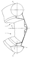
- the figure schematically shows a section through an inflatable boat, the left half of the figure representing an inflatable boat according to the invention and the right half for comparison a conventional inflatable boat.
- a boat shell 1 made of glass fiber reinforced plastic is provided, which ends on the outside in a shell-shaped adhesive surface 2.
- the adhesive surface is profiled such that a tubular body 3 with an approximately crescent-shaped profile is connected to the boat shell 1. This profile is achieved by appropriately profiled bulkheads and end caps, which are inserted into the tube body 3 and glued to it are.
- the hose closure consists of a rigid part made of wood, plastic, for example hard PVC, molded part made of GRP or steel, and spaced apart from one another, at least one corresponding partition, preferably made of suitable flexible material, is inserted into the hose body in the hose body on the left and right.
- the crescent-shaped tube body is then pressed onto the correspondingly constructed boat shell 1 and glued in the conventional manner.
- This design creates an additional stringer strip 4 on the underside, which can positively influence the driving behavior of the inflatable boat when driving straight ahead and when cornering.
- a comparison of the left half of the figure with the right half shows that the interior on the left is perceptibly larger than the interior on the right. This is due to the fact that in the conventional inflatable boat, as indicated on the right in the figure, the tubular body 5 is profiled in a circular manner. (The two halves in the figure are separated from one another by an imaginary center line 6).
- the hose body 3 has essentially the shape of a U, which tapers somewhat in the middle, corresponding to the usual shape of such inflatable boats.
- the described profiling of the hose body 3 is now provided according to the invention at least on the two sides of the hose body, ie on the two legs of the U, but preferably on the entire hose body.
Abstract
Description
Die Erfindung betrifft ein Schlauchboot mit einer Bootsschale und einem in einer Draufsicht im wesentlichen U-förmigen Schlauchkörper an der Außenseite der Bootsschale.The invention relates to an inflatable boat with a boat shell and an essentially U-shaped tubular body on the outside of the boat shell in a plan view.
Derartige Schlauchboote sind in zahlreichen Ausführungsformen bekannt geworden, wobei die Erfindung sich insbesondere auf Schlauchboote bezieht, bei denen die Bootsschale aus glasfaserverstärktem Kunststoff besteht. Den bekannten Schlauchbooten ist es gemeinsam, daß der Schlauchkörper einen kreisförmigen Querschnitt hat.Inflatable boats of this type have become known in numerous embodiments, the invention relating in particular to inflatable boats in which the boat shell consists of glass-fiber reinforced plastic. It is common to the known inflatable boats that the tubular body has a circular cross section.
Demgegenüber liegt der Erfindung die Aufgabe zugrunde, ein derartiges Schlauchboot vorzuschlagen, bei dem der nutzbare Innenraum des Schlauchboots fühlbar vergrößert ist.In contrast, the object of the invention is to propose such an inflatable boat in which the usable interior of the inflatable boat is appreciably enlarged.
Zur Lösung dieser Aufgabe ist die Erfindung dadurch gekennzeichnet, daß der Schlauchkörper im Querschnitt zumindest im Bereich der Schenkel des U an seiner zur Bootsschale weisenden Innenseite abgeflacht ist.To achieve this object, the invention is characterized in that the tube body is flattened in cross section at least in the region of the legs of the U on its inside facing the boat shell.
Durch diese Abflachung gewinnt man entsprechenden Platz, der als Innenraum des Schlauchboots genutzt werden kann.This flattening gives you the appropriate space that can be used as the interior of the inflatable boat.
Die Abflachung soll ein etwa halbmondförmiges Profil ergeben, wie dies auch zeichnerisch dargestellt ist. Das heisst, daß das Profil des Schlauchkörpers an seiner Innenseite mit einem verhältnismässig großen Radius nach innen gewölbt verläuft. Es sind aber auch andere Profilierungen denkbar, beispielsweise ein gerader Abschluß, obgleich insbesondere aus Gründen der Befestigung zwischen dem Schlauchkörper und der Bootsschale ein an der Innenseite leicht abgeflachtes Profil, etwa wie zeichnerisch dargestellt, bevorzugt wird.The flattening should result in an approximately crescent-shaped profile, as is also shown in the drawing. This means that the profile of the tube body is curved on the inside with a relatively large radius. However, other profiles are also conceivable, for example a straight end, although a profile which is slightly flattened on the inside, for example as shown in the drawing, is preferred in particular for reasons of fastening between the hose body and the boat shell.
Die angestrebte Profilierung des Schlauchkörpers wird vorzugsweise dadurch erreicht, daß entsprechend profilierte Schotten bzw. Abschlüsse in den Schlauchkörper eingesetzt und mit diesem verbunden sind. Die Verbindung erfolgt vorzugsweise durch eine Verklebung. Die Schotten können aus flexiblem Material bestehen. Die Abschlüsse bestehen vorzugsweise aus hartem Material, beispielsweise Holzscheiben. Die Ausrüstung eines Schlauchboots mit einem senkrechten oder schrägen Schlauchabschluß ist ansich bekannt und wird auch bei dem erfindungsgemässen Schlauchboot verwendet.The desired profiling of the hose body is preferably achieved in that appropriately profiled bulkheads or terminations are inserted into and connected to the hose body. The connection is preferably made by gluing. The bulkheads can be made of flexible material. The endings are preferably made of hard material, for example wooden disks. The equipment of an inflatable boat with a vertical or oblique hose end is known per se and is also used in the inflatable boat according to the invention.
Die Verbindung zwischen der Bootsschale und dem Schlauchkörper wird man als Klebeverbindung ausbilden. Zu diesem Zweck ist an der zum Schlauchkörper weisenden Seite des Bootskörpers eine schalenförmige Klebefläche vorgesehen, deren Unterseite als Stringerleiste ausgebildet werden kann. Die Stringerleiste kann das Fahrverhalten des Schlauchboots zusätzlich stabilisieren. Im Bereich der Stringerleiste ist die schalenförmige Klebefläche um einen kürzeren Abstand wieder nach oben gebogen zwecks besserer Einfassung des Schlauchkörpers und zur Erzielung einer besonders guten Klebeverbindung.The connection between the boat shell and the hose body will be formed as an adhesive connection. For this purpose, a shell-shaped adhesive surface is provided on the side of the hull facing the hose body, the underside of which can be designed as a stringer strip. The stringer bar can additionally stabilize the driving behavior of the inflatable boat. In the area of the stringer strip, the bowl-shaped adhesive surface is bent upwards again by a shorter distance in order to better surround the hose body and to achieve a particularly good adhesive connection.
Die Erfindung wird im folgenden anhand eines Ausführungsbeispiels näher erläutert, aus dem sich weitere wichtige Merkmale ergeben. Die Figur zeigt schematisch einen Schnitt durch ein Schlauchboot, wobei die linke Hälfte der Figur ein erfindungsgemässes Schlauchboot darstellt und die rechte Hälfte zum Vergleich ein herkömmliches Schlauchboot.The invention is explained in more detail below on the basis of an exemplary embodiment from which further important features result. The figure schematically shows a section through an inflatable boat, the left half of the figure representing an inflatable boat according to the invention and the right half for comparison a conventional inflatable boat.
Es ist eine Bootsschale 1 aus glasfaserverstärktem Kunststoff vorgesehen, der aussen in einer schalenförmigen Klebefläche 2 endet.A boat shell 1 made of glass fiber reinforced plastic is provided, which ends on the outside in a shell-shaped adhesive surface 2.
Die Klebefläche ist so profiliert, daß ein Schlauchkörper 3 mit etwa halbmondförmigem Profil mit der Bootsschale 1 verbunden wird. Dieses Profil wird durch entsprechend profilierte Schotten und Abschlüsse erreicht, die in den Schlauchkörper 3 eingesetzt und mit diesem verklebt sind. Der Schlauchabschluß besteht aus einem starren Teil aus Holz, Kunststoff, z.B. Hart PVC, Formteil aus GFK oder Stahl, und beabstandet voneinander sind im Schlauchkörper links und rechts mindestens jeweils ein entsprechendes Schott, vorzugsweise aus geeignetem flexiblen Material, in den Schlauchkörper eingesetzt.The adhesive surface is profiled such that a
Der halbmondförmige Schlauchkörper wird dann an die entsprechend konstruierte Bootsschale 1 angepresst und nach herkömmlicher Art verklebt.The crescent-shaped tube body is then pressed onto the correspondingly constructed boat shell 1 and glued in the conventional manner.
Durch diese Konstruktionsweise entsteht an der Unterseite eine zusätzliche Stringerleiste 4, die das Fahrverhalten des Schlauchboots bei Geradeausfahrt und bei Kurvenfahrt positiv beeinflussen kann.This design creates an additional stringer strip 4 on the underside, which can positively influence the driving behavior of the inflatable boat when driving straight ahead and when cornering.
Ein Vergleich der linken Hälfte der Figur mit der rechten Hälfte zeigt, daß der Innenraum links fühlbar größer ist als der Innenraum rechts. Dies beruht darauf, daß bei dem herkömmlichen Schlauchboot, wie es rechts in der Figur angedeutet ist, der Schlauchkörper 5 kreisförmig profiliert ist. (Die beiden Hälften in der Figur werden durch eine gedachte Mittellinie 6 voneinander getrennt).A comparison of the left half of the figure with the right half shows that the interior on the left is perceptibly larger than the interior on the right. This is due to the fact that in the conventional inflatable boat, as indicated on the right in the figure, the tubular body 5 is profiled in a circular manner. (The two halves in the figure are separated from one another by an imaginary center line 6).
In einer Draufsicht hat der Schlauchkörper 3 im wesentlichen die Form eines U, welches in der Mitte etwas spitz zuläuft, entsprechend der üblichen Form derartiger Schlauchboote. Die beschriebene Profilierung des Schlauchkörpers 3 ist nun erfindungsgemäss zumindest an den beiden Seiten des Schlauchkörpers, d.h. an den beiden Schenkeln des U, vorgesehen, vorzugsweise aber am gesamten Schlauchkörper.In a plan view, the
- 1 Bootsschale1 boat shell
- 2 Klebefläche2 adhesive surfaces
- 3 Schlauchkörper3 hose body
- 4 Stringerleiste4 stringer bar
- 5 Schlauchkörper5 hose body
- 6 Mittellinie6 center line
Claims (3)
Priority Applications (1)
| Application Number | Priority Date | Filing Date | Title |
|---|---|---|---|
| AT90116829T ATE98586T1 (en) | 1989-09-27 | 1990-09-01 | INFLATABLE BOAT WITH ENLARGED INTERIOR. |
Applications Claiming Priority (2)
| Application Number | Priority Date | Filing Date | Title |
|---|---|---|---|
| DE3932132A DE3932132A1 (en) | 1989-09-27 | 1989-09-27 | INFLATABLE BOAT WITH ENLARGED INTERIOR |
| DE3932132 | 1989-09-27 |
Publications (2)
| Publication Number | Publication Date |
|---|---|
| EP0419888A1 true EP0419888A1 (en) | 1991-04-03 |
| EP0419888B1 EP0419888B1 (en) | 1993-12-15 |
Family
ID=6390236
Family Applications (1)
| Application Number | Title | Priority Date | Filing Date |
|---|---|---|---|
| EP90116829A Expired - Lifetime EP0419888B1 (en) | 1989-09-27 | 1990-09-01 | Pneumatic boat with increased inner space |
Country Status (3)
| Country | Link |
|---|---|
| EP (1) | EP0419888B1 (en) |
| AT (1) | ATE98586T1 (en) |
| DE (2) | DE3932132A1 (en) |
Cited By (3)
| Publication number | Priority date | Publication date | Assignee | Title |
|---|---|---|---|---|
| GB2363762A (en) * | 2000-06-21 | 2002-01-09 | Tiger Marine Ltd | Boat with a rigid hull and a shaped buoyant collar |
| WO2012007694A1 (en) * | 2010-07-13 | 2012-01-19 | Zodiac International | Improvement to boats having inflatable planking |
| FR3066751A1 (en) * | 2017-05-29 | 2018-11-30 | Zodiac Milpro International | INFLATABLE BOAT WITH CONFORMING WALL IN D |
Citations (3)
| Publication number | Priority date | Publication date | Assignee | Title |
|---|---|---|---|---|
| GB980705A (en) * | 1961-03-08 | 1965-01-20 | Otto Hanel | Improvements in or relating to inflatable boats |
| US3168751A (en) * | 1961-06-01 | 1965-02-09 | Hutchinson Cie Ets | Pneumatic boat |
| FR2471545A1 (en) * | 1979-12-13 | 1981-06-19 | Hennebutte Georges | Inflatable envelope for aircraft wing or float - has rigid plaques installed to form specific shapes and adhered to interior during manufacture |
Family Cites Families (12)
| Publication number | Priority date | Publication date | Assignee | Title |
|---|---|---|---|---|
| DE7112075U (en) * | 1971-07-22 | Menges E | Two elements sailing dinghy | |
| US2223625A (en) * | 1939-04-01 | 1940-12-03 | Krupp Herman | Pneumatic boat |
| AT180860B (en) * | 1953-09-16 | 1955-01-25 | Semperit Ag | Inflatable boat with several inflatable tubes forming the boat wall |
| DE1808224U (en) * | 1959-10-14 | 1960-03-17 | Luwefa Kunststoffverarbeitung | BOAT. |
| AT229172B (en) * | 1961-03-08 | 1963-08-26 | Otto Hanel Kg | dinghy |
| DE1901947U (en) * | 1964-07-01 | 1964-10-08 | Alfred Drexler | Airtight bulkhead for especially inflatable inflatable boats or. DGL. |
| DE1903374U (en) * | 1964-08-21 | 1964-10-29 | Metzeler Ag | INFLATABLE BOAT WITH SEVERAL SHEETS OF RUBBER FABRIC OD. DGL. SEPARATE COMPRESSED AIR CELLS. |
| FR2370626A1 (en) * | 1976-11-15 | 1978-06-09 | Sevylor | INFLATABLE BOAT |
| GB2161118B (en) * | 1984-07-02 | 1988-06-22 | Avon Ind Polymers | Improved inflatable tube boat |
| DE3507353A1 (en) * | 1985-03-01 | 1986-09-04 | Metzeler Kautschuk GmbH, 8000 München | SPORTS BOAT |
| FR2578220A1 (en) * | 1985-03-04 | 1986-09-05 | Croatto Bernard | Rigid boat with a high degree of stability making it possible to transport heavy loads |
| US4807554A (en) * | 1987-02-27 | 1989-02-28 | Intex Recreation Corp. | Inflatable boat for high speed applications |
-
1989
- 1989-09-27 DE DE3932132A patent/DE3932132A1/en not_active Withdrawn
-
1990
- 1990-09-01 DE DE90116829T patent/DE59003867D1/en not_active Expired - Fee Related
- 1990-09-01 AT AT90116829T patent/ATE98586T1/en not_active IP Right Cessation
- 1990-09-01 EP EP90116829A patent/EP0419888B1/en not_active Expired - Lifetime
Patent Citations (3)
| Publication number | Priority date | Publication date | Assignee | Title |
|---|---|---|---|---|
| GB980705A (en) * | 1961-03-08 | 1965-01-20 | Otto Hanel | Improvements in or relating to inflatable boats |
| US3168751A (en) * | 1961-06-01 | 1965-02-09 | Hutchinson Cie Ets | Pneumatic boat |
| FR2471545A1 (en) * | 1979-12-13 | 1981-06-19 | Hennebutte Georges | Inflatable envelope for aircraft wing or float - has rigid plaques installed to form specific shapes and adhered to interior during manufacture |
Cited By (11)
| Publication number | Priority date | Publication date | Assignee | Title |
|---|---|---|---|---|
| GB2363762A (en) * | 2000-06-21 | 2002-01-09 | Tiger Marine Ltd | Boat with a rigid hull and a shaped buoyant collar |
| WO2012007694A1 (en) * | 2010-07-13 | 2012-01-19 | Zodiac International | Improvement to boats having inflatable planking |
| FR2962710A1 (en) * | 2010-07-13 | 2012-01-20 | Zodiac Int | IMPROVEMENT IN BOATS WITH INFLATABLE BORDERS |
| CN103180204A (en) * | 2010-07-13 | 2013-06-26 | 卓迪雅克·米尔普罗国际公司 | Improvement to boats having inflatable planking |
| JP2013530099A (en) * | 2010-07-13 | 2013-07-25 | ゾディアック ミルプロ アンテルナショナル | Improvements to boats with inflatable ship edges. |
| US8789486B2 (en) | 2010-07-13 | 2014-07-29 | Zodiac Milpro International | Boats having inflatable planking |
| AU2011278162B2 (en) * | 2010-07-13 | 2014-08-21 | Zodiac Milpro International | Improvement to boats having inflatable planking |
| CN103180204B (en) * | 2010-07-13 | 2016-04-13 | 卓迪雅克·米尔普罗国际公司 | The ship with inflatable boat coverboard improved |
| FR3066751A1 (en) * | 2017-05-29 | 2018-11-30 | Zodiac Milpro International | INFLATABLE BOAT WITH CONFORMING WALL IN D |
| WO2018219909A1 (en) * | 2017-05-29 | 2018-12-06 | Zodiac Milpro International | Inflatable boat with a d-shaped wall |
| US11091228B2 (en) | 2017-05-29 | 2021-08-17 | Zodiac Milpro International | Inflatable boat with D-shaped wall |
Also Published As
| Publication number | Publication date |
|---|---|
| EP0419888B1 (en) | 1993-12-15 |
| DE3932132A1 (en) | 1991-04-04 |
| ATE98586T1 (en) | 1994-01-15 |
| DE59003867D1 (en) | 1994-01-27 |
Similar Documents
| Publication | Publication Date | Title |
|---|---|---|
| DE3214876C2 (en) | ||
| DE647370C (en) | Railway car body | |
| EP0419888B1 (en) | Pneumatic boat with increased inner space | |
| EP1135271B1 (en) | Bow configuration | |
| DE2612117A1 (en) | ARTICULATED COUPLING PROFILE COMPONENT, IN PARTICULAR FOR VEHICLE BODIES | |
| DE7918705U1 (en) | SEALING FRAME | |
| DE19781984B4 (en) | Load carrier strut | |
| DE2907518A1 (en) | Catamaran has hollow hulls - with one-piece deck panel, all of grp., glued together and a built-in inter-hull spar housing | |
| DE2555845A1 (en) | Railway train coach concertina link - has flat finish cover over folds to exclude wind at high speeds | |
| DE3409760C1 (en) | Self-supporting inflatable boat | |
| EP0102006B1 (en) | Rubbing strake for inflatable boats | |
| DE2125316A1 (en) | Inflatable boat | |
| DE3019896C2 (en) | ||
| DE2604597A1 (en) | Reduced drag paddle for kayak - has concave profile plus longitudinal ribs and grooves for stability | |
| DE3321306A1 (en) | Motor vehicle trailer, preferably caravan | |
| DE1958267U (en) | PROFILE PART FOR EXTERIOR CLADDING, IN PARTICULAR ROOFING. | |
| DE1259714B (en) | Air cushion boundary wall made from a large number of inflatable components | |
| DE8014005U1 (en) | Bellows | |
| AT386384B (en) | MOTOR VEHICLE TIRES | |
| DE1024109B (en) | Device for the fixed connection of flexible wall parts for vehicles, in particular for a transition protection between two rail vehicles | |
| DE19922022A1 (en) | Pipe clamp with annular holder body and ends with flanges has hollow chambers and is highly efficient | |
| EP0537670A1 (en) | Bellows for connection of articulated vehicles | |
| DE3527370A1 (en) | INFLATABLE BOAT | |
| AT40105B (en) | Elastic wheel. | |
| DE3605029A1 (en) | Apparatus for covering water surfaces, in particular of swimming pools |
Legal Events
| Date | Code | Title | Description |
|---|---|---|---|
| PUAI | Public reference made under article 153(3) epc to a published international application that has entered the european phase |
Free format text: ORIGINAL CODE: 0009012 |
|
| AK | Designated contracting states |
Kind code of ref document: A1 Designated state(s): AT DE FR GB GR IT |
|
| 17P | Request for examination filed |
Effective date: 19910606 |
|
| 17Q | First examination report despatched |
Effective date: 19920515 |
|
| GRAA | (expected) grant |
Free format text: ORIGINAL CODE: 0009210 |
|
| AK | Designated contracting states |
Kind code of ref document: B1 Designated state(s): AT DE FR GB GR IT |
|
| PG25 | Lapsed in a contracting state [announced via postgrant information from national office to epo] |
Ref country code: IT Free format text: LAPSE BECAUSE OF FAILURE TO SUBMIT A TRANSLATION OF THE DESCRIPTION OR TO PAY THE FEE WITHIN THE PRE;WARNING: LAPSES OF ITALIAN PATENTS WITH EFFECTIVE DATE BEFORE 2007 MAY HAVE OCCURRED AT ANY TIME BEFORE 2007. THE CORRECT EFFECTIVE DATE MAY BE DIFFERENT FROM THE ONE RECORDED.SCRIBED TIME-LIMIT Effective date: 19931215 Ref country code: FR Effective date: 19931215 Ref country code: GR Free format text: LAPSE BECAUSE OF FAILURE TO SUBMIT A TRANSLATION OF THE DESCRIPTION OR TO PAY THE FEE WITHIN THE PRESCRIBED TIME-LIMIT Effective date: 19931215 Ref country code: GB Effective date: 19931215 |
|
| REF | Corresponds to: |
Ref document number: 98586 Country of ref document: AT Date of ref document: 19940115 Kind code of ref document: T |
|
| REF | Corresponds to: |
Ref document number: 59003867 Country of ref document: DE Date of ref document: 19940127 |
|
| EN | Fr: translation not filed | ||
| GBV | Gb: ep patent (uk) treated as always having been void in accordance with gb section 77(7)/1977 [no translation filed] |
Effective date: 19931215 |
|
| PG25 | Lapsed in a contracting state [announced via postgrant information from national office to epo] |
Ref country code: AT Effective date: 19940901 |
|
| PLBE | No opposition filed within time limit |
Free format text: ORIGINAL CODE: 0009261 |
|
| STAA | Information on the status of an ep patent application or granted ep patent |
Free format text: STATUS: NO OPPOSITION FILED WITHIN TIME LIMIT |
|
| 26N | No opposition filed | ||
| PG25 | Lapsed in a contracting state [announced via postgrant information from national office to epo] |
Ref country code: DE Effective date: 19950601 |