EP0418923A1 - Bumper assembly for vehicles - Google Patents
Bumper assembly for vehicles Download PDFInfo
- Publication number
- EP0418923A1 EP0418923A1 EP90118201A EP90118201A EP0418923A1 EP 0418923 A1 EP0418923 A1 EP 0418923A1 EP 90118201 A EP90118201 A EP 90118201A EP 90118201 A EP90118201 A EP 90118201A EP 0418923 A1 EP0418923 A1 EP 0418923A1
- Authority
- EP
- European Patent Office
- Prior art keywords
- bumper
- bumper reinforcement
- reinforcement
- vehicle body
- assembly according
- Prior art date
- Legal status (The legal status is an assumption and is not a legal conclusion. Google has not performed a legal analysis and makes no representation as to the accuracy of the status listed.)
- Granted
Links
Images


Classifications
-
- B—PERFORMING OPERATIONS; TRANSPORTING
- B60—VEHICLES IN GENERAL
- B60R—VEHICLES, VEHICLE FITTINGS, OR VEHICLE PARTS, NOT OTHERWISE PROVIDED FOR
- B60R19/00—Wheel guards; Radiator guards, e.g. grilles; Obstruction removers; Fittings damping bouncing force in collisions
- B60R19/02—Bumpers, i.e. impact receiving or absorbing members for protecting vehicles or fending off blows from other vehicles or objects
- B60R19/18—Bumpers, i.e. impact receiving or absorbing members for protecting vehicles or fending off blows from other vehicles or objects characterised by the cross-section; Means within the bumper to absorb impact
-
- B—PERFORMING OPERATIONS; TRANSPORTING
- B60—VEHICLES IN GENERAL
- B60R—VEHICLES, VEHICLE FITTINGS, OR VEHICLE PARTS, NOT OTHERWISE PROVIDED FOR
- B60R19/00—Wheel guards; Radiator guards, e.g. grilles; Obstruction removers; Fittings damping bouncing force in collisions
- B60R19/02—Bumpers, i.e. impact receiving or absorbing members for protecting vehicles or fending off blows from other vehicles or objects
- B60R19/24—Arrangements for mounting bumpers on vehicles
-
- B—PERFORMING OPERATIONS; TRANSPORTING
- B60—VEHICLES IN GENERAL
- B60R—VEHICLES, VEHICLE FITTINGS, OR VEHICLE PARTS, NOT OTHERWISE PROVIDED FOR
- B60R19/00—Wheel guards; Radiator guards, e.g. grilles; Obstruction removers; Fittings damping bouncing force in collisions
- B60R19/02—Bumpers, i.e. impact receiving or absorbing members for protecting vehicles or fending off blows from other vehicles or objects
- B60R19/18—Bumpers, i.e. impact receiving or absorbing members for protecting vehicles or fending off blows from other vehicles or objects characterised by the cross-section; Means within the bumper to absorb impact
- B60R2019/1806—Structural beams therefor, e.g. shock-absorbing
- B60R2019/1813—Structural beams therefor, e.g. shock-absorbing made of metal
- B60R2019/182—Structural beams therefor, e.g. shock-absorbing made of metal of light metal, e.g. extruded
-
- B—PERFORMING OPERATIONS; TRANSPORTING
- B60—VEHICLES IN GENERAL
- B60R—VEHICLES, VEHICLE FITTINGS, OR VEHICLE PARTS, NOT OTHERWISE PROVIDED FOR
- B60R19/00—Wheel guards; Radiator guards, e.g. grilles; Obstruction removers; Fittings damping bouncing force in collisions
- B60R19/02—Bumpers, i.e. impact receiving or absorbing members for protecting vehicles or fending off blows from other vehicles or objects
- B60R19/24—Arrangements for mounting bumpers on vehicles
- B60R2019/242—Arrangements for mounting bumpers on vehicles on two vertical sleeves, e.g. on energy absorber ends
Definitions
- This invention relates to a bumper assembly for automotive vehicles and, more particularly, to improvements in a bumper reinforcement and the sectional configuration of the bumper assembly.
- the bumper assembly includes a bumper reinforcement 1, an energy absorber 2 disposed on the load surface of the bumper reinforcement 1, and a bumper cover 3 covering the energy absorber 2 secured to the bumper reinforcement 1.
- the bumper assembly is secured, at the back face of the bumper reinforcement 1, to a side member 4 constituting part of the vehicle body.
- the bumper reinforcement 1 has a box-shaped configuration comprising a front wall 6 on which the load surface is formed, a rear wall 7 on which the back surface is formed, upper and lower walls 8, 9 connecting the front wall 6 and rear wall 7, and a horizontal intermediate wall 10 connecting the front wall 6 and rear wall 7.
- a problem with this bumper reinforcement 1 is that when the reinforcement is flexed and deformed by a load such as an impact load, a bending moment in a direction which impedes the flexural deformation is produced at the joint between the bumper reinforcement 1 and side member 4, as shown in Fig. 16, since the reinforcement 1 and side member 4 are in a fixed state. As a result, there is the danger that local deformation will occur in the upper and lower walls 8, 9 near the vicinity where the bumper reinforcement 1 is fixed to the side member 4.
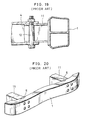
- FIG. 17 An example of the connecting means according to the prior art is shown in Fig. 17. Specifically, a bumper stay 11 secured to the back surface of the bumper reinforcement 1 is fitted into the side member 4, which constitutes part of the vehicle body, and the bumper stay 11 is fixedly connected to the side member 4 by a bolt 12.
- Another problem encountered in this bumper assembly is that when a load is applied in the direction of the arrow due to a collision or the like, as shown in Fig. 18, the bumper reinforcement 1 attempts to undergo flexural deformation, as indicated by the two-dot chain line, owing to the applied load. Since the bumper stay 11 and side member 4 are in a fixed state, a bending moment in a direction which impedes the flexural deformation is produced at the joint between the bumper stay 11 and side member 4. Consequently, there is the danger that local deformation 5 will occur where the bumper reinforcement 1 is fixed to the bumper stay 11, as illustrated in Figs. 19 and 20.
- an object of the present invention is to provide a bumper assembly in which local deformation of the upper and lower walls of the bumper reinforcement is eliminated.
- Another object of the present invention is to provide a bumper assembly adapted to reduce the bending moment produced in the direction which impedes flexural deformation of the bumper reinforcement.
- a vehicle bumper assembly comprising a pair of side members constituting part of a vehicle body, a bumper reinforcement supported on the side members and extending transversely of the vehicle body, and an energy absorber arranged on a front surface of the bumper reinforcement, the bumper reinforcement having a rectangular cross section, upper and lower walls, and an intermediate wall connecting the upper and lower walls.
- the buckling strength of the upper and lower walls can be increased, thereby making it possible to eliminate local deformation produced, at portions where the upper and lower walls are fixed to the vehicle body, by a bending moment which develops at the joints between the bumper reinforcement and the vehicle body owing to flexural deformation of the bumper reinforcement caused by impact or the like.
- the buckling strength of the upper and lower walls can be increased merely by providing the intermediate wall. As a result, the buckling strength of the upper and lower walls can be raised while maintaining the conventional rigidity of the bumper reinforcement without requiring an increase in the thickness of the upper and lower walls.
- the present invention provides a vehicle bumper assembly comprising a bumper reinforcement extending transversely of a vehicle body, an energy absorber arranged on a load surface of the bumper reinforcement, a bumper cover secured to the bumper reinforcement for covering the energy absorber, and a bumper stay secured to a back surface of the bumper reinforcement for connecting the bumper reinforcement to the vehicle body, the bumper stay having a columnar portion extending vertically of the bumper reinforcement, and the vehicle body having insertion holes matching the columnar portion and a connecting member passed through the columnar portion and the insertion holes for turnably connecting the bumper stay to the vehicle body.
- the bumper assembly according to this aspect of the invention is capable of reducing the bending moment that hinders flexural deformation of the bumper reinforcement produced at the joints between the bumper stay and the vehicle body, thus making it possible to prevent local deformation at portions where the bumper reinforcement is secured to the vehicle body. Since the flexural deformation of the bumper reinforcement can be increased, the energy absorbing capability of the bumper reinforcement is enhanced, thereby reducing the effects of a collision upon the vehicle body.
- the present invention further provides a vehicle bumper assembly comprising a bumper reinforcement extending transversely of a vehicle body, an energy absorber arranged on a load surface of the bumper reinforcement, a bumper cover secured to the bumper reinforcement for covering the energy absorber, the bumper reinforcement having a columnar bumper stay inserted into a through-hole disposed in upper and lower walls in the vicinity of a neutral axis of the bumper reinforcement, and the vehicle body having insertion holes matching a hollow portion of the columnar bumper stay, and a connecting member passed through the hollow portion and the insertion holes for turnably connecting the bumper stay to the vehicle body.
- a compressive load that impedes flexural deformation of the bumper reinforcement can be reduced.
- compressive stress can be reduced at the portions where the bumper reinforcement and bumper stay are fixed and near the center of the load surface of the bumper reinforcement.
- an energy absorber 2 is arranged on a load surface of a bumper reinforcement 13, and the absorber 2 is covered by a bumper cover 3 secured to the bumper reinforcement 13.
- the back surface of the bumper reinforcement 13 is fixedly fastened by a bolt 15 and nut 16 to a side member 14, which constitutes part of a vehicle body (not shown).
- the bumper reinforcement 13 has a box-shaped configuration comprising a front wall 20 on which the load surface is formed, a rear wall 21 on which the back surface is formed, and upper and lower walls 22, 23 connecting the front wall 20 and rear wall 21.
- the bumper reinforcement 13 is provided with an intermediate wall 24, which connects the upper wall 22 and lower wall 23.
- the intermediate wall 24 is located between the front and rear walls 20, 21 but is closer to the rear wall 21. Owing to this construction, the buckling strength of the upper wall 22 and lower wall 23 is raised.
- the buckling strength of the upper and lower walls 22, 23 can be increased merely by providing the intermediate wall 24, the buckling strength of the upper and lower walls 22, 23 can be raised while maintaining the conventional rigidity of the bumper reinforcement 13 without requiring an increase in the thickness of the upper and lower walls 22, 23.
- intermediate wall 24 can be provided substantially midway between the front and rear walls 20, 21, as depicted in Fig. 4.
- the bumper reinforcement 12 has a box-shaped configuration comprising the front wall 20 on which the load surface is formed, the rear wall 21 on which the back surface is formed, and the upper and lower walls 22, 23 connecting the front wall 20 and rear wall 21.
- the bumper reinforcement 13 is provided with the intermediate wall 24, which connects the upper wall 22 and lower wall 23.
- the intermediate wall 24 is located between the front and rear walls 20, 21 but is closer to the front wall 20. Owing to this construction, the buckling strength of the upper wall 22 and lower wall 23 is raised. This makes it possible to prevent local deformation of the upper and lower walls 22, 23 near the central portion of the bumper reinforcement 13 caused by compressive stress that increases due to concentration of load in the bumper reinforcement 13.
- compressive stress itself is capable of being reduced.
- the energy absorber 2 is arranged on the load surface of the bumper reinforcement 13, and the absorber 2 is covered by the bumper cover 3 secured to the bumper reinforcement 13.
- a bumper stay 25 is fastened to the back surface of the bumper reinforcement 13 by a bolt 26 and nut 27.
- a columnar portion 28 is joined as by welding to the bumper stay 25 and extends vertically of the bumper reinforcement 13 (vertically in Figs. 6 and 7).
- the upper and lower sides of a side member 29 constituting part of the vehicle body are formed to include respective flanges 29a that embrace the columnar portion 28 from its upper and lower ends.
- the flanges 29a are formed to have respective insertion holes 30 that match the columnar portion 28.
- a bolt 31 is passed through the columnar portion 28 and insertion holes 30 and is tightened by a nut 32, thereby connecting the bumper stay 25 and the side member 29.
- the bumper stay 25 is capable of turning, relative to the side member 29, about the bolt 31.
- the shape of the bumper reinforcement 13 is not limited to that of the present embodiment. Also, the means for fixing the bumper reinforcement 13 to the bumper stay 25 is not limited to that of the present embodiment.
- the columnar portion 28 can be joined to the bumper reinforcement 13 by being welded directly thereto.
- the columnar portion 28 can be integrated with the bumper stay 25 as by the extrusion molding of aluminum.
- the bumper reinforcement 13 can be assembled as by welding plates, as shown in Fig. 8.
- the bumper stay 25 is turnably connected to the side member 29 by the bolt 31. Therefore, even if the bumper stay 25 attempts to undergo flexural deformation owing to application of a load to the bumper reinforcement 13 by an impact such as a collision, turning of the bumper stay 25 releases this flexural deformation. Consequently, a bending moment that produces flexural deformation of the bumper reinforcement caused at the joints between the bumper stay 25 and the side member 29 can be reduced, thus making it possible to prevent local deformation at portions where the bumper reinforcement 13 is secured to the bumper stay 25. Since the flexural deformation of the bumper reinforcement can be increased, the energy absorbing capability of the bumper reinforcement 13 is enhanced, thereby reducing the effects of a collision upon the vehicle body.
- the energy absorber 2 is arranged on the load surface of a bumper reinforcement 13′, and the absorber 2 is covered by the bumper cover 3 secured to the bumper reinforcement 13′.
- the bumper reinforcement 13′ is formed to have a through-hole 33 in the vicinity of its neutral axis.
- a bumper stay 28 is arranged inside the through-hole 33.
- the bumper stay 28, which is columnar in shape, extends vertically of the bumper reinforcement 13′ (vertically in Figs. 10 and 11) and is formed to have a through-hole.
- the upper and lower sides of the side member 29 constituting part of the vehicle body are formed to include the respective flanges 29a that embrace the bumper stay 28.
- the flanges 29a are formed to have the respective insertion holes 30 that match the through-hole of the columnar portion 28.
- the bolt 31 is passed through this through-hole and the insertion holes 30 and is tightened by a nut 32, thereby connecting the bumper stay 28 and the side member 29.
- the bumper stay 28 is capable of turning, relative to the side member 29, about the bolt 31.
- the shape of the bumper reinforcement 13′ is not limited to that of the present embodiment.
- the through hole of the bumper stay 28 is made a threaded through-hole 140, bolts 170, 171 are screwed into the through-hole 140 from above and below, respectively, and the bolts 170, 171 are tightened.
- the bumper stay 28 comprises coaxially disposed nuts 130, 131. The bolts 170, 171 are screwed into the nuts 130, 131 from above and below, respectively, and the bolts 170, 171 are tightened.
- the bumper stay 28 is disposed near the neutral axis of the bumper reinforcement 13′, stretching of the bumper reinforcement 13′ is facilitated when a load acts upon the bumper reinforcement 13′ and the latter is flexurally deformed owing to impact caused by a collision or the like.
- a compressive load of the kind which hinders flexural deformation of the bumper reinforcement 13′ can be reduced.
- compressive stress at the portions where the bumper reinforcement 13′ is fixed to the bumper stay 28 and near the center of the load surface of the bumper reinforcement 13′ can be reduced, thereby preventing local deformation.
- the bumper stay 28 is turnably connected to the side member 29, flexural deformation of the bumper reinforcement 13′ can be facilitated by this turning motion, and a turning moment which hinders flexural deformation of the bumper reinforcement 13′ can also be reduced. This makes it possible to prevent local deformation, caused by a bending moment, at the portion where the bumper reinforcement 13′ is fixed to the bumper stay 28. Furthermore, since the flexural deformation of the bumper reinforcement 13′ can be increased, the energy absorbing capability of the bumper reinforcement 13′ is enhanced, thereby reducing the effects of a collision upon the vehicle body.
Abstract
Description
- This invention relates to a bumper assembly for automotive vehicles and, more particularly, to improvements in a bumper reinforcement and the sectional configuration of the bumper assembly.
- An example of a bumper assembly according to the prior art is as shown in Figs. 14 through 16. As illustrated in Fig. 14, the bumper assembly includes a
bumper reinforcement 1, an energy absorber 2 disposed on the load surface of thebumper reinforcement 1, and abumper cover 3 covering the energy absorber 2 secured to thebumper reinforcement 1. The bumper assembly is secured, at the back face of thebumper reinforcement 1, to aside member 4 constituting part of the vehicle body. Thebumper reinforcement 1 has a box-shaped configuration comprising afront wall 6 on which the load surface is formed, arear wall 7 on which the back surface is formed, upper andlower walls front wall 6 andrear wall 7, and a horizontalintermediate wall 10 connecting thefront wall 6 andrear wall 7. - A problem with this
bumper reinforcement 1 is that when the reinforcement is flexed and deformed by a load such as an impact load, a bending moment in a direction which impedes the flexural deformation is produced at the joint between thebumper reinforcement 1 andside member 4, as shown in Fig. 16, since thereinforcement 1 andside member 4 are in a fixed state. As a result, there is the danger that local deformation will occur in the upper andlower walls bumper reinforcement 1 is fixed to theside member 4. - The means for connecting the
reinforcement 1 and the side member will now be described. - An example of the connecting means according to the prior art is shown in Fig. 17. Specifically, a bumper stay 11 secured to the back surface of the
bumper reinforcement 1 is fitted into theside member 4, which constitutes part of the vehicle body, and thebumper stay 11 is fixedly connected to theside member 4 by abolt 12. - Another problem encountered in this bumper assembly is that when a load is applied in the direction of the arrow due to a collision or the like, as shown in Fig. 18, the
bumper reinforcement 1 attempts to undergo flexural deformation, as indicated by the two-dot chain line, owing to the applied load. Since the bumper stay 11 andside member 4 are in a fixed state, a bending moment in a direction which impedes the flexural deformation is produced at the joint between the bumper stay 11 andside member 4. Consequently, there is the danger thatlocal deformation 5 will occur where thebumper reinforcement 1 is fixed to thebumper stay 11, as illustrated in Figs. 19 and 20. - Accordingly, an object of the present invention is to provide a bumper assembly in which local deformation of the upper and lower walls of the bumper reinforcement is eliminated.
- Another object of the present invention is to provide a bumper assembly adapted to reduce the bending moment produced in the direction which impedes flexural deformation of the bumper reinforcement.
- According to the present invention, the foregoing objects are attained by providing a vehicle bumper assembly comprising a pair of side members constituting part of a vehicle body, a bumper reinforcement supported on the side members and extending transversely of the vehicle body, and an energy absorber arranged on a front surface of the bumper reinforcement, the bumper reinforcement having a rectangular cross section, upper and lower walls, and an intermediate wall connecting the upper and lower walls.
- With the bumper assembly of the present invention, the buckling strength of the upper and lower walls can be increased, thereby making it possible to eliminate local deformation produced, at portions where the upper and lower walls are fixed to the vehicle body, by a bending moment which develops at the joints between the bumper reinforcement and the vehicle body owing to flexural deformation of the bumper reinforcement caused by impact or the like. In addition, the buckling strength of the upper and lower walls can be increased merely by providing the intermediate wall. As a result, the buckling strength of the upper and lower walls can be raised while maintaining the conventional rigidity of the bumper reinforcement without requiring an increase in the thickness of the upper and lower walls.
- Further, the present invention provides a vehicle bumper assembly comprising a bumper reinforcement extending transversely of a vehicle body, an energy absorber arranged on a load surface of the bumper reinforcement, a bumper cover secured to the bumper reinforcement for covering the energy absorber, and a bumper stay secured to a back surface of the bumper reinforcement for connecting the bumper reinforcement to the vehicle body, the bumper stay having a columnar portion extending vertically of the bumper reinforcement, and the vehicle body having insertion holes matching the columnar portion and a connecting member passed through the columnar portion and the insertion holes for turnably connecting the bumper stay to the vehicle body.
- The bumper assembly according to this aspect of the invention is capable of reducing the bending moment that hinders flexural deformation of the bumper reinforcement produced at the joints between the bumper stay and the vehicle body, thus making it possible to prevent local deformation at portions where the bumper reinforcement is secured to the vehicle body. Since the flexural deformation of the bumper reinforcement can be increased, the energy absorbing capability of the bumper reinforcement is enhanced, thereby reducing the effects of a collision upon the vehicle body.
- The present invention further provides a vehicle bumper assembly comprising a bumper reinforcement extending transversely of a vehicle body, an energy absorber arranged on a load surface of the bumper reinforcement, a bumper cover secured to the bumper reinforcement for covering the energy absorber, the bumper reinforcement having a columnar bumper stay inserted into a through-hole disposed in upper and lower walls in the vicinity of a neutral axis of the bumper reinforcement, and the vehicle body having insertion holes matching a hollow portion of the columnar bumper stay, and a connecting member passed through the hollow portion and the insertion holes for turnably connecting the bumper stay to the vehicle body.
- In the bumper assembly according to this aspect of the invention, a compressive load that impedes flexural deformation of the bumper reinforcement can be reduced. As a result, compressive stress can be reduced at the portions where the bumper reinforcement and bumper stay are fixed and near the center of the load surface of the bumper reinforcement. This makes it possible to prevent local deformation. Since the bumper stay is turnably connected to the vehicle body, flexural deformation of the bumper reinforcement is facilitated by this turning motion, and the bending moment that impedes flexural deformation of the bumper reinforcement also can be reduced. Accordingly, local deformation, which is caused by the bending moment, at the portions where the bumper reinforcement is secured to the bumper stay can be prevented. Furthermore, since the flexural deformation of the bumper reinforcement can be increased, the energy absorbing capability of the bumper reinforcement is enhanced, thereby reducing the effects of a collision upon the vehicle body.
- Other features and advantages of the present invention will be apparent from the following description taken in conjunction with the accompanying drawings, in which like reference characters designate the same or similar parts throughout the figures thereof.
-
- Fig. 1 is a sectional view illustrating an embodiment of a vehicle bumper assembly according to the present invention;
- Fig. 2 is an exploded perspective view showing a connecting portion of the bumper assembly;
- Fig. 3 is a sectional view illustrating a bumper reinforcement;
- Fig. 4 is a sectional view corresponding to Fig. 3 and showing a second embodiment of the invention;
- Fig. 5 is a sectional view corresponding to Fig. 3 and showing a third embodiment of the invention;
- Fig. 6 is a sectional view illustrating means for connecting a bumper reinforcement and a side member in a fourth embodiment of a vehicle bumper assembly according to the present invention;
- Fig. 7 is an exploded perspective view of the principal components of Fig. 6;
- Figs. 8 and 9 are perspective views illustrating fifth and sixth embodiments of the invention;
- Fig. 10 is a sectional view illustrating a seventh embodiment of a vehicle bumper assembly according to the present invention;
- Fig. 11 is an exploded perspective view of the principal components of Fig. 10;
- Figs. 12 and 13 are sectional views corresponding to Fig. 10 and showing eighth and ninth embodiments of the invention;
- Figs. 14 through 16 are explanatory views illustrating an example of a vehicle bumper assembly according to the prior art; and
- Figs. 17 through 20 are explanatory views illustrating means for connecting a bumper reinforcement and a side member in a vehicle bumper assembly according to the prior art.
- Embodiments of the present invention will now be described in detail with reference to the drawings.
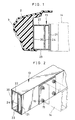
- As shown in Figs. 1 and 2, an
energy absorber 2 is arranged on a load surface of abumper reinforcement 13, and theabsorber 2 is covered by abumper cover 3 secured to thebumper reinforcement 13. The back surface of thebumper reinforcement 13 is fixedly fastened by abolt 15 andnut 16 to aside member 14, which constitutes part of a vehicle body (not shown). - As illustrated in Fig. 3, the
bumper reinforcement 13 has a box-shaped configuration comprising afront wall 20 on which the load surface is formed, arear wall 21 on which the back surface is formed, and upper andlower walls front wall 20 andrear wall 21. Thebumper reinforcement 13 is provided with anintermediate wall 24, which connects theupper wall 22 andlower wall 23. Theintermediate wall 24 is located between the front andrear walls rear wall 21. Owing to this construction, the buckling strength of theupper wall 22 andlower wall 23 is raised. Therefore, even if a bending moment is produced at the connection between thebumper reinforcement 12 and theside member 14 due to flexural deformation of thebumper reinforcement 13 caused by an impact such as a collision, local deformation will not occur at the portion where the upper and lower lowers 22, 23 are fixed to theside member 14. Since the buckling strength of the upper andlower walls intermediate wall 24, the buckling strength of the upper andlower walls bumper reinforcement 13 without requiring an increase in the thickness of the upper andlower walls - It should be noted that the
intermediate wall 24 can be provided substantially midway between the front andrear walls - In an embodiment shown in Fig. 5, the
bumper reinforcement 12 has a box-shaped configuration comprising thefront wall 20 on which the load surface is formed, therear wall 21 on which the back surface is formed, and the upper andlower walls front wall 20 andrear wall 21. Thebumper reinforcement 13 is provided with theintermediate wall 24, which connects theupper wall 22 andlower wall 23. Here theintermediate wall 24 is located between the front andrear walls front wall 20. Owing to this construction, the buckling strength of theupper wall 22 andlower wall 23 is raised. This makes it possible to prevent local deformation of the upper andlower walls bumper reinforcement 13 caused by compressive stress that increases due to concentration of load in thebumper reinforcement 13. In addition, since the neutral axis of the load ofbumper reinforcement 13 is shifted toward the side of thefront wall 20 by theintermediate wall 24, compressive stress itself is capable of being reduced. - As shown in Figs. 6 and 7 illustrating another embodiment of the present invention, the
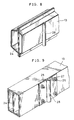
energy absorber 2 is arranged on the load surface of thebumper reinforcement 13, and theabsorber 2 is covered by thebumper cover 3 secured to thebumper reinforcement 13. Abumper stay 25 is fastened to the back surface of thebumper reinforcement 13 by abolt 26 andnut 27. Acolumnar portion 28 is joined as by welding to thebumper stay 25 and extends vertically of the bumper reinforcement 13 (vertically in Figs. 6 and 7). The upper and lower sides of aside member 29 constituting part of the vehicle body are formed to includerespective flanges 29a that embrace thecolumnar portion 28 from its upper and lower ends. Theflanges 29a are formed to have respective insertion holes 30 that match thecolumnar portion 28. Abolt 31 is passed through thecolumnar portion 28 and insertion holes 30 and is tightened by anut 32, thereby connecting thebumper stay 25 and theside member 29. The bumper stay 25 is capable of turning, relative to theside member 29, about thebolt 31. - It should be noted that the shape of the
bumper reinforcement 13 is not limited to that of the present embodiment. Also, the means for fixing thebumper reinforcement 13 to thebumper stay 25 is not limited to that of the present embodiment. - As shown in Fig. 8, the
columnar portion 28 can be joined to thebumper reinforcement 13 by being welded directly thereto. Alternatively, thecolumnar portion 28 can be integrated with the bumper stay 25 as by the extrusion molding of aluminum. - It goes without saying that the
bumper reinforcement 13 can be assembled as by welding plates, as shown in Fig. 8. - As described above, the
bumper stay 25 is turnably connected to theside member 29 by thebolt 31. Therefore, even if the bumper stay 25 attempts to undergo flexural deformation owing to application of a load to thebumper reinforcement 13 by an impact such as a collision, turning of the bumper stay 25 releases this flexural deformation. Consequently, a bending moment that produces flexural deformation of the bumper reinforcement caused at the joints between thebumper stay 25 and theside member 29 can be reduced, thus making it possible to prevent local deformation at portions where thebumper reinforcement 13 is secured to thebumper stay 25. Since the flexural deformation of the bumper reinforcement can be increased, the energy absorbing capability of thebumper reinforcement 13 is enhanced, thereby reducing the effects of a collision upon the vehicle body. - As shown in Figs. 10 and 11 illustrating another embodiment of the present invention, the
energy absorber 2 is arranged on the load surface of abumper reinforcement 13′, and theabsorber 2 is covered by thebumper cover 3 secured to thebumper reinforcement 13′. - The
bumper reinforcement 13′ is formed to have a through-hole 33 in the vicinity of its neutral axis. Abumper stay 28 is arranged inside the through-hole 33. Thebumper stay 28, which is columnar in shape, extends vertically of thebumper reinforcement 13′ (vertically in Figs. 10 and 11) and is formed to have a through-hole. The upper and lower sides of theside member 29 constituting part of the vehicle body are formed to include therespective flanges 29a that embrace thebumper stay 28. Theflanges 29a are formed to have the respective insertion holes 30 that match the through-hole of thecolumnar portion 28. Thebolt 31 is passed through this through-hole and the insertion holes 30 and is tightened by anut 32, thereby connecting thebumper stay 28 and theside member 29. The bumper stay 28 is capable of turning, relative to theside member 29, about thebolt 31. - It should be noted that the shape of the
bumper reinforcement 13′ is not limited to that of the present embodiment. - In another embodiment illustrated in Fig. 12, the through hole of the
bumper stay 28 is made a threaded through-hole 140,bolts hole 140 from above and below, respectively, and thebolts bumper stay 28 comprises coaxially disposednuts 130, 131. Thebolts nuts 130, 131 from above and below, respectively, and thebolts - Since the
bumper stay 28 is disposed near the neutral axis of thebumper reinforcement 13′, stretching of thebumper reinforcement 13′ is facilitated when a load acts upon thebumper reinforcement 13′ and the latter is flexurally deformed owing to impact caused by a collision or the like. A compressive load of the kind which hinders flexural deformation of thebumper reinforcement 13′ can be reduced. As a result, compressive stress at the portions where thebumper reinforcement 13′ is fixed to thebumper stay 28 and near the center of the load surface of thebumper reinforcement 13′ can be reduced, thereby preventing local deformation. In addition, since thebumper stay 28 is turnably connected to theside member 29, flexural deformation of thebumper reinforcement 13′ can be facilitated by this turning motion, and a turning moment which hinders flexural deformation of thebumper reinforcement 13′ can also be reduced. This makes it possible to prevent local deformation, caused by a bending moment, at the portion where thebumper reinforcement 13′ is fixed to thebumper stay 28. Furthermore, since the flexural deformation of thebumper reinforcement 13′ can be increased, the energy absorbing capability of thebumper reinforcement 13′ is enhanced, thereby reducing the effects of a collision upon the vehicle body. - As many apparently widely different embodiments of the present invention can be made without departing from the spirit and scope thereof, it is to be understood that the invention is not limited to the specific embodiments thereof except as defined in the appended claims.
Claims (14)
a pair of side members constituting part of an automotive vehicle body;
a bumper reinforcement supported on said side members and extending transversely of the vehicle body, said bumper reinforcement having a front surface; and
an energy absorber arranged on the front surface of said bumper reinforcement;
said bumper reinforcement having a rectangular cross section, upper and lower walls, front and rear walls, and an intermediate wall disposed between said front and rear walls for connecting said upper and lower walls.
a bumper reinforcement extending transversely of an automotive vehicle body and having a load surface and a back surface;
an energy absorber arranged on the load surface of said bumper reinforcement;
a bumper cover secured to said bumper reinforcement for covering said energy absorber; and
a bumper stay secured to the back surface of said bumper reinforcement for connecting said bumper reinforcement to the vehicle body;
said bumper stay having a columnar portion extending vertically of said bumper reinforcement; and
the vehicle body having insertion holes matching said columnar portion and a connecting member passed through said columnar portion and said insertion holes for turnably connecting said bumper stay to the vehicle body.
a flat plate secured to said bumper reinforcement; and
said columnar portion integrated with or welded to said flat plate.
a bumper reinforcement extending transversely of an automotive vehicle body and having a load surface and a back surface;
an energy absorber arranged on the load surface of said bumper reinforcement; and
a bumper cover secured to said bumper reinforcement for covering said energy absorber;
said bumper reinforcement having a columnar bumper stay inserted into a through-hole disposed in upper and lower walls in the vicinity of a neutral axis of said bumper reinforcement; and
the vehicle body having insertion holes matching a hollow portion of said columnar bumper stay, and a connecting member passed through said hollow portion and said insertion holes for turnably connecting said bumper stay to the vehicle body.
Applications Claiming Priority (8)
| Application Number | Priority Date | Filing Date | Title |
|---|---|---|---|
| JP111054/89U | 1989-09-22 | ||
| JP111052/89U | 1989-09-22 | ||
| JP111051/89U | 1989-09-22 | ||
| JP11105189U JPH0349141U (en) | 1989-09-22 | 1989-09-22 | |
| JP11105489U JPH0349145U (en) | 1989-09-22 | 1989-09-22 | |
| JP11105389U JPH0349146U (en) | 1989-09-22 | 1989-09-22 | |
| JP11105289U JPH0349142U (en) | 1989-09-22 | 1989-09-22 | |
| JP111053/89 | 1989-09-22 |
Publications (2)
| Publication Number | Publication Date |
|---|---|
| EP0418923A1 true EP0418923A1 (en) | 1991-03-27 |
| EP0418923B1 EP0418923B1 (en) | 1994-11-09 |
Family
ID=27469872
Family Applications (1)
| Application Number | Title | Priority Date | Filing Date |
|---|---|---|---|
| EP90118201A Expired - Lifetime EP0418923B1 (en) | 1989-09-22 | 1990-09-21 | Bumper assembly for vehicles |
Country Status (3)
| Country | Link |
|---|---|
| US (1) | US5078439A (en) |
| EP (1) | EP0418923B1 (en) |
| DE (1) | DE69014045T2 (en) |
Cited By (11)
| Publication number | Priority date | Publication date | Assignee | Title |
|---|---|---|---|---|
| WO1996008393A1 (en) * | 1994-09-14 | 1996-03-21 | Pebra Gmbh Paul Braun | Bumper for the front of a road vehicle |
| EP0718157A1 (en) * | 1994-12-23 | 1996-06-26 | Alusuisse-Lonza Services AG | Bumper for vehicles |
| DE19509541A1 (en) * | 1995-03-16 | 1996-09-19 | Bayerische Motoren Werke Ag | Motor vehicle bumper with fixed, transverse retaining part |
| EP0734908A2 (en) * | 1995-03-31 | 1996-10-02 | Mercedes-Benz Ag | Bumper |
| DE19545069A1 (en) * | 1995-10-25 | 1997-04-30 | Teves Gmbh Alfred | Bumper for body of motor vehicle |
| CH688651A5 (en) * | 1994-12-23 | 1997-12-31 | Alusuisse Lonza Services Ag | Bumper for road vehicle |
| EP0830988A1 (en) * | 1996-08-22 | 1998-03-25 | Bayerische Motoren Werke Aktiengesellschaft, Patentabteilung AJ-3 | Frame for a vehicle |
| DE19913078A1 (en) * | 1999-03-23 | 2000-09-28 | Bayerische Motoren Werke Ag | Vehicle bumper, located horizontally at the front and/or rear of the vehicle, has a crash box composed of at least two chambers. |
| EP1316479A2 (en) * | 2001-11-23 | 2003-06-04 | Dynamit Nobel Kunststoff GmbH | Bumper support and bumper for vehicles |
| FR2929223A1 (en) * | 2008-04-01 | 2009-10-02 | Peugeot Citroen Automobiles Sa | Functional piece i.e. cylinder, fixing device for body structure of motor vehicle, has spacer with barrel projecting with respect to holes of tabs for freely inserting screw in holes of tabs and barrel, during fixation of spacer |
| US9415734B2 (en) * | 2015-01-09 | 2016-08-16 | Toyota Motor Engineering & Manufacturing North America, Inc. | Bumper assemblies for vehicles |
Families Citing this family (31)
| Publication number | Priority date | Publication date | Assignee | Title |
|---|---|---|---|---|
| DE4307837B4 (en) * | 1992-03-25 | 2004-12-09 | Volkswagen Ag | Cross member arrangement, in particular for absorbing accident-related impact forces in motor vehicles |
| US5385375A (en) * | 1992-11-23 | 1995-01-31 | General Motors Corporation | Reinforced impact beam for a bumper assembly and method of manufacture |
| US5545022A (en) * | 1994-02-10 | 1996-08-13 | Shape Corporation | Apparatus for manufacturing a vehicle bumper |
| US5658027A (en) * | 1995-10-03 | 1997-08-19 | Ford Global Tech Inc | Blow molded vehicle bumper system in method |
| NO964154L (en) * | 1996-10-01 | 1998-04-02 | Hydro Raufoss Automotive As | Process for manufacturing a structural part |
| NO974375L (en) * | 1997-09-22 | 1999-03-23 | Norsk Hydro As | Bumper, and manufacture of the same |
| DE19745651C2 (en) * | 1997-10-16 | 2000-04-27 | Daimler Chrysler Ag | Impact absorber for a motor vehicle |
| US6485072B1 (en) | 1999-12-15 | 2002-11-26 | Ford Global Technologies, Inc. | Bumper system for motor vehicles |
| US6406077B2 (en) | 2000-05-11 | 2002-06-18 | Shape Corporation | Tube with extruded flanges holding wall-reinforcing insert |
| US6412836B1 (en) | 2000-10-11 | 2002-07-02 | Ford Global Technologies, Inc. | Bumper system for motor vehicles |
| US6814381B1 (en) * | 2001-02-21 | 2004-11-09 | Alcan Technology & Management Ltd. | Vehicle with bumper and deformation element |
| DE50113885D1 (en) * | 2001-02-21 | 2008-06-05 | Alcan Tech & Man Ag | Vehicle with bumper and deformation element |
| US6428064B1 (en) * | 2001-03-13 | 2002-08-06 | Ford Global Technologies, Inc. | Energy absorbing bumper |
| ITMI20011170A1 (en) * | 2001-06-01 | 2002-12-01 | Adlev Srl | PROTECTION STRUCTURE FOR VEHICLES, SUITABLE FOR USE, IN PARTICULAR, IN THE EVENT OF IMPACTS WITH PEDESTRIANS |
| ITMI20011192A1 (en) * | 2001-06-06 | 2002-12-06 | Adlev Srl | VEHICLE PROTECTION STRUCTURE |
| US6416094B1 (en) * | 2001-07-27 | 2002-07-09 | Talfourd-Jones Inc. | Energy absorbing bumper |
| FR2829734B1 (en) * | 2001-09-20 | 2004-01-23 | Peguform France | BUMPER BEAM FOR VEHICLE COMPRISING A CROSSING AND TWO SHOCK ABSORBERS |
| DE10248637A1 (en) * | 2002-10-18 | 2004-05-06 | Dr.Ing.H.C. F. Porsche Ag | Bumpers for a motor vehicle |
| EP1422110B1 (en) * | 2002-11-19 | 2008-08-27 | Compagnie Plastic Omnium | Car bumper having a compressible bloc with a progressively growing transverse section |
| DE102004016839B4 (en) * | 2004-04-01 | 2011-04-28 | Ise Automotive Gmbh | Device for absorbing impact energy |
| US7975383B2 (en) * | 2006-07-28 | 2011-07-12 | Ford Global Technologies, Llc | Double hydroformed tube with integral reinforcement |
| DE102007039211A1 (en) * | 2007-08-20 | 2009-02-26 | Volkswagen Ag | Bumper for motor vehicle i.e. passenger car, has deformation element surrounding hollow space as deformation space between element and cross beam, where element and cross beam are made of light-weight material such as aluminum |
| US7866716B2 (en) * | 2008-04-08 | 2011-01-11 | Flex-N-Gate Corporation | Energy absorber for vehicle |
| US7758107B2 (en) * | 2008-07-29 | 2010-07-20 | Ford Global Technologies, Llc | Dual cell body side rail for automotive vehicles |
| DE102010050960A1 (en) * | 2010-11-10 | 2012-05-10 | Gm Global Technology Operations Llc (N.D.Ges.D. Staates Delaware) | A bumper cross member for a motor vehicle, a reinforcing member for a bumper cross member, and a method of manufacturing a bumper cross member |
| US9505361B2 (en) | 2013-10-04 | 2016-11-29 | Multimatic Inc. | Vehicle bumper |
| GB2519810A (en) * | 2013-10-31 | 2015-05-06 | Gm Global Tech Operations Inc | Vehicle front structure |
| JP2015182704A (en) * | 2014-03-26 | 2015-10-22 | アイシン精機株式会社 | bumper reinforcement |
| DE102015121152B4 (en) | 2015-10-26 | 2021-01-14 | Benteler Automobiltechnik Gmbh | Bumper arrangement for a motor vehicle |
| US10065587B2 (en) | 2015-11-23 | 2018-09-04 | Flex|N|Gate Corporation | Multi-layer energy absorber |
| DE102018119735A1 (en) * | 2018-08-14 | 2020-02-20 | Kirchhoff Automotive Deutschland Gmbh | Bumper cross member for a motor vehicle |
Citations (3)
| Publication number | Priority date | Publication date | Assignee | Title |
|---|---|---|---|---|
| US3850466A (en) * | 1972-08-14 | 1974-11-26 | A Yepis | Vehicle bumper and frame mounting |
| DE3035176A1 (en) * | 1980-09-18 | 1982-04-22 | Volkswagenwerk Ag, 3180 Wolfsburg | Soft nose collision protection for car - has streamlined foam filled bumper on impact absorbing mountings |
| DE3144844A1 (en) * | 1980-11-14 | 1982-06-03 | Aisin Seiki K.K., Kariya, Aichi | Reinforcement for the bumper of a motor vehicle |
Family Cites Families (14)
| Publication number | Priority date | Publication date | Assignee | Title |
|---|---|---|---|---|
| US4018466A (en) * | 1970-04-20 | 1977-04-19 | Saab-Scania Aktiebolag | Vehicle bumper assembly |
| US3741560A (en) * | 1971-09-01 | 1973-06-26 | Gen Motors Corp | Dampened shock absorbing bumper |
| DE2255277A1 (en) * | 1972-11-11 | 1974-05-22 | Volkswagenwerk Ag | BUMPER, IN PARTICULAR FOR VEHICLES |
| US3933387A (en) * | 1975-03-10 | 1976-01-20 | General Motors Corporation | Thermoformed plastic energy absorber for vehicles |
| US4072334A (en) * | 1975-07-21 | 1978-02-07 | Energy Absorption Systems, Inc. | Energy absorbing bumper |
| JPS5531A (en) * | 1978-05-26 | 1980-01-05 | Kobayashi Cutlery Mfg | Running wheel device on tea harvester |
| JPS5915180A (en) * | 1982-07-13 | 1984-01-26 | 日産自動車株式会社 | Support structure of guide rail in slide door car |
| JPS5985759A (en) * | 1982-11-09 | 1984-05-17 | Komori Printing Mach Co Ltd | Sheet-fed rotary press with reversal mechanism |
| JPS62128852A (en) * | 1985-11-29 | 1987-06-11 | Honda Motor Co Ltd | Bumper made of synthetic resin for automobile |
| JPS638046A (en) * | 1986-06-27 | 1988-01-13 | Tonen Sekiyukagaku Kk | Bumper for automobile |
| JPS6340257U (en) * | 1986-09-02 | 1988-03-16 | ||
| US4826238A (en) * | 1986-12-01 | 1989-05-02 | Honda Giken Kogyo Kabushiki Kaisha | Side sill for automotive vehicle |
| US4909565A (en) * | 1987-04-17 | 1990-03-20 | Mazda Motor Corporation | Front body construction |
| US4910938A (en) * | 1988-12-20 | 1990-03-27 | Porta-Fab Corporation | Wall stud for portable/in-plant building |
-
1990
- 1990-09-18 US US07/583,973 patent/US5078439A/en not_active Expired - Fee Related
- 1990-09-21 DE DE69014045T patent/DE69014045T2/en not_active Expired - Fee Related
- 1990-09-21 EP EP90118201A patent/EP0418923B1/en not_active Expired - Lifetime
Patent Citations (3)
| Publication number | Priority date | Publication date | Assignee | Title |
|---|---|---|---|---|
| US3850466A (en) * | 1972-08-14 | 1974-11-26 | A Yepis | Vehicle bumper and frame mounting |
| DE3035176A1 (en) * | 1980-09-18 | 1982-04-22 | Volkswagenwerk Ag, 3180 Wolfsburg | Soft nose collision protection for car - has streamlined foam filled bumper on impact absorbing mountings |
| DE3144844A1 (en) * | 1980-11-14 | 1982-06-03 | Aisin Seiki K.K., Kariya, Aichi | Reinforcement for the bumper of a motor vehicle |
Cited By (14)
| Publication number | Priority date | Publication date | Assignee | Title |
|---|---|---|---|---|
| WO1996008393A1 (en) * | 1994-09-14 | 1996-03-21 | Pebra Gmbh Paul Braun | Bumper for the front of a road vehicle |
| EP0718157A1 (en) * | 1994-12-23 | 1996-06-26 | Alusuisse-Lonza Services AG | Bumper for vehicles |
| CH688651A5 (en) * | 1994-12-23 | 1997-12-31 | Alusuisse Lonza Services Ag | Bumper for road vehicle |
| DE19509541A1 (en) * | 1995-03-16 | 1996-09-19 | Bayerische Motoren Werke Ag | Motor vehicle bumper with fixed, transverse retaining part |
| EP0734908A2 (en) * | 1995-03-31 | 1996-10-02 | Mercedes-Benz Ag | Bumper |
| EP0734908A3 (en) * | 1995-03-31 | 1998-08-26 | Daimler-Benz Aktiengesellschaft | Bumper |
| DE19545069B4 (en) * | 1995-10-25 | 2007-04-12 | Automotive Group Ise Innomotive Systems Europe Gmbh | Bumper with cross member in half shell construction |
| DE19545069A1 (en) * | 1995-10-25 | 1997-04-30 | Teves Gmbh Alfred | Bumper for body of motor vehicle |
| EP0830988A1 (en) * | 1996-08-22 | 1998-03-25 | Bayerische Motoren Werke Aktiengesellschaft, Patentabteilung AJ-3 | Frame for a vehicle |
| DE19913078A1 (en) * | 1999-03-23 | 2000-09-28 | Bayerische Motoren Werke Ag | Vehicle bumper, located horizontally at the front and/or rear of the vehicle, has a crash box composed of at least two chambers. |
| EP1316479A2 (en) * | 2001-11-23 | 2003-06-04 | Dynamit Nobel Kunststoff GmbH | Bumper support and bumper for vehicles |
| EP1316479A3 (en) * | 2001-11-23 | 2004-06-09 | Dynamit Nobel Kunststoff GmbH | Bumper support and bumper for vehicles |
| FR2929223A1 (en) * | 2008-04-01 | 2009-10-02 | Peugeot Citroen Automobiles Sa | Functional piece i.e. cylinder, fixing device for body structure of motor vehicle, has spacer with barrel projecting with respect to holes of tabs for freely inserting screw in holes of tabs and barrel, during fixation of spacer |
| US9415734B2 (en) * | 2015-01-09 | 2016-08-16 | Toyota Motor Engineering & Manufacturing North America, Inc. | Bumper assemblies for vehicles |
Also Published As
| Publication number | Publication date |
|---|---|
| EP0418923B1 (en) | 1994-11-09 |
| DE69014045D1 (en) | 1994-12-15 |
| DE69014045T2 (en) | 1995-03-30 |
| US5078439A (en) | 1992-01-07 |
Similar Documents
| Publication | Publication Date | Title |
|---|---|---|
| US5078439A (en) | Bumper assembly for vehicles | |
| US5609004A (en) | End part for a vehicle longitudinal beam | |
| US4348042A (en) | Vehicle bumper assembly | |
| CA2386494C (en) | Automobile body structure | |
| US6250710B1 (en) | Front body structure of vehicle | |
| US6499798B2 (en) | Vehicle body structure | |
| US6866333B2 (en) | Vehicle front body structure | |
| JPH0375386B2 (en) | ||
| US4783104A (en) | Bumper assembly | |
| KR100385283B1 (en) | Frame connection structure of the vehicle | |
| JP2009083529A (en) | Bumper device for vehicle | |
| JPH09301216A (en) | Member jointing structure for automobile | |
| JPH1081259A (en) | Side member reinforcing structure | |
| JP3438542B2 (en) | Bumper reinforcement mounting structure | |
| JP3275651B2 (en) | Mounting structure of steering member | |
| JP3181792B2 (en) | Connection structure between the side frame and cross member of the vehicle body | |
| JP3223733B2 (en) | Automotive bumper | |
| JPS602997Y2 (en) | Automobile seat belt anchor attachment structure | |
| JP2002362440A (en) | Trailer hitch fitting structure | |
| JPH0541994U (en) | Bumper for truck | |
| JPH0750305Y2 (en) | Car front floor structure | |
| JPH08282532A (en) | Frame for vehicle | |
| JPH0433170Y2 (en) | ||
| JPH08230588A (en) | Metal fitting for attaching bumper to automobile | |
| JP3362915B2 (en) | Car front body structure |
Legal Events
| Date | Code | Title | Description |
|---|---|---|---|
| PUAI | Public reference made under article 153(3) epc to a published international application that has entered the european phase |
Free format text: ORIGINAL CODE: 0009012 |
|
| AK | Designated contracting states |
Kind code of ref document: A1 Designated state(s): DE FR GB |
|
| 17P | Request for examination filed |
Effective date: 19910503 |
|
| 17Q | First examination report despatched |
Effective date: 19921008 |
|
| GRAA | (expected) grant |
Free format text: ORIGINAL CODE: 0009210 |
|
| AK | Designated contracting states |
Kind code of ref document: B1 Designated state(s): DE FR GB |
|
| REF | Corresponds to: |
Ref document number: 69014045 Country of ref document: DE Date of ref document: 19941215 |
|
| ET | Fr: translation filed | ||
| PLBE | No opposition filed within time limit |
Free format text: ORIGINAL CODE: 0009261 |
|
| STAA | Information on the status of an ep patent application or granted ep patent |
Free format text: STATUS: NO OPPOSITION FILED WITHIN TIME LIMIT |
|
| 26N | No opposition filed | ||
| PGFP | Annual fee paid to national office [announced via postgrant information from national office to epo] |
Ref country code: FR Payment date: 19990909 Year of fee payment: 10 |
|
| PGFP | Annual fee paid to national office [announced via postgrant information from national office to epo] |
Ref country code: GB Payment date: 19990915 Year of fee payment: 10 |
|
| PGFP | Annual fee paid to national office [announced via postgrant information from national office to epo] |
Ref country code: DE Payment date: 19990927 Year of fee payment: 10 |
|
| PG25 | Lapsed in a contracting state [announced via postgrant information from national office to epo] |
Ref country code: GB Free format text: LAPSE BECAUSE OF NON-PAYMENT OF DUE FEES Effective date: 20000921 |
|
| GBPC | Gb: european patent ceased through non-payment of renewal fee |
Effective date: 20000921 |
|
| PG25 | Lapsed in a contracting state [announced via postgrant information from national office to epo] |
Ref country code: FR Free format text: LAPSE BECAUSE OF NON-PAYMENT OF DUE FEES Effective date: 20010531 |
|
| PG25 | Lapsed in a contracting state [announced via postgrant information from national office to epo] |
Ref country code: DE Free format text: LAPSE BECAUSE OF NON-PAYMENT OF DUE FEES Effective date: 20010601 |
|
| REG | Reference to a national code |
Ref country code: FR Ref legal event code: ST |