EP0417223B1 - Schmelzsicherung - Google Patents
Schmelzsicherung Download PDFInfo
- Publication number
- EP0417223B1 EP0417223B1 EP90903752A EP90903752A EP0417223B1 EP 0417223 B1 EP0417223 B1 EP 0417223B1 EP 90903752 A EP90903752 A EP 90903752A EP 90903752 A EP90903752 A EP 90903752A EP 0417223 B1 EP0417223 B1 EP 0417223B1
- Authority
- EP
- European Patent Office
- Prior art keywords
- fuse
- wire
- fact
- melting
- wires
- Prior art date
- Legal status (The legal status is an assumption and is not a legal conclusion. Google has not performed a legal analysis and makes no representation as to the accuracy of the status listed.)
- Expired - Lifetime
Links
Images
Classifications
-
- H—ELECTRICITY
- H01—ELECTRIC ELEMENTS
- H01H—ELECTRIC SWITCHES; RELAYS; SELECTORS; EMERGENCY PROTECTIVE DEVICES
- H01H85/00—Protective devices in which the current flows through a part of fusible material and this current is interrupted by displacement of the fusible material when this current becomes excessive
- H01H85/02—Details
- H01H85/04—Fuses, i.e. expendable parts of the protective device, e.g. cartridges
- H01H85/05—Component parts thereof
- H01H85/18—Casing fillings, e.g. powder
- H01H85/185—Insulating members for supporting fusible elements inside a casing, e.g. for helically wound fusible elements
-
- H—ELECTRICITY
- H01—ELECTRIC ELEMENTS
- H01H—ELECTRIC SWITCHES; RELAYS; SELECTORS; EMERGENCY PROTECTIVE DEVICES
- H01H85/00—Protective devices in which the current flows through a part of fusible material and this current is interrupted by displacement of the fusible material when this current becomes excessive
- H01H85/02—Details
- H01H85/04—Fuses, i.e. expendable parts of the protective device, e.g. cartridges
- H01H85/041—Fuses, i.e. expendable parts of the protective device, e.g. cartridges characterised by the type
- H01H85/0411—Miniature fuses
-
- H—ELECTRICITY
- H01—ELECTRIC ELEMENTS
- H01H—ELECTRIC SWITCHES; RELAYS; SELECTORS; EMERGENCY PROTECTIVE DEVICES
- H01H85/00—Protective devices in which the current flows through a part of fusible material and this current is interrupted by displacement of the fusible material when this current becomes excessive
- H01H85/02—Details
- H01H85/04—Fuses, i.e. expendable parts of the protective device, e.g. cartridges
- H01H85/041—Fuses, i.e. expendable parts of the protective device, e.g. cartridges characterised by the type
- H01H85/048—Fuse resistors
-
- H—ELECTRICITY
- H01—ELECTRIC ELEMENTS
- H01H—ELECTRIC SWITCHES; RELAYS; SELECTORS; EMERGENCY PROTECTIVE DEVICES
- H01H85/00—Protective devices in which the current flows through a part of fusible material and this current is interrupted by displacement of the fusible material when this current becomes excessive
- H01H85/0039—Means for influencing the rupture process of the fusible element
- H01H85/0047—Heating means
- H01H85/0052—Fusible element and series heating means or series heat dams
Definitions
- the present invention relates to a fuse according to the preamble of claim 1.
- sensitive electronic circuits such as those used in complex control systems, computers, etc.
- sensitive electronic circuits are generally protected against excessive voltages or currents by means of fuses in order to prevent their destruction.
- This is particularly advantageous wherever relatively simple and cheap power supplies are used, which are connected to the public power supply, respectively. the voltage made available to the power grid, with its variations and current surges, cannot smooth, compensate or filter out.
- Conventional fuses which usually consist of a resistance or fuse wire, which is clamped in a glass tube between two contact shoes, or which have a similar design, are unable to suppress transients that occur briefly in the power supply and are quick enough to overheat the circuit react to protect them from heat-related damage. Undesired transients are therefore eliminated in the conventional electronic circuits by means of discrete series resistors and separate thermal fuses are used to protect the circuits and / or devices against overheating.
- GB-A-2-182811 discloses a fuse with a fuse body, on the side regions of which a wound connecting wire is arranged.
- the present invention has for its object to provide a fuse that a downstream Protects consumers, for example in the form of an electronic circuit, at the same time against overvoltages, overcurrents and transients spwoe overheating and their dimensions are as small as possible and react individually to each of the disturbing factors mentioned so quickly that the consumer is safely protected from damage.
- the new fuse should also be constructed mechanically in such a way that it is avoided with certainty that when the fuse is blown, liquefied fuse wire can create a new electrically conductive connection between the two fuse contacts after it has dripped and solidified again.
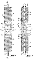
- FIG. 1 and 2 show a body 1 of a fuse according to the invention, which body essentially comprises three body regions 1a, 1b, and 1c and advantageously consists of plastic or ceramic.
- the body regions 1a and 1c can be identical to each other and connected to the middle body region 1b in a mirror image with respect to an axis of symmetry BB. you are advantageously with a connecting wire 2a, respectively. 2c, which can be used to solder the fuse according to the invention, for example into a printed circuit. It is advantageous if the two lateral body regions 1a and 1c have a substantially circular cross section and are shaped like screws. Where they merge into the middle body area 1b, the two outer body areas 1a and 1c each advantageously have a flattening 3a and 3c, the function of which is described below.
- the central body region 1b is advantageously essentially rectangular in plan view and has a border 4, within which a central block 5 with three transverse walls 5a, 5b and 5c is arranged.
- the middle transverse wall 5b is higher than the other two transverse walls 5a and 5c, to each of which an opening 6a or. 6c connects.
- the outer areas 5d and 5e of the central transverse wall 5b are advantageously pulled up to the height of the border 4 and serve the fuse wire 7 as lateral boundaries, respectively. Attacks.
- the fuse wire 7 which is advantageously a flat wire made of a eutectic lead-bismuth alloy with a melting point of about 125 ° C, from the flattening 3a on the side body area 1a through the Opening 6a in the central body region 1b via the three transverse walls 5a, 5b and 5c and through the opening 6c to flattening 3c on the lateral body region 1c.
- resistance wires 8a and 8c inserted in the helical grooves of the lateral body regions 1a and 1c, which in turn are also connected to the respective contact wires 2a, respectively. 2c are connected such that they are wrapped around them.
- the contact zones connecting wire 2a / resistance wire 8a, resistance wire 8a / fuse wire 7 as well as fuse wire 7 / resistance wire 8c and resistance wire 8c / connecting wire 2c can be covered with an electrically conductive adhesive, for example a copper or silver-containing two-component adhesive. Because of the low melting temperature of the fuse wire 7, soldering the fuse wire 7 to the resistance wires 8a and 8c is very difficult and hardly possible, but cannot be ruled out if the solder is selected accordingly.
- the three body regions 1a, 1b and 1c of the described embodiment variant of a fuse according to the invention are advantageously placed in a small plastic tube, preferably in the form of a shrink tube, in such a way that a component is produced which has both the appearance and also corresponds to a resistance in terms of dimensions.
- a fuse wire with a melting temperature of only approx. 125 ° C. is also very advantageous and can practically only be achieved thanks to the inventive connection of a fuse wire with resistance wire series resistors on a fuse body.
- the Resistor wire windings can be dispensed with and in their place, low-resistance connecting wires can establish the electrical connection between the fuse wire and the connecting wires.
- the fuse wire 7 is sufficiently thermally insulated from the connecting wires in such a way that they can easily be soldered into a printed circuit, for example, without the risk that the fuse wire will be melted as a result.
- the low melting point of the eutectic lead-bismuth alloy allows the fuse to also be used as a thermal fuse, which melts before overheating in the area of the circuit carrying the fuse can cause this damage.
- the shape of the central block 5 with its three transverse walls 5a, 5b and 5c offers great advantages over conventional fuses, because in no position of the fuse can blown and melted fuse wire form a fuse trace connecting the two remaining ends of the fuse wire.
- the embodiment variant of a fuse according to the invention described above and shown in the drawing can be produced automatically and inexpensively in large series.
- the level of the switching current can be determined by adequate dimensioning of the cross section of the fuse wire.
- the value of the two series resistors can also be easily adjusted by selecting an appropriate resistance wire.
- the connecting wires 2a and 2c can be replaced by contact shoes, for example, which can be placed in a known manner on the two ends of the lateral body regions 1a and 1c.
- the fuse according to the invention offers significant advantages over the known elements of this type, which lie in particular in the fact that a single, small-sized, discrete element can perform several functions.
Landscapes
- Fuses (AREA)
- Addition Polymer Or Copolymer, Post-Treatments, Or Chemical Modifications (AREA)
- Macromolecular Compounds Obtained By Forming Nitrogen-Containing Linkages In General (AREA)
- Techniques For Improving Reliability Of Storages (AREA)
- Emergency Protection Circuit Devices (AREA)
- Details Of Connecting Devices For Male And Female Coupling (AREA)
- Thermistors And Varistors (AREA)
Applications Claiming Priority (3)
| Application Number | Priority Date | Filing Date | Title |
|---|---|---|---|
| CH1003/89A CH677419A5 (OSRAM) | 1989-03-17 | 1989-03-17 | |
| CH1003/89 | 1989-03-17 | ||
| PCT/CH1990/000071 WO1990011608A1 (de) | 1989-03-17 | 1990-03-15 | Schmelzsicherung |
Publications (2)
| Publication Number | Publication Date |
|---|---|
| EP0417223A1 EP0417223A1 (de) | 1991-03-20 |
| EP0417223B1 true EP0417223B1 (de) | 1994-12-28 |
Family
ID=4200186
Family Applications (1)
| Application Number | Title | Priority Date | Filing Date |
|---|---|---|---|
| EP90903752A Expired - Lifetime EP0417223B1 (de) | 1989-03-17 | 1990-03-15 | Schmelzsicherung |
Country Status (16)
| Country | Link |
|---|---|
| EP (1) | EP0417223B1 (OSRAM) |
| JP (1) | JPH03504783A (OSRAM) |
| KR (1) | KR920700464A (OSRAM) |
| AT (1) | ATE116478T1 (OSRAM) |
| AU (1) | AU640917B2 (OSRAM) |
| BR (1) | BR9005961A (OSRAM) |
| CA (1) | CA2028862A1 (OSRAM) |
| CH (1) | CH677419A5 (OSRAM) |
| DE (1) | DE59008120D1 (OSRAM) |
| DK (1) | DK0417223T3 (OSRAM) |
| ES (1) | ES2070316T3 (OSRAM) |
| FI (1) | FI905680A0 (OSRAM) |
| HU (2) | HU208194B (OSRAM) |
| NO (1) | NO904973L (OSRAM) |
| RU (1) | RU2036527C1 (OSRAM) |
| WO (1) | WO1990011608A1 (OSRAM) |
Families Citing this family (6)
| Publication number | Priority date | Publication date | Assignee | Title |
|---|---|---|---|---|
| US5418516A (en) * | 1993-11-09 | 1995-05-23 | Littlefuse, Inc. | Surge resistor fuse |
| US6552646B1 (en) * | 2000-04-10 | 2003-04-22 | Bel-Fuse, Inc. | Capless fuse |
| CA2444182A1 (en) * | 2001-04-19 | 2002-10-31 | Pacific Engineering Corp. | Polyamide resin composition for fuse device |
| RU2367051C1 (ru) * | 2008-04-21 | 2009-09-10 | Федеральное агентство по образованию. Государственное образовательное учреждение высшего профессионального образования "Московский инженерно-физический институт (государственный университет)" | Высоковольтный резистор-предохранитель |
| RU2412501C1 (ru) * | 2009-12-16 | 2011-02-20 | Общество с ограниченной ответственностью "Холдинг Гефест" (ООО "Холдинг Гефест") | Предохранитель плавкий для систем пожарной автоматики |
| US10992254B2 (en) | 2014-09-09 | 2021-04-27 | Shoals Technologies Group, Llc | Lead assembly for connecting solar panel arrays to inverter |
Family Cites Families (7)
| Publication number | Priority date | Publication date | Assignee | Title |
|---|---|---|---|---|
| DE312052C (OSRAM) * | ||||
| GB191402301A (en) * | 1914-01-28 | 1914-11-12 | Herbert Henry Berry | Improvements in Electric Safety Fuses. |
| US1501018A (en) * | 1919-07-08 | 1924-07-08 | Gen Electric | Electric-circuit protective device |
| US2017492A (en) * | 1934-03-24 | 1935-10-15 | John B Glowacki | Cartridge ferrule type refillable fuse and element |
| US3793560A (en) * | 1973-06-18 | 1974-02-19 | J Schultheis | Resistive thermal protective device for inductances |
| GB2096844A (en) * | 1981-04-10 | 1982-10-20 | Beswick Kenneth E Ltd | Electrical fuse |
| GB2182811B (en) * | 1985-11-08 | 1990-09-19 | Cooper Ind Inc | Time lag electrical fuse |
-
1989
- 1989-03-17 CH CH1003/89A patent/CH677419A5/de not_active IP Right Cessation
-
1990
- 1990-03-15 JP JP2503870A patent/JPH03504783A/ja active Pending
- 1990-03-15 HU HU902187A patent/HU208194B/hu not_active IP Right Cessation
- 1990-03-15 HU HU902187A patent/HUT56660A/hu unknown
- 1990-03-15 EP EP90903752A patent/EP0417223B1/de not_active Expired - Lifetime
- 1990-03-15 BR BR909005961A patent/BR9005961A/pt unknown
- 1990-03-15 AT AT90903752T patent/ATE116478T1/de active
- 1990-03-15 AU AU51750/90A patent/AU640917B2/en not_active Ceased
- 1990-03-15 DE DE59008120T patent/DE59008120D1/de not_active Expired - Fee Related
- 1990-03-15 FI FI905680A patent/FI905680A0/fi not_active IP Right Cessation
- 1990-03-15 KR KR1019900702442A patent/KR920700464A/ko not_active Ceased
- 1990-03-15 DK DK90903752.5T patent/DK0417223T3/da not_active Application Discontinuation
- 1990-03-15 ES ES90903752T patent/ES2070316T3/es not_active Expired - Lifetime
- 1990-03-15 CA CA002028862A patent/CA2028862A1/en not_active Abandoned
- 1990-03-15 WO PCT/CH1990/000071 patent/WO1990011608A1/de not_active Ceased
- 1990-11-15 RU SU904831816A patent/RU2036527C1/ru active
- 1990-11-16 NO NO90904973A patent/NO904973L/no unknown
Also Published As
| Publication number | Publication date |
|---|---|
| ES2070316T3 (es) | 1995-06-01 |
| CH677419A5 (OSRAM) | 1991-05-15 |
| HU902187D0 (en) | 1991-08-28 |
| WO1990011608A1 (de) | 1990-10-04 |
| AU5175090A (en) | 1990-10-22 |
| EP0417223A1 (de) | 1991-03-20 |
| DK0417223T3 (da) | 1995-04-03 |
| BR9005961A (pt) | 1991-08-06 |
| KR920700464A (ko) | 1992-02-19 |
| CA2028862A1 (en) | 1990-09-18 |
| NO904973D0 (no) | 1990-11-16 |
| FI905680A7 (fi) | 1990-11-16 |
| ATE116478T1 (de) | 1995-01-15 |
| AU640917B2 (en) | 1993-09-09 |
| HUT56660A (en) | 1991-09-30 |
| RU2036527C1 (ru) | 1995-05-27 |
| JPH03504783A (ja) | 1991-10-17 |
| DE59008120D1 (de) | 1995-02-09 |
| NO904973L (no) | 1990-11-16 |
| FI905680A0 (fi) | 1990-11-16 |
| HU208194B (en) | 1993-08-30 |
Similar Documents
| Publication | Publication Date | Title |
|---|---|---|
| DE3785835T2 (de) | Chip-sicherung. | |
| DE3033323A1 (de) | Schutzvorrichtung fuer eine halbleitervorrichtung | |
| DE3146303C2 (de) | Anordnung zum Schutz einer spannungsbegrenzenden Schaltungsanordnung vor Überhitzung durch Überspannung | |
| DE102015102083B4 (de) | Komplexe Schutzvorrichtung | |
| DE60313510T2 (de) | Hochspannungs-dickfilmsicherung mit einem substrat mit hoher schaltleistung | |
| EP0516922A2 (de) | Thermische Überlast-Schutzeinrichtung für elektronische Bauelemente | |
| DE69702719T2 (de) | Elektrische sicherung | |
| EP0417223B1 (de) | Schmelzsicherung | |
| DE4403053C1 (de) | Luftfunkenstrecke zum Festlegen der Höchstspannung an einem Überspannungsableiter | |
| DE102008036672B3 (de) | Elektrische Schmelzsicherung | |
| DE3606690A1 (de) | Netzwerk-widerstandseinheit | |
| AT399069B (de) | Anordnung für den überspannungsschutz in niederspannungsanlagen | |
| DE3541151A1 (de) | Elektrische heizvorrichtung fuer schmiegsame waermegeraete | |
| DE2152047A1 (de) | Mit Sicherung versehenes Schaltungselement | |
| DE4112076A1 (de) | Chip-schmelzsicherung mit variabler zeit/strom-kennlinie | |
| DE19816907A1 (de) | Schutzstecker für eine Einrichtung der Telekommunikationstechnik | |
| DE69406623T2 (de) | Parallel- und Serienschutzmodul | |
| DE2935717C2 (de) | Überspannungsableiter | |
| DE19945012B4 (de) | Spannungsabhängiger Widerstand mit einer Überstromsicherung | |
| DE2137285A1 (de) | Selbsttaetige sicherheitsschaltung zur ueberwachung des leistungsschaltgliedes eines elektrischen stromverbrauchers | |
| DE112021006782B4 (de) | Überspannungsschutzschaltung und überspannungsschutzverfahren | |
| DE69227719T2 (de) | Widerstand, der imstande ist, als Überlastschalter zu agieren | |
| DE29909701U1 (de) | Schutzstecker für eine Einrichtung der Telekommunikationstechnik | |
| AT4508U1 (de) | Bauteil zum schutz gegen überspannungen | |
| EP0557753A2 (de) | Vorrichtung zum Schützen eines Geräts |
Legal Events
| Date | Code | Title | Description |
|---|---|---|---|
| PUAI | Public reference made under article 153(3) epc to a published international application that has entered the european phase |
Free format text: ORIGINAL CODE: 0009012 |
|
| 17P | Request for examination filed |
Effective date: 19901114 |
|
| AK | Designated contracting states |
Kind code of ref document: A1 Designated state(s): AT BE CH DE DK ES FR GB IT LI LU NL SE |
|
| 17Q | First examination report despatched |
Effective date: 19891123 |
|
| GRAA | (expected) grant |
Free format text: ORIGINAL CODE: 0009210 |
|
| REF | Corresponds to: |
Ref document number: 116478 Country of ref document: AT Date of ref document: 19950115 Kind code of ref document: T |
|
| ITF | It: translation for a ep patent filed | ||
| REF | Corresponds to: |
Ref document number: 59008120 Country of ref document: DE Date of ref document: 19950209 |
|
| ET | Fr: translation filed | ||
| PGFP | Annual fee paid to national office [announced via postgrant information from national office to epo] |
Ref country code: DK Payment date: 19950307 Year of fee payment: 6 |
|
| GBT | Gb: translation of ep patent filed (gb section 77(6)(a)/1977) |
Effective date: 19950208 |
|
| PGFP | Annual fee paid to national office [announced via postgrant information from national office to epo] |
Ref country code: GB Payment date: 19950310 Year of fee payment: 6 |
|
| PGFP | Annual fee paid to national office [announced via postgrant information from national office to epo] |
Ref country code: DE Payment date: 19950327 Year of fee payment: 6 |
|
| PG25 | Lapsed in a contracting state [announced via postgrant information from national office to epo] |
Ref country code: LU Free format text: LAPSE BECAUSE OF NON-PAYMENT OF DUE FEES Effective date: 19950331 |
|
| PGFP | Annual fee paid to national office [announced via postgrant information from national office to epo] |
Ref country code: NL Payment date: 19950331 Year of fee payment: 6 |
|
| REG | Reference to a national code |
Ref country code: DK Ref legal event code: T3 |
|
| PGFP | Annual fee paid to national office [announced via postgrant information from national office to epo] |
Ref country code: CH Payment date: 19950531 Year of fee payment: 6 |
|
| REG | Reference to a national code |
Ref country code: ES Ref legal event code: FG2A Ref document number: 2070316 Country of ref document: ES Kind code of ref document: T3 |
|
| PLBE | No opposition filed within time limit |
Free format text: ORIGINAL CODE: 0009261 |
|
| STAA | Information on the status of an ep patent application or granted ep patent |
Free format text: STATUS: NO OPPOSITION FILED WITHIN TIME LIMIT |
|
| 26N | No opposition filed | ||
| PGFP | Annual fee paid to national office [announced via postgrant information from national office to epo] |
Ref country code: BE Payment date: 19960209 Year of fee payment: 7 |
|
| PGFP | Annual fee paid to national office [announced via postgrant information from national office to epo] |
Ref country code: SE Payment date: 19960213 Year of fee payment: 7 |
|
| PGFP | Annual fee paid to national office [announced via postgrant information from national office to epo] |
Ref country code: FR Payment date: 19960228 Year of fee payment: 7 |
|
| PG25 | Lapsed in a contracting state [announced via postgrant information from national office to epo] |
Ref country code: GB Effective date: 19960315 Ref country code: DK Effective date: 19960315 |
|
| REG | Reference to a national code |
Ref country code: DK Ref legal event code: EBP |
|
| PGFP | Annual fee paid to national office [announced via postgrant information from national office to epo] |
Ref country code: ES Payment date: 19960320 Year of fee payment: 7 |
|
| PGFP | Annual fee paid to national office [announced via postgrant information from national office to epo] |
Ref country code: AT Payment date: 19960329 Year of fee payment: 7 |
|
| PG25 | Lapsed in a contracting state [announced via postgrant information from national office to epo] |
Ref country code: LI Effective date: 19960331 Ref country code: CH Effective date: 19960331 |
|
| PG25 | Lapsed in a contracting state [announced via postgrant information from national office to epo] |
Ref country code: NL Effective date: 19961001 |
|
| GBPC | Gb: european patent ceased through non-payment of renewal fee |
Effective date: 19960315 |
|
| REG | Reference to a national code |
Ref country code: CH Ref legal event code: PL |
|
| NLV4 | Nl: lapsed or anulled due to non-payment of the annual fee |
Effective date: 19961001 |
|
| PG25 | Lapsed in a contracting state [announced via postgrant information from national office to epo] |
Ref country code: DE Effective date: 19961203 |
|
| PG25 | Lapsed in a contracting state [announced via postgrant information from national office to epo] |
Ref country code: AT Effective date: 19970315 |
|
| PG25 | Lapsed in a contracting state [announced via postgrant information from national office to epo] |
Ref country code: SE Effective date: 19970316 |
|
| PG25 | Lapsed in a contracting state [announced via postgrant information from national office to epo] |
Ref country code: ES Free format text: LAPSE BECAUSE OF NON-PAYMENT OF DUE FEES Effective date: 19970317 |
|
| PG25 | Lapsed in a contracting state [announced via postgrant information from national office to epo] |
Ref country code: BE Effective date: 19970331 |
|
| BERE | Be: lapsed |
Owner name: SKYLINE HOLDING A.G. Effective date: 19970331 |
|
| PG25 | Lapsed in a contracting state [announced via postgrant information from national office to epo] |
Ref country code: FR Free format text: LAPSE BECAUSE OF NON-PAYMENT OF DUE FEES Effective date: 19971128 |
|
| EUG | Se: european patent has lapsed |
Ref document number: 90903752.5 |
|
| REG | Reference to a national code |
Ref country code: FR Ref legal event code: ST |
|
| REG | Reference to a national code |
Ref country code: ES Ref legal event code: FD2A Effective date: 19990301 |
|
| PG25 | Lapsed in a contracting state [announced via postgrant information from national office to epo] |
Ref country code: IT Free format text: LAPSE BECAUSE OF NON-PAYMENT OF DUE FEES Effective date: 20050315 |