EP0416717B1 - Roll stand for a planetary rolling mill - Google Patents
Roll stand for a planetary rolling mill Download PDFInfo
- Publication number
- EP0416717B1 EP0416717B1 EP90250213A EP90250213A EP0416717B1 EP 0416717 B1 EP0416717 B1 EP 0416717B1 EP 90250213 A EP90250213 A EP 90250213A EP 90250213 A EP90250213 A EP 90250213A EP 0416717 B1 EP0416717 B1 EP 0416717B1
- Authority
- EP
- European Patent Office
- Prior art keywords
- rolling
- roll stand
- chocks
- supporting member
- segments
- Prior art date
- Legal status (The legal status is an assumption and is not a legal conclusion. Google has not performed a legal analysis and makes no representation as to the accuracy of the status listed.)
- Expired - Lifetime
Links
- 238000005096 rolling process Methods 0.000 title claims description 81
- 230000002787 reinforcement Effects 0.000 claims description 3
- 238000009434 installation Methods 0.000 description 5
- 230000000712 assembly Effects 0.000 description 2
- 238000000429 assembly Methods 0.000 description 2
- 229910000760 Hardened steel Inorganic materials 0.000 description 1
- 238000006243 chemical reaction Methods 0.000 description 1
- 238000010438 heat treatment Methods 0.000 description 1
- 238000004519 manufacturing process Methods 0.000 description 1
- 239000000463 material Substances 0.000 description 1
- 238000000034 method Methods 0.000 description 1
- 230000001105 regulatory effect Effects 0.000 description 1
- 238000011179 visual inspection Methods 0.000 description 1
Images


Classifications
-
- B—PERFORMING OPERATIONS; TRANSPORTING
- B21—MECHANICAL METAL-WORKING WITHOUT ESSENTIALLY REMOVING MATERIAL; PUNCHING METAL
- B21B—ROLLING OF METAL
- B21B13/00—Metal-rolling stands, i.e. an assembly composed of a stand frame, rolls, and accessories
- B21B13/18—Metal-rolling stands, i.e. an assembly composed of a stand frame, rolls, and accessories for step-by-step or planetary rolling; pendulum mills
- B21B13/20—Metal-rolling stands, i.e. an assembly composed of a stand frame, rolls, and accessories for step-by-step or planetary rolling; pendulum mills for planetary rolling
Definitions
- the invention relates to a roll stand for a planetary rolling mill with stand, stationary support bodies with rolling segments, which are mounted in chocks, and are mounted in cages around the intermediate and work rolls rotating around the support bodies; see e.g. DE-C 1 140 534.
- the Platzer planetary rolling mill named after its developer, the work rolls are brought against the centrifugal force against the intermediate rolls and these against the supporting bodies by disc spring assemblies when circulating around the stationary supporting bodies.
- the surface of the support body constitutes an exact cylinder surface. In this area of the forming zone, the rolling surface deviates from the exact circular arc shape in order to ensure a perfect, i.e. to ensure groove-free rolling surface.
- This roller geometry which deviates from the exact cylinder surface, is realized for wear reasons by means of rolling segments inserted into the support body.
- These rolling segments which form the rolling path for the intermediate rolls, are made of hardened steel and are interchangeably fastened in recesses in the supporting body.
- the rolling segments are subjected to very high mechanical loads, because in the forming zone the radial rolling forces in the stationary support body are applied via them be directed. High Hertzian pressures occur during the forming process when the support rollers roll on the roll segment. With a number of 24 support rollers per cage, each rolling segment is rolled over 24 times with each rotation of the cage.
- the invention has for its object to significantly increase the time intervals between changing the rolling segments and to reduce the work involved.
- the rolling segments currently in use are so worn out after approximately 25 hours of operation, even with optimal heat treatment, that they have to be replaced.
- the support body is now equipped with 4 rolling segments evenly distributed over the circumference, the support bodies are simply extended out of the roll stand, rotated through 90 ° and reinstalled. In this way, the next of the four rolling segments comes into the working position.
- rotating the support body coincides with every fourth regrinding of the work rolls. This means that no separate removal and installation is necessary for rotating the support bodies, since they are only rotated through 90 ° and reinstalled every fourth grinding of the work rolls, if they have to be removed anyway.
- Two rolling rings are suitable for this, one on each side of the support body.
- the intermediate rolls are also guided on a perfect circular path in the region of the three rolling segments which are not in engagement, so that a jerky placement of the intermediate rolls is avoided.
- the rolling rings In the work area, the rolling rings have recesses so that the rollers can rest on the flattening of the rolling segments.
- the chocks have a square basic shape, with the help of which the exact positioning of the rolling segments, each offset by 90 °, is achieved.
- the advantage of the rolling stand according to the invention is that the active rolling segments only after one Operating time of approx. 100 hours must be replaced, and that when the work rolls are replaced or regrind at this point anyway, the next pair of rolling segments is brought into the working position by installing the support body rotated through 90 °.
- the removal and installation of the rolling segments is no longer necessary, as is the removal and reinstallation of 5 work rolls and 5 intermediate rolls. It is also achieved that the 4 pairs of worn rolling segments are replaced when the work rolls have to be replaced, so that no additional work and assembly work is required.
- An alternative embodiment of the invention is that the chocks are octagonal and each support body has eight rolling segments. This has the advantage that the time span between the necessary replacement of the rolling segments can be doubled again.
- An advantageous development of the invention consists in that the two rolling rings of a support body can be rotated relative to the support body by a rotating device and can be braced against the support body by clamping devices. This makes it possible to turn the rolling rings relative to the support body by 90 ° or 45 ° in a simple and quick manner. This rotation is necessary so that the cut-outs of the rolling rings match the processing zone again. With these devices, the rolling rings are rotated without disassembly and assembly work and under the pressure of the disc spring packets. In order to turn the rolling rings, are arranged between the rolling segments (preferably the four) solved, with the help of which the rings are clamped against the support body during operation.
- each support body is expediently rotated synchronously by the required 90 ° or 45 °.
- the rolling rings on the side facing the support body are provided with an internal toothing.
- Drive pinions engage in this internal toothing and are mounted on a common shaft that runs in a bore in the support body and is rotatably mounted therein.
- the drive takes place by means of a drive unit with a stepper motor arranged in one of the chocks, so that an exact positioning in the installed state can be carried out without measuring and regulating device and without visual inspection.
- a hydraulic reinforcement and a self-locking gear are arranged between it and the pinion.
- This self-locking gear (eg a worm gear) has the advantage that it reliably prevents shaking in the operating state, ie a gradual overcoming of the clamping force of the clamping device.
- the clamping devices are advantageously designed as clamping cylinders which are arranged in bores in the support body.
- the clamping force is generated by disc springs, the loosening for turning the rolling rings is done by pressurizing the cylinder space.
- the free end of the piston rod has a head or a slot nut which engages in an annular groove of the rolling segment, which is incorporated on the surface facing the support body. When the cylinder is relieved, the spring force of the disc spring pulls the Roll-off ring firmly against the support body.
- the edge lengths or the distance between the side surfaces of the latter are smaller than the outer diameter of the planetary gear set.
- Two strips are provided for each chock, which are screwed onto the vertical side surfaces of the chocks according to the installation position and are mounted accordingly when the support body is turned by 90 ° or 45 °. This is the only manual action when rotating the support body.
- the support bodies In order to facilitate the respective rotation of the support bodies, they can be equipped with pivot pins at each end, which protrude beyond the chocks. This means that the support body can be rotated by 90 ° or after the planetary roller has moved out of the stand. 45 ° in a rotating device standing next to the roll stand.
- Fig. 1 the upper part of a planetary mill is shown in cross section.
- the chock 1, in which the support body 2 is held in the stand 4, is guided in the stand 4 by means of strips 3. These strips 3 are unscrewed when the chocks 1 are rotated (in the example by 90 °) and screwed back into the new mounting position on the vertical side faces of the chocks 1.
- the four rolling segments 5 are screwed into the support body 2 offset by 90 °. Due to the geometry of the rolling segments 5 which differs from an exact cylindrical shape, the work rolls 6, which are supported on the intermediate rolls 7, are guided in the roll gap in such a way that the rolling material 8 receives a perfect surface.
- the work rolls 6 are drawn in the direction of the support body axis 9 as they rotate around the support body 2 by disc spring assemblies (not shown).
- the four clamping devices 10 arranged in the support body 2 lie between the rolling segments 5.
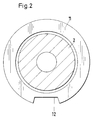
- each support body 2 is provided with a rolling ring 11 at both ends, as shown in FIG. 2.
- These rolling rings 11, on which the intermediate rolls 7 roll, can be rotated on the supporting body 2, but are arranged in a locked manner during the rolling, and apart from a recess 12 in the area of the roll gap circular profile.
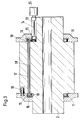
- Fig. 3 the two devices are shown, by means of which the two rolling rings 11 can be locked or rotated on the support body 2. Only one of the eight clamping devices 10, which are arranged in each support body 2, is shown here. To rotate the rolling rings 11 mounted on the support body 2, the clamping devices 10 (details are explained with reference to FIG. 4) are released. The drive takes place via the drive unit 35 (details are explained with reference to FIG. 6) and a shaft 14 mounted in a recess 13 of the support body 2. The pinion 15 fastened on the shaft 14 is in engagement with one of the two drive pinions 16, which are on a shaft 18 extending in a bore 17 of the support body 2 are fastened. These drive pinions 16 are in engagement with the internal toothing 19 of the rolling rings 11.
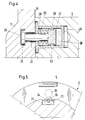
- the rolling ring 11 has an annular groove 20 into which the head or the sliding block 21 of the tie rod 22 engages.
- the tie rod 22 also represents the piston rod of the clamping cylinder 23, which is arranged in a bore 24 of the support body 2.
- the plate spring 25 which is supported on the one hand on the inner wall 26 of the clamping cylinder 23 and on the other hand on the piston 27 provided with a seal 28, the rolling ring 11 with the inner surface 29 is pulled firmly against the support body 2.
- the cylinder spaces 30 are subjected to such a high pressure that the tensioning force of the plate springs 25 is overcome.
- Fig. 5 shows the arrangement of the shaft 14 in the Recess 13 of the support body 2.
- the pillow block bearing is designated 31.
- the pinion 15, a drive pinion 16 and a rolling segment 5 can also be seen.
- the drive unit 12 (FIG. 6) consists of a stepper motor 32 which is flanged to a hydraulic amplifier 33 (for example an electrohydraulic rotary amplifier, type SVIR from Hartmann & Lämmle).
- the output side of the hydraulic reinforcement 33 is connected to a self-locking gear 34 (for example a worm gear).
Landscapes
- Engineering & Computer Science (AREA)
- Mechanical Engineering (AREA)
- Metal Rolling (AREA)
- Reduction Rolling/Reduction Stand/Operation Of Reduction Machine (AREA)
- Rolling Contact Bearings (AREA)
Description
Die Erfindung bezieht sich auf ein Walzgerüst für ein Planetenwalzwerk mit Ständer, in Einbaustücken gelagerten, stationären Stützkörpern mit Abrollsegmenten und in Käfigen gelagerten, um die Stützkörper umlaufenden Zwischen- und Arbeitswalzen; siehe z.B. DE-C 1 140 534. Bei einem solchen Planetenwalzwerk, dem nach seinem Entwickler benannten Platzer-Planetenwalzwerk, werden die Arbeitswalzen durch Tellerfederpakete beim Umlauf um die stationären Stützkörper entgegen der Fliehkraft gegen die Zwischenwalzen und diese gegen die Stützkörper zur Anlage gebracht. Die Oberfläche der Stützkörper stellt bis auf einen kleinen Bereich der Umformzone eine exakte Zylinderfläche dar. In diesem Bereich der Umformzone weicht die Abrollfläche von der exakten Kreisbogenform ab, um eine einwandfreie, d.h. rillenfreie Walzgutoberfläche zu gewährleisten. Diese von der exakten Zylinderfläche abweichende Walzengeometrie wird aus Verschleißgründen mittels in die Stützkörper eingesetzter Abrollsegmente realisiert. Diese, die Abrollbahn für die Zwischenwalzen bildenden Abrollsegmente sind aus gehärtetem Stahl und austauschbar in Ausnehmungen des Stützkörpers befestigt.The invention relates to a roll stand for a planetary rolling mill with stand, stationary support bodies with rolling segments, which are mounted in chocks, and are mounted in cages around the intermediate and work rolls rotating around the support bodies; see e.g. DE-C 1 140 534. In such a planetary rolling mill, the Platzer planetary rolling mill named after its developer, the work rolls are brought against the centrifugal force against the intermediate rolls and these against the supporting bodies by disc spring assemblies when circulating around the stationary supporting bodies. Except for a small area of the forming zone, the surface of the support body constitutes an exact cylinder surface. In this area of the forming zone, the rolling surface deviates from the exact circular arc shape in order to ensure a perfect, i.e. to ensure groove-free rolling surface. This roller geometry, which deviates from the exact cylinder surface, is realized for wear reasons by means of rolling segments inserted into the support body. These rolling segments, which form the rolling path for the intermediate rolls, are made of hardened steel and are interchangeably fastened in recesses in the supporting body.
Die Abrollsegmente sind mechanisch sehr hoch belastet, weil in der Umformzone über sie die radialen Walzkräfte in den stationären Stützkörper geleitet werden. Es entstehen während der Umformung beim Abrollen der Stützwalzen auf dem Abrollsegment hohe Hertz'sche Pressungen. Bei einer Zahl von 24 Stützwalzen pro Käfig wird jedes Abrollsegement bei jeder Käfigumdrehung 24 mal überrollt.The rolling segments are subjected to very high mechanical loads, because in the forming zone the radial rolling forces in the stationary support body are applied via them be directed. High Hertzian pressures occur during the forming process when the support rollers roll on the roll segment. With a number of 24 support rollers per cage, each rolling segment is rolled over 24 times with each rotation of the cage.
Bei einer üblichen Käfigdrehzahl von 120 Umdrehungen pro Min. und einer Last von ca. 85 t ergibt sich eine Standzeit eines Segmentes von ca. 25 Stunden. Eine beginnende Grübchenbildung zeigt an, daß das Nachschleifen des Segmentes notwendig wird. Zum Nachschleifen muß der Walzensatz aus dem Ständer ausgefahren werden, damit man das Abrollsegment demontieren kann. Man muß fünf Arbeitswalzen und fünf Stützwalzen aus jedem Satz ausbauen, bevor man die Abrollsegmente demontieren kann. Diese sind beispielsweise mit Schrauben im Stützkörper befestigt. Das alte Abrollsegment wird ausgebaut und auf einer Flächenschleifmaschine nachgearbeitet. Ein anderes, fertig geschliffenes Abrollsegment wird in den Walzensatz eingebaut und dieser mit den fünf Stütz- und Arbeitswalzen wieder komplettiert. Es bedeutet einen hohen Arbeits- und Zeitaufwand, d.h. eine große Einschränkung der Verfügbarkeit des Planetenwalzwerkes, wenn jeweils nach 25 Stunden die Abrollsegemente ausgebaut und nachgeschliffen werden müssen.With a normal cage speed of 120 revolutions per minute and a load of approx. 85 t, the service life of a segment is approx. 25 hours. An incipient dimple indicates that the segment must be reground. For regrinding, the roller set must be extended from the stand so that the rolling segment can be dismantled. You have to remove five work rolls and five backup rolls from each set before you can dismantle the unwinding segments. These are fastened, for example, with screws in the support body. The old rolling segment is removed and reworked on a surface grinding machine. Another, fully ground roll segment is installed in the roller set and this is completed again with the five support and work rollers. It means a lot of work and time, i.e. a major restriction of the availability of the planetary rolling mill if the rolling segments have to be removed and reground every 25 hours.
Hinzu kommt, daß es bei kleineren Walzgerüsten zwar noch möglich ist, die Arbeitswalzen von Hand aus- und einzubauen, daß für die Handhabung der Abrollsegmente jedoch bereits ein leichter Kran benötigt wird. Bei mittleren und größeren Walzgerüsten jedoch, bei denen die Arbeitswalzen bis zu 600 kg wiegen, kommt man ohne entsprechende Hebezeuge nicht aus, was zu erhöhten Investitionskosten und einer Verlängerung der Aus- und Einbauzeiten führt.In addition, it is still possible with smaller roll stands to remove and install the work rolls by hand, but that a light crane is already required to handle the unwinding segments. With medium and large roll stands, however, where the work rolls weigh up to 600 kg, you cannot do without the appropriate lifting equipment, which leads to increased investment costs and an extension of the and installation times.
Bei einer Produktionsmaschine bzw. -Anlage sind lange Stillstandszeiten nicht akzeptabel. Dies gilt ganz besonders für Anlagen mit hohem Investitionsvolumen. Ziel für ein Walzgerüst muß es daher sein, sowohl die Zwischenräume zwischen dem notwendigen Austausch der Arbeitswalzen und der Abrollsegmente zu verlängern als auch die Zeit für den Austausch bzw. Umbau zu verringern.Long downtimes are not acceptable for a production machine or system. This applies particularly to systems with a high investment volume. The aim of a roll stand must therefore be to both extend the gaps between the necessary replacement of the work rolls and the unwinding segments and to reduce the time for the replacement or conversion.
Da es durch das Schleifen der Arbeitswalzen in eingebautem Zustand gelungen ist, den diesbezüglichen Arbeitsaufwand wesentlich zu reduzieren und die Zeit zwischen einem Wechsel der Arbeitswalzen auf ca. 100 Stunden Einsatzzeit zu erhöhen, werden die Abrollsegmente mit einer Standzeit von ca. 25 Stunden zum zeit- und kostenbestimmenden Faktor.Since grinding of the work rolls in the installed state has succeeded in significantly reducing the work involved and increasing the time between changing the work rolls to around 100 hours of use, the rolling segments with a service life of approx. 25 hours are currently and cost-determining factor.
Der Erfindung liegt die Aufgabe zugrunde, die Zeitabstände zwischen dem Wechseln der Abrollsegmente wesentlich zu vergrößern und den damit verbundenen Arbeitsaufwand zu verringern.The invention has for its object to significantly increase the time intervals between changing the rolling segments and to reduce the work involved.
Diese Aufgabe wird bei einem Walzgerüst der eingangs beschriebenen Art durch die Kennzeichnenden Merkmale der Patentansprüche 1 und 2 gelöst. Durch ein solchermaßen gestaltetes Walzgerüst werden die üblicherweise ca. alle 25 Stunden notwendigen und sehr zeitaufwendigen Schritte zum Ausbau der abgenützten Abrollsegmente und Einbau von nachgeschliffenen Abrollsegmenten überflüssig.This object is achieved in a roll stand of the type described in the introduction by the characterizing features of
Diese Schritte sind: Ausfahren der beiden Stützkörper aus dem Walzgerüst, Ausbau von jeweils 5 Arbeitswalzen und 5 Zwischenwalzen, Auswechseln der Abrollsegmente und Wiedereinbau in umgekehrter Reihenfolge.These steps are: Extending the two support bodies from the roll stand, removing 5 work rolls and 5 intermediate rolls each, changing the rolling segments and reinstalling them in reverse order.
Bei einem Walzgerüst entsprechend der Erfindung sind die gerade im Einsatz befindlichen Abrollsegmente auch bei optimaler Wärmebehandlung nach ca. 25 Stunden Betriebszeit so weit abgenützt, daß sie ersetzt werden müssen. Da der Stützkörper nun aber mit je 4 gleichmäßig am Umfang verteilten Abrollsegmenten ausgerüstet ist, werden die Stützkörper lediglich aus dem Walzgerüst ausgefahren, um 90° gedreht und wieder eingebaut. Auf diese Weise kommt das nächste der vier Abrollsegmente in Arbeitsposition. Da die Standzeit der Arbeitswalzen bis zum notwendigen Nachschleifen ca. 6 Stunden beträgt, fällt ein Drehen der Stützkörper mit jedem vierten Nachschleifen der Arbeitswalzen zusammen. Das bedeutet, daß für das Drehen der Stützkörper kein eigener Aus- und Einbau notwendig ist, da sie lediglich bei jedem vierten Schleifen der Arbeitswalzen, wenn sie ohnehin ausgebaut werden müssen, um 90° gedreht und wieder eingebaut werden.In a rolling stand according to the invention, the rolling segments currently in use are so worn out after approximately 25 hours of operation, even with optimal heat treatment, that they have to be replaced. However, since the support body is now equipped with 4 rolling segments evenly distributed over the circumference, the support bodies are simply extended out of the roll stand, rotated through 90 ° and reinstalled. In this way, the next of the four rolling segments comes into the working position. As the service life of the work rolls until the necessary regrinding is approx. 6 hours, rotating the support body coincides with every fourth regrinding of the work rolls. This means that no separate removal and installation is necessary for rotating the support bodies, since they are only rotated through 90 ° and reinstalled every fourth grinding of the work rolls, if they have to be removed anyway.
Durch die Anordnung von 4 Abrollsegmenten je Stützkörper, die nacheinander zum Einsatz gebracht werden, ergibt sich ein weiterer Vorteil. Es entfällt auch das sonst üblicherweise zum Wechseln der Abrollsegmente notwendige Aus- und Einbauen von jeweils 5 Arbeitswalzen und 5 Zwischenwalzen, da dieser Arbeitsgang genau dann erledigt werden kann, wenn die Arbeitswalzen nach 16maligem Nachschleifen endgültig verbraucht sind, d.h. den kleinsten zulässigen Durchmesser erreicht haben und durch neue ersetzt werden müssen.The arrangement of 4 rolling segments per support body, which are used one after the other, results in a further advantage. There is also no need to remove and install 5 work rolls and 5 intermediate rolls, which is usually necessary to change the unwinding segments, since this operation can be carried out precisely when the work rolls are finally used up after 16 regrindings, i.e. have reached the smallest permitted diameter and must be replaced by new ones.
Bei bisher gebauten Platzer-Walzgerüsten werden die Arbeitswalzen mittels Tellerfeder-Paketen beim Umlauf um die Stützkörper entgegen der Fliehkraft gegen die Zwischenwalzen gedrückt und diese in ständigem Kontakt mit der zylindrischen Oberfläche der Stützkörper gehalten. Im Bereich des Abrollsegmentes mit seiner von einer exakten Zylinderfläche abweichenden Geometrie werden die Walzen durch die Walzkraft angedrückt. Bei dem erfindungsgemäßen Walzgerüst würde es bei den üblichen Drehzahlen im Bereich der drei zusätzlichen Abrollsegmente aufgrund der Geometrie zum kurzzeitigen Abheben und anschließenden stoßartigen Wiederaufsetzen der Zwischenwalzen auf der Stützkörperoberfläche kommen und damit zu Verschleiß führen. Bei der Erfindung ist daher durch eine konstruktive Maßnahme Vorsorge getroffen, daß das Abheben der Walzen beim Überrollen der drei nicht im Eingriff befindlichen Abrollsegmente sicher vermieden wird. Hierfür eignen sich zwei Abrollringe und zwar einer auf jeder Seite des Stützkörpers. Durch diese Abrollringe werden die Zwischenwalzen auch im Bereich der drei nicht im Eingriff befindlichen Abrollsegmente auf einer einwandfreien Kreisbahn geführt, so daß ein stoßartiges Aufsetzen der Zwischenwalzen vermieden wird. Im Arbeitsbereich weisen die Abrollringe Ausnehmungen auf, so daß sich hier die Walzen an die Abplattungen der Abrollsegmente anlegen können.In previously built Platzer mill stands, the work rolls are pressed against the intermediate rolls against the centrifugal force by means of plate spring packets while rotating around the support bodies, and these are kept in constant contact with the cylindrical surface of the support bodies. In the area of the rolling segment with its geometry deviating from an exact cylinder surface, the rollers are pressed on by the rolling force. In the roll stand according to the invention, at the usual speeds in the region of the three additional rolling segments, due to the geometry, the intermediate rolls would briefly lift off and then be put back on the support body surface in an abrupt manner and thus lead to wear. In the invention, provision is therefore made by a constructive measure that the lifting of the rollers when rolling over the three non-engaged rolling segments is reliably avoided. Two rolling rings are suitable for this, one on each side of the support body. By means of these rolling rings, the intermediate rolls are also guided on a perfect circular path in the region of the three rolling segments which are not in engagement, so that a jerky placement of the intermediate rolls is avoided. In the work area, the rolling rings have recesses so that the rollers can rest on the flattening of the rolling segments.
Die Einbaustücke haben eine quadratische Grundform, mit deren Hilfe die exakte Positionierung der jeweils um 90° versetzt angeordneten Abrollsegmente erreicht wird.The chocks have a square basic shape, with the help of which the exact positioning of the rolling segments, each offset by 90 °, is achieved.
Der Vorteil des erfindungsgemäßen Walzgerüstes besteht darin, daß die aktiven Abrollsegmente erst nach einer Einsatzzeit von ca. 100 Stunden ausgewechselt werden müssen, und daß bei dem zu diesem Zeitpunkt ohnehin notwendigen Auswechseln bzw. Nachschleifen der Arbeitswalzen durch einen um 90° gedrehten Einbau der Stützkörper das nächste Paar Abrollsegmente in die Arbeitsstellung gebracht wird. Das Aus- und Einbauen der Abrollsegmente entfällt zu diesem Zeitpunkt ebenso wie der dazu notwendige Aus- und Wiedereinbau von jeweils 5 Arbeitswalzen und 5 Zwischenwalzen. Es wird darüberhinaus erreicht, daß das Auswechseln der 4 Paar abgenutzten Abrollsegmente dann erfolgt, wenn die Arbeitswalzen erneuert werden müssen, so daß hierfür kein zusätzlicher Arbeits- und Montageaufwand entsteht.The advantage of the rolling stand according to the invention is that the active rolling segments only after one Operating time of approx. 100 hours must be replaced, and that when the work rolls are replaced or regrind at this point anyway, the next pair of rolling segments is brought into the working position by installing the support body rotated through 90 °. The removal and installation of the rolling segments is no longer necessary, as is the removal and reinstallation of 5 work rolls and 5 intermediate rolls. It is also achieved that the 4 pairs of worn rolling segments are replaced when the work rolls have to be replaced, so that no additional work and assembly work is required.
Eine alternative Ausführungsform der Erfindung besteht darin, daß die Einbaustücke achteckig ausgeführt sind und jeder Stützkörper acht Abrollsegmente aufweist. Das hat den Vorteil, daß die Zeitspanne zwischen dem notwendigen Auswechseln der Abrollsegmente noch einmal verdoppelt werden kann.An alternative embodiment of the invention is that the chocks are octagonal and each support body has eight rolling segments. This has the advantage that the time span between the necessary replacement of the rolling segments can be doubled again.
Eine vorteilhafte Weiterbildung der Erfindung besteht darin, daß die beiden Abrollringe eines Stützkörpers durch eine Dreheinrichtung gegenüber dem Stützkörper drehbar und durch Klemmeinrichtungen gegen den Stützkörper verspannbar sind. Es ist dadurch möglich, auf einfache und schnelle Art das Drehen der Abrollringe gegenüber dem Stützkörper um 90° bzw. 45° vorzunehmen. Diese Drehung ist nötig, damit die Aussparungen der Abrollringe wieder mit der Bearbeitungszone übereinstimmt. Es werden mit diesen Einrichtungen die Abrollringe ohne Demontage- und Montagearbeiten und unter dem Anpreßdruck der Tellerfeder-Pakete gedreht. Zum Drehen der Abrollringe werden zwischen den Abrollsegmenten angeordnete (vorzugsweise deren vier) gelöst, mit deren Hilfe die Ringe während des Betriebes gegen die Stützkörper festgeklemmt werden.An advantageous development of the invention consists in that the two rolling rings of a support body can be rotated relative to the support body by a rotating device and can be braced against the support body by clamping devices. This makes it possible to turn the rolling rings relative to the support body by 90 ° or 45 ° in a simple and quick manner. This rotation is necessary so that the cut-outs of the rolling rings match the processing zone again. With these devices, the rolling rings are rotated without disassembly and assembly work and under the pressure of the disc spring packets. In order to turn the rolling rings, are arranged between the rolling segments (preferably the four) solved, with the help of which the rings are clamped against the support body during operation.
Die beiden Abrollringe eines jeden Stützkörpers werden zweckmäßig synchron um die erforderlichen 90° bzw. 45°gedreht. Dazu ist vorgesehen, die Abrollringe auf der dem Stützkörper zugekehrten Seite mit einer Innenverzahnung zu versehen. In diese Innenverzahnung greifen Antriebsritzel ein, die auf einer gemeinsamen, in einer Bohrung des Stützkörpers verlaufenden und darin drehbar gelagerten Welle befestigt sind. Der Antrieb erfolgt durch eine in einem der Einbaustücke angeordnete Antriebseinheit mit Schrittmotor, so daß eine genaue Positionierung im eingebauten Zustand ohne Meß- und Regeleinrichtung und ohne Sichtkontrolle vorgenommen werden kann. Um die Abmessung des Schrittmotors klein halten zu können, ist zwischen diesem und dem Ritzel eine hydraulische Verstärkung sowie ein selbsthemmendes Getriebe angeordnet. Dieses selbsthemmende Getriebe (z.B. ein Schneckenradgetriebe) hat den Vorteil, daß damit ein Losrütteln im Betriebszustand, d.h. ein allmähliches Überwinden der Klemmkraft der Klemmeinrichtung, sicher vermieden wird.
Die Klemmeinrichtungen werden vorteilhaft als Klemmzylinder ausgebildet, die in Bohrungen des Stützkörpers angeordnet sind. Die Klemmkraft wird durch Tellerfedern erzeugt, das Lösen zum Drehen der Abrollringe erfolgt durch Druckbeaufschlagung des Zylinderraumes. Die Kolbenstange weist an ihrem freien Ende einen Kopf bzw. einen Nutstein auf, der in eine Ringnut des Abrollsegmentes eingreift, die auf der dem Stützkörper zugekehrten Fläche eingearbeitet ist. Beim Entlasten des Zylinders zieht die Federkraft der Tellerfeder den Abrollring fest gegen den Stützkörper.The two rolling rings of each support body are expediently rotated synchronously by the required 90 ° or 45 °. For this purpose, it is provided that the rolling rings on the side facing the support body are provided with an internal toothing. Drive pinions engage in this internal toothing and are mounted on a common shaft that runs in a bore in the support body and is rotatably mounted therein. The drive takes place by means of a drive unit with a stepper motor arranged in one of the chocks, so that an exact positioning in the installed state can be carried out without measuring and regulating device and without visual inspection. In order to keep the size of the stepper motor small, a hydraulic reinforcement and a self-locking gear are arranged between it and the pinion. This self-locking gear (eg a worm gear) has the advantage that it reliably prevents shaking in the operating state, ie a gradual overcoming of the clamping force of the clamping device.
The clamping devices are advantageously designed as clamping cylinders which are arranged in bores in the support body. The clamping force is generated by disc springs, the loosening for turning the rolling rings is done by pressurizing the cylinder space. The free end of the piston rod has a head or a slot nut which engages in an annular groove of the rolling segment, which is incorporated on the surface facing the support body. When the cylinder is relieved, the spring force of the disc spring pulls the Roll-off ring firmly against the support body.
Um den Ein- und Ausbau der Stützkörper mit ihren Einbaustücken möglichst einfach zu gestalten, sind die Kantenlängen bzw. der Abstand der Seitenflächen der letzteren kleiner als der Außendurchmesser des Planetensatzes. Es sind je Einbaustücke zwei Leisten vorgesehen, die entsprechend der Einbaulage an den senkrechten Seitenflächen der Einbaustücke angeschraubt sind und beim Drehen des Stützkörpers um 90° bzw. 45° entsprechend montiert werden. Dies ist die einzige, manuelle Aktion beim Drehen der Stützkörper.In order to make the installation and removal of the support bodies with their chocks as simple as possible, the edge lengths or the distance between the side surfaces of the latter are smaller than the outer diameter of the planetary gear set. Two strips are provided for each chock, which are screwed onto the vertical side surfaces of the chocks according to the installation position and are mounted accordingly when the support body is turned by 90 ° or 45 °. This is the only manual action when rotating the support body.
Um das jeweilige Drehen der Stützkörper zu erleichtern, können diese an jedem Ende mit Drehzapfen ausgestattet sein, die über die Einbaustücke nach außen hinausragen. Damit ist ein Drehen der Stützkörper nach dem Ausfahren derPlanetenwalze aus dem Gerüst um 90°bzw. 45° in einer neben dem Walzgerüst stehenden Drehvorrichtung auf einfache Weise möglich.In order to facilitate the respective rotation of the support bodies, they can be equipped with pivot pins at each end, which protrude beyond the chocks. This means that the support body can be rotated by 90 ° or after the planetary roller has moved out of the stand. 45 ° in a rotating device standing next to the roll stand.
Die Erfindung ist anhand eines Beispiels in den Fig. 1 bis 6 dargestellt und im folgenden näher beschrieben, wobei auf Details, wie sie dem Fachmann jederzeit geläufig sind, verzichtet wurde. Es zeigen:
- Fig. 1
- einen Querschnitt durch den oberen Stützkörper
- Fig. 2
- einen Abrollring
- Fig. 3
- einen Längsschnitt durch einen Stützkörper mit Abrollringen, Dreh- und Klemmeinrichtung
- Fig. 4
- einen Klemmzylinder mit Tellerfeder
- Fig. 5
- die Anordnung der Antriebswelle
- Fig. 6
- eine Antriebseinheit
- Fig. 1
- a cross section through the upper support body
- Fig. 2
- a rolling ring
- Fig. 3
- a longitudinal section through a support body with rolling rings, rotating and clamping device
- Fig. 4
- a clamping cylinder with a plate spring
- Fig. 5
- the arrangement of the drive shaft
- Fig. 6
- a drive unit
In Fig. 1 ist der obere Teil eines Planetenwalzgerüstes im Querschnitt dargestellt. Das Einbaustück 1, in dem der Stützkörper 2 im Ständer 4 gehalten ist, wird mittels Leisten 3 im Ständer 4 geführt. Diese Leisten 3 werden beim Drehen der Einbaustücke 1 (im Beispiel um 90°) abgeschraubt und der neuen Einbaulage entsprechend an den senkrechten Seitenflächen der Einbaustücke 1 wieder angeschraubt. Die vier Abrollsegmente 5 sind um jeweils 90° versetzt in dem Stützkörper 2 verschraubt. Durch die von einer exakten Zylinderform abweichende Geometrie der Abrollsegmente 5 werden die Arbeitswalzen 6, die sich auf den Zwischenwalzen 7 abstützen, im Walzspalt so geführt, daß das Walzmaterial 8 eine einwandfreie Oberfläche erhält. Die Arbeitswalzen 6 werden beim Umlaufen um den Stützkörper 2 von nicht dargestellten Tellerfeder-Paketen in Richtung der Stützkörperachse 9 gezogen. Die vier im Stützkörper 2 angeordneten Klemmeinrichtungen 10 liegen zwischen den Abrollsegmenten 5.In Fig. 1 the upper part of a planetary mill is shown in cross section. The
Um ein Abheben und stoßartiges Wiederaufsetzen der Zwischenwalzen 7 beim Überrollen der nicht in Arbeitsstellung befindlichen, d.h. sich unmittelbar gegenüberstehenden Abrollsegmente 5 zu verhindern, ist jeder Stützkörper 2 an beiden Enden mit je einem Abrollring 11 versehen, wie er in Fig. 2 dargestellt ist. Diese Abrollringe 11, auf denen die Zwischenwalzen 7 abrollen, sind auf dem Stützkörper 2 drehbar, jedoch während des Walzens arretiert angeordnet und haben bis auf eine Ausnehmung 12 im Bereich des Walzspaltes ein kreisförmiges Profil.In order to prevent the
In Fig. 3 sind die beiden Einrichtungen dargestellt, mit deren Hilfe die beiden Abrollringe 11 auf dem Stützkörper 2 arretiert bzw. gedreht werden können. Von den acht Klemmeinrichtungen 10, die in jedem Stützkörper 2 angeordnet sind, ist hier nur eine einzelne dargestellt. Zum Drehen der auf dem Stützkörper 2 gelagerten Abrollringe 11 werden die Klemmeinrichtungen 10 (Details sind anhand der Fig. 4 erläutert) gelöst. Der Antrieb erfolgt über die Antriebseinheit 35 (Details sind anhand der Fig. 6 erläutert) und einer in einer Ausnehmung 13 des Stützkörpers 2 gelagerten Welle 14. Das auf der Welle 14 befestigte Ritzel 15 steht im Eingriff mit einem der beiden Antriebsritzel 16, die auf einer in einer Bohrung 17 des Stützkörpers 2 verlaufenden Welle 18 befestigt sind. Diese Antriebsritzel 16 stehen im Eingriff mit der Innenverzahnung 19 der Abrollringe 11.In Fig. 3 the two devices are shown, by means of which the two rolling
In Fig. 4 ist die Klemmeinrichtung dargestellt. Der Abrollring 11 weist eine Ringnut 20 auf, in die der Kopf bzw. der Nutstein 21 des Zugankers 22 greift. Der Zuganker 22 stellt gleichzeitig die Kolbenstange des Klemmzylinders 23 dar, der in einer Bohrung 24 des Stützkörpers 2 angeordnet ist. Durch die Tellerfeder 25, die sich einerseits an der Innenwand 26 des Klemmzylinders 23 und andererseits an dem mit einer Dichtung 28 versehenen Kolben 27 abstützt, wird der Abrollring 11 mit der Innenfläche 29 fest gegen den Stützkörper 2 gezogen. Zum Drehen der Abrollringe 11 werden die Zylinderräume 30 mit einem so hohen Druck beaufschlagt, daß die Spannkraft der Tellerfedern 25 überwunden wird.4, the clamping device is shown. The rolling
Fig. 5 zeigt die Anordnung der Welle 14 in der Ausnehmung 13 des Stützkörpers 2. Das Stehlager ist mit 31 bezeichnet. Es sind außerdem das Ritzel 15, ein Antriebsritzel 16 und ein Abrollsegment 5 erkennbar.Fig. 5 shows the arrangement of the
Die Antriebseinheit 12 (Fig. 6) besteht aus einem Schrittmotor 32, der an eine hydraulische Verstärkung 33 (beispielsweise einen elektrohydraulischen Rotationsverstärker, Bauform SVIR der Firma Hartmann & Lämmle) angeflanscht ist. Die Abtriebsseite der hydraulischen Verstärkung 33 ist mit einem selbsthemmenden Getriebe 34 (beispielsweise einem Schneckengetriebe) verbunden.The drive unit 12 (FIG. 6) consists of a
Claims (7)
- A roll stand for a planetary rolling mill with stanchion (4), stationary supporting members (2), mounted in chocks (1), with rolling segments (5) and intermediate and working rolls (6, 7) which revolve about the supporting members and are mounted in cages, characterised in that the chocks (1) have a square basic form, and each supporting member (2) is equipped with four rolling segments (5) distributed evenly over the periphery and on each end with a rotatable rolling ring (11) which has a recess (12).
- A roll stand in accordance with the preamble of Claim 1, characterised in that the chocks (1) have an octagonal basic form, and each supporting member (2) is equipped with eight rolling segments (5) distributed evenly over the periphery and on each end with a rotatable rolling ring (11) which has a recess (12).
- A roll stand according to Claim 1 or 2, characterised in that the two rolling rings (11) of each supporting member (2) can be rotated relative to the supporting member (2) by a rotation means and can be braced against the supporting member (2) by clamping devices (10).
- A roll stand according to Claim 3, characterised in that the rolling rings (11) have internal teeth (19) and the rotation means consists of a stepping motor (32) of a hydraulic reinforcement (33), which motor is installed outside the chocks (1), a self-locking gear (34) and a shaft (18) with drive pinions (16) attached thereto which runs in bores (17) in the supporting member (2).
- A roll stand according to Claim 3 or 4, characterised in that the clamping devices (10) consist of clamping cylinders (23) with plate springs (25), which are located in the supporting members (2), and tie rods (22), and that the rolling rings (11) have annular grooves (20) on the side (29) facing the supporting member (2) for receiving the tie rods (22).
- A roll stand according to one of Claims 1 to 5, characterised in that the chocks (1) are each equipped with two bars (3) which are screwed on corresponding to the fitting position of the supporting members (2).
- A roll stand according to one of Claims 1 to 6, characterised in that the supporting members (2) have on each end trunnions which project outwards beyond the chocks (1).
Applications Claiming Priority (2)
| Application Number | Priority Date | Filing Date | Title |
|---|---|---|---|
| DE3928962 | 1989-08-29 | ||
| DE3928962A DE3928962C1 (en) | 1989-08-29 | 1989-08-29 |
Publications (3)
| Publication Number | Publication Date |
|---|---|
| EP0416717A2 EP0416717A2 (en) | 1991-03-13 |
| EP0416717A3 EP0416717A3 (en) | 1991-04-10 |
| EP0416717B1 true EP0416717B1 (en) | 1993-03-31 |
Family
ID=6388357
Family Applications (1)
| Application Number | Title | Priority Date | Filing Date |
|---|---|---|---|
| EP90250213A Expired - Lifetime EP0416717B1 (en) | 1989-08-29 | 1990-08-16 | Roll stand for a planetary rolling mill |
Country Status (5)
| Country | Link |
|---|---|
| US (1) | US5035131A (en) |
| EP (1) | EP0416717B1 (en) |
| CA (1) | CA2024120A1 (en) |
| DE (2) | DE3928962C1 (en) |
| ES (1) | ES2040039T3 (en) |
Families Citing this family (3)
| Publication number | Priority date | Publication date | Assignee | Title |
|---|---|---|---|---|
| DE4041367A1 (en) * | 1990-12-20 | 1992-07-02 | Mannesmann Ag | ROLLING MILLS FOR A PLANETAL ROLLING MILL |
| TW206929B (en) * | 1992-03-16 | 1993-06-01 | Yoshida Keiichiro | |
| US6334583B1 (en) | 2000-02-25 | 2002-01-01 | Hui Li | Planetary high-energy ball mill and a milling method |
Family Cites Families (5)
| Publication number | Priority date | Publication date | Assignee | Title |
|---|---|---|---|---|
| US2932997A (en) * | 1954-06-11 | 1960-04-19 | Sendzimir Tadeusz | Dual drive planetary reducing mills |
| DE1140534B (en) * | 1957-01-26 | 1962-12-06 | Erben Des Verstorbenen Dr Ing | Planetary rolling mill |
| US3522720A (en) * | 1968-04-04 | 1970-08-04 | Tadeusz Sendzimir | Planetary workroll cages for planetary rolling mills |
| DE2556974C3 (en) * | 1975-12-18 | 1981-10-08 | J. Fischer Kg, 5902 Netphen | Profile rolling machine |
| EP0316072A3 (en) * | 1987-11-09 | 1990-08-29 | Ian Wilson Technology Limited | Rolling mill apparatus |
-
1989
- 1989-08-29 DE DE3928962A patent/DE3928962C1/de not_active Expired - Fee Related
-
1990
- 1990-08-16 ES ES199090250213T patent/ES2040039T3/en not_active Expired - Lifetime
- 1990-08-16 DE DE9090250213T patent/DE59001114D1/en not_active Expired - Fee Related
- 1990-08-16 EP EP90250213A patent/EP0416717B1/en not_active Expired - Lifetime
- 1990-08-28 US US07/573,853 patent/US5035131A/en not_active Expired - Fee Related
- 1990-08-28 CA CA002024120A patent/CA2024120A1/en not_active Abandoned
Also Published As
| Publication number | Publication date |
|---|---|
| DE3928962C1 (en) | 1990-12-06 |
| US5035131A (en) | 1991-07-30 |
| CA2024120A1 (en) | 1991-03-01 |
| EP0416717A3 (en) | 1991-04-10 |
| ES2040039T3 (en) | 1993-10-01 |
| EP0416717A2 (en) | 1991-03-13 |
| DE59001114D1 (en) | 1993-05-06 |
Similar Documents
| Publication | Publication Date | Title |
|---|---|---|
| DE69502550T2 (en) | Profile adjustment for multi-roll stands | |
| DE69205925T2 (en) | Cluster rolling mill with crown control system. | |
| EP1668263B1 (en) | Pivot bearing arrangement of a rotational body | |
| DE2506449A1 (en) | PRE-TENSED UNIVERSAL ROLLING MILL | |
| DE593557C (en) | Rolling mill with overhung work rolls | |
| DE2646769A1 (en) | PRESS ROLLER WITH DEFLECTION CONTROL DEVICE | |
| DE68904079T2 (en) | Rolling mill and rolling mill system. | |
| DE3609290A1 (en) | BEARING ROLLER | |
| DE2530401A1 (en) | ROLLER DEVICE | |
| EP0416717B1 (en) | Roll stand for a planetary rolling mill | |
| DE2341485A1 (en) | COMPRESSED FLUID ROTATING MACHINE | |
| DE2119389C3 (en) | Modular system for the construction of any stand arrangements of roller machines, especially calenders | |
| EP0386861B1 (en) | Planetary roll and device for grinding of the working rolls thereof | |
| CH688191A5 (en) | Spindle. | |
| EP0203279B1 (en) | Cylinder, preferably impression cylinder of a forme cylinder, the sleeve of which can be bent | |
| DE10144743B4 (en) | Roll stand for rolling rod or tubular material | |
| DE4035275C1 (en) | ||
| DE705907C (en) | Eccentric adjustment for the rolls of rolling mills | |
| DE1752283C3 (en) | Multi-stand universal rolling mill, especially wire rolling mill with three rolls per stand | |
| DE69003473T2 (en) | Roll stand with easily exchangeable roll dies. | |
| DE2303467A1 (en) | ROLLED FRAMEWORK FOR BARS, BLOCKS OR PLATES | |
| DE2435916A1 (en) | ROLLING BEARING PRIORALLY FOR FEED DEVICES OF LATHE FORGING ROLLING MILL LISTING BARS | |
| EP1699574A1 (en) | Method and device for pre-stressing tapered roller bearings of a rolling mill roller | |
| DE19509768C2 (en) | camp | |
| DE463891C (en) | Device for mounting the rolls in rolling mills |
Legal Events
| Date | Code | Title | Description |
|---|---|---|---|
| PUAI | Public reference made under article 153(3) epc to a published international application that has entered the european phase |
Free format text: ORIGINAL CODE: 0009012 |
|
| PUAL | Search report despatched |
Free format text: ORIGINAL CODE: 0009013 |
|
| AK | Designated contracting states |
Kind code of ref document: A2 Designated state(s): DE ES FR GB IT |
|
| AK | Designated contracting states |
Kind code of ref document: A3 Designated state(s): DE ES FR GB IT |
|
| 17P | Request for examination filed |
Effective date: 19910319 |
|
| 17Q | First examination report despatched |
Effective date: 19920519 |
|
| GRAA | (expected) grant |
Free format text: ORIGINAL CODE: 0009210 |
|
| AK | Designated contracting states |
Kind code of ref document: B1 Designated state(s): DE ES FR GB IT |
|
| ET | Fr: translation filed | ||
| ITF | It: translation for a ep patent filed | ||
| REF | Corresponds to: |
Ref document number: 59001114 Country of ref document: DE Date of ref document: 19930506 |
|
| GBT | Gb: translation of ep patent filed (gb section 77(6)(a)/1977) |
Effective date: 19930705 |
|
| REG | Reference to a national code |
Ref country code: ES Ref legal event code: FG2A Ref document number: 2040039 Country of ref document: ES Kind code of ref document: T3 |
|
| PLBE | No opposition filed within time limit |
Free format text: ORIGINAL CODE: 0009261 |
|
| STAA | Information on the status of an ep patent application or granted ep patent |
Free format text: STATUS: NO OPPOSITION FILED WITHIN TIME LIMIT |
|
| 26N | No opposition filed | ||
| PGFP | Annual fee paid to national office [announced via postgrant information from national office to epo] |
Ref country code: FR Payment date: 19950714 Year of fee payment: 6 |
|
| PGFP | Annual fee paid to national office [announced via postgrant information from national office to epo] |
Ref country code: GB Payment date: 19950721 Year of fee payment: 6 |
|
| PGFP | Annual fee paid to national office [announced via postgrant information from national office to epo] |
Ref country code: ES Payment date: 19950802 Year of fee payment: 6 |
|
| PGFP | Annual fee paid to national office [announced via postgrant information from national office to epo] |
Ref country code: DE Payment date: 19950912 Year of fee payment: 6 |
|
| PG25 | Lapsed in a contracting state [announced via postgrant information from national office to epo] |
Ref country code: GB Effective date: 19960816 |
|
| PG25 | Lapsed in a contracting state [announced via postgrant information from national office to epo] |
Ref country code: ES Free format text: LAPSE BECAUSE OF EXPIRATION OF PROTECTION Effective date: 19960817 |
|
| GBPC | Gb: european patent ceased through non-payment of renewal fee |
Effective date: 19960816 |
|
| PG25 | Lapsed in a contracting state [announced via postgrant information from national office to epo] |
Ref country code: FR Effective date: 19970430 |
|
| PG25 | Lapsed in a contracting state [announced via postgrant information from national office to epo] |
Ref country code: DE Effective date: 19970501 |
|
| REG | Reference to a national code |
Ref country code: FR Ref legal event code: ST |
|
| REG | Reference to a national code |
Ref country code: ES Ref legal event code: FD2A Effective date: 19990601 |
|
| PG25 | Lapsed in a contracting state [announced via postgrant information from national office to epo] |
Ref country code: IT Free format text: LAPSE BECAUSE OF NON-PAYMENT OF DUE FEES;WARNING: LAPSES OF ITALIAN PATENTS WITH EFFECTIVE DATE BEFORE 2007 MAY HAVE OCCURRED AT ANY TIME BEFORE 2007. THE CORRECT EFFECTIVE DATE MAY BE DIFFERENT FROM THE ONE RECORDED. Effective date: 20050816 |